Understanding Entity-Relationship Modeling in Database Systems
Entity-Relationship (ER) modeling is a crucial aspect of designing database systems. It helps in defining data elements and relationships, presenting a conceptual view of the database structure. Entities, attributes, key attributes, composite attributes, and multivalued attributes play distinct roles in ER diagrams, facilitating a clear representation of data entities and their connections.

Download Presentation

Please find below an Image/Link to download the presentation.
The content on the website is provided AS IS for your information and personal use only. It may not be sold, licensed, or shared on other websites without obtaining consent from the author. Download presentation by click this link. If you encounter any issues during the download, it is possible that the publisher has removed the file from their server.
E N D
Presentation Transcript
Name of the Faculty : A.ANTONYAMMAL Instutision Name : Arputhacollege Designation : Assistant Professor Department : Computer Science Contact Number :9489866965 Programme : B.Sc Computer Science Batch :2018-2021 Onwards Semester : IV Course Code :16SCCCS4 Course Title : Database Systems Unit : IV Topics Covered :Database Design, ER Model
ER model ER model stands for an Entity-Relationship model. It is a high-level data model. This model is used to define the data elements and relationship for a specified system. It develops a conceptual design for the database. It also develops a very simple and easy to design view of data. In ER modeling, the database structure is portrayed as a diagram called an entity-relationship diagram. For example, Suppose we design a school database. In this database, the student will be an entity with attributes like address, name, id, age, etc. The address can be another entity with attributes like city, street name, pin code, etc and there will be a relationship between them.
Entity: An entity may be any object, class, person or place. In the ER diagram, an entity can be represented as rectangles. Consider an organization as an example- manager, product, employee, department etc. can be taken as an entity.
2. Attribute The attribute is used to describe the property of an entity. Eclipse is used to represent an attribute. For example, id, age, contact number, name, etc. can be attributes of a student.
Key Attribute The key attribute is used to represent the main characteristics of an entity. It represents a primary key. The key attribute is represented by an ellipse with the text underlined.
Composite Attribute An attribute that composed of many other attributes is known as a composite attribute. The composite attribute is represented by an ellipse, and those ellipses are connected with an ellipse.
Multivalued Attribute An attribute can have more than one value. These attributes are known as a multivalued attribute. The double oval is used to represent multivalued attribute. For example, a student can have more than one phone number.
Derived Attribute An attribute that can be derived from other attribute is known as a derived attribute. It can be represented by a dashed ellipse. For example,A person's age changes over time and can be derived from another attribute like Date of birth.
Mapping Constraints A mapping constraint is a data constraint that expresses the number of entities to which another entity can be related via a relationship set. It is most useful in describing the relationship sets that involve more than two entity sets. For binary relationship set R on an entity set A and B, there are four possible mapping cardinalities. These are as follows: One to one (1:1) One to many (1:M) iii. Many to one (M:1) iv. Many to many (M:M) i. ii.
One-to-one In one-to-one mapping, an entity in E1 is associated with at most one entity in E2, and an entity in E2 is associated with at most one entity in E1.
One-to-many In one-to-many mapping, an entity in E1 is associated with any number of entities in E2, and an entity in E2 is associated with at most one entity in E1.
Many-to-one In one-to-many mapping, an entity in E1 is associated with at most one entity in E2, and an entity in E2 is associated with any number of entities in E1.
Many-to-many In many-to-many mapping, an entity in E1 is associated with any number of entities in E2, and an entity in E2 is associated with any number of entities in E1.
Keys Keys play an important role in the relational database. It is used to uniquely identify any record or row of data from the table. It is also used to establish and identify relationships between tables. For example: In Student table, ID is used as a key because it is unique for each student. In PERSON table, passport_number, license_number, SSN are keys since they are unique for each person.
Primary key It is the first key which is used to identify one and only one instance of an entity uniquely. An entity can contain multiple keys as we saw in PERSON table. The key which is most suitable from those lists become a primary key.
What is an Entity Relationship Diagram (ERD)? An entity relationship diagram (ERD) shows the relationships of entity sets stored in a database. An entity in this context is an object, a component of data. An entity set is a collection of similar entities. These entities can have attributes that define its properties. By defining the entities, their attributes, and showing the relationships between them, an ER diagram illustrates the logical structure of databases. ER diagrams are used to sketch out the design of a database.
Weak entity sets Aweak entity set is an entity set that does not contain sufficient attributes to uniquely identify its entities. In other words, a primary key does not exist for a weak entity set. However, it contains a partial key called as a discriminator. Discriminator can identify a group of entities from the entity set.
Extended E-R Features Specialization An entity set may include sub-groupings of entities that are distinct in some way from other entities in the set. For instance, a subset of entities within an entity set may have attributes that are not shared by all the entities in the entity set. As an example, the entity set person may be further classified as one of the following: employee, student. Each of these person types is described by a set of attributes that includes all the attributes of entity set person plus possibly additional attributes. The process of designating sub-groupings within an entity set is called specialization. For example, : A university divides students into two categories: graduate and undergraduate. Graduate students have an office assigned to them. Undergraduate students are assigned to a residential college. Each of these student types is described by a set of attributes that includes all the attributes of the entity set student plus additional attributes. An entity set may be specialized by more than one distinguishing feature. A distinguishing feature among employee entities is the job the employee performs.
In terms of an E-R diagram, specialization is depicted by a hollow arrow-head pointing from the specialized entity to the other entity. This relationship is the ISA relationship, which stands for is a and represents, for example, that an instructor is a employee. overlapping specialization : An entity may belong to multiple specialized entity sets. disjoint specialization : An entity may belong to at most one specialized entity sets. For an overlapping specialization (as is the case for student and employee as specializations of person), two separate arrows are used. For a disjoint specialization (as is the case for instructor and secretary as specializations of employee), a single arrow is used. The specialization relationship may also be referred to as a super class - subclass relationship.
Extended E-R Features- Generalization Generalization is the process of extracting common properties from a set of entities and create a generalized entity from it. It is a bottom-up approach in which two or more entities can be generalized to a higher level entity if they have some attributes in common. For Example, STUDENT and FACULTY can be generalized to a higher level entity called PERSON as shown in Figure 1. In this case, common attributes like P_NAME, P_ADD become part of higher entity (PERSON) and specialized attributes like S_FEE become part of specialized entity (STUDENT).
Attribute inheritance Inheritance enables you to share attributes between objects such that a subclass inherits attributes from its parent class. Oracle AS Top Link provides several methods to preserve inheritance relationships, and enables you to override mappings that are specified in a super class, or to map attributes that are not mapped in the super class. Subclasses must include the same database field (or fields) as the parent class for their primary key (although the primary key can have different names in these two tables). As a result, when you are mapping relationships to a subclass stored in a separate table, the subclass table must include the parent table primary key, even if the subclass primary key differs from the parent primary key. Understanding Object Inheritance Representing Inheritance in the Database Class Types Class Indicators Class Extraction Methods Entity Bean Inheritance Restrictions
Aggregation Aggregation is a process in which a single entity alone is not able to make sense in a relationship so the relationship of two entities acts as one entity. I know it sounds confusing but don t worry the example we will take, will clear all the doubts. Aggregration Example
In real world, we know that a manager not only manages the employee working under them but he has to manage the project as well. In such scenario if entity Manager makes a manages relationship with either Employee or Project entity alone then it will not make any sense because he has to manage both. In these cases the relationship of two entities acts as one entity. In our example, the relationship Works-On between Employee & Project acts as one entity that has a relationship Manages with the entity Manager .
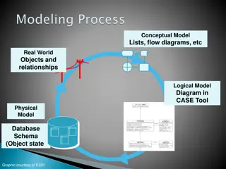
DATA BASE DESIGN Database Design The process of designing the general structure of the database: User requirements interaction with domain experts to carry out the specification of user requirements Conceptual design Translate the requirements into a conceptual schema Functional Requirements: user defines the kinds of operations that will be performed on data. Review of the schema to meet functional requirements Logical Design What attributes should we record in the database? What relation schemas should we have and how should the attributes be distributed among the various relation schemas? Deciding on the database schema. Database design requires that we find a good collection of relation schemas (no unnecessary redundancy, retrieve information easily) The most common approach is to use functionaldependencies Physical Design Deciding on the physical layout of the database
Data Base Design for Banking Enterprise Major characteristics The bank is organised into branches. Each branch is located in a particular city and is identified by a unique name. The bank monitors the assets of each branch. Bank customers are identified by their customer_id value. The bank stores each customer s name, and the street and the city where the customer lives. Customers may have accounts and can take out loans. A customer may be associated with a particular banker; who may act as a loan officer or personal banker for that customer. The bank offers two types of accounts: savings and checking accounts. Accounts can be held by more than one customer, and a customer can have more than one account. Each account is assigned a unique account number. The bank maintains a record of each account s balance and the most recent date on which the account was accessed by each customer holding the account. In addition each savings account has an interest rate, and overdrafts are recorded for each checking account.
Banking Enterprise The bank provides its customers with loans. A loan originates at a particular branch and can be held by one or more customers. A loan is identified by unique loan number. For each loan, the bank keeps track of loan amount and the loan payments. Although a loan-payment number does not uniquely identify a particular payment among those for all the bank s loans, a payment number does identify a particular payment for a specific loan. The date and the amount are recorded for each payment. Bank employees are identified by their employee_id values. The bank administration stores the name and telephone number of each employee, the names of the employee s dependents, and the employee_id number of the employee s manager. The bank also keeps track of the employee s start date and, thus, length of employment. To keep the example small, we do not keep track of deposits and withdrawals from savings and checking accounts, just as it keeps track of payments to loan accounts.