Understanding Magnetic Effects of Electric Current in Science Class
Explore the magnetic field and field lines, understand the magnetic effects of current-carrying conductors, learn about the right-hand thumb rule, and discover the magnetic field due to current through a circular loop in Chapter 13 of Magnetic Effects of Electric Current in Science Class at Sainik School Gopalganj.
Download Presentation

Please find below an Image/Link to download the presentation.
The content on the website is provided AS IS for your information and personal use only. It may not be sold, licensed, or shared on other websites without obtaining consent from the author. Download presentation by click this link. If you encounter any issues during the download, it is possible that the publisher has removed the file from their server.
E N D
Presentation Transcript
CHAPTER - 13 MAGNETIC EFFECTS OF ELECTRIC CURRENT Class Subject Name of Teacher School :- X :- Science :- Dr A K Choubey (TGT Sc.) :- SAINIK SCHOOLGOPALGANJ
1) Magnetic field and Field lines :- a) Magnetic field :- The region around a magnet where the force of attraction or repulsion can be detected is called magnetic field. Magnetic field around a magnet can be detected by using a magnetic compass.
b) Magnetic field lines :- Magnetic field lines are the paths around a magnet along which the north pole of a magnetic compass needle tends to move. The magnetic field lines around a magnet can be observed by sprinkling iron filings around a magnet. It can also be observed by moving a magnetic compass around a magnet. i) The magnetic field lines emerge at the north pole and merge at the south pole. ii) The magnetic field lines are closer at the poles. iii) The magnetic field lines do not intersect each other.
2) Magnetic field due to a current carrying conductor :- If a magnetic compass is placed near a conductor carrying current (wire), the needle is deflected. This shows that a conductor carrying current has a magnetic field around it. If the direction of the current is from north to south, the deflection of the magnetic needle is towards the east. If the direction of the current is from south to north, the deflection of the needle is towards the west. The magnetic field around a current carrying straight conductor is in concentric circles. It can be observed by passing a current carrying straight conductor through a cardboard and sprinkling iron filings on it. N N E W S S
Right hand thumb rule :- The direction of the magnetic field around a conductor is given by the Right Hand Thumb Rule. It states that If a current carrying conductor is held in the right hand such that the thumb points in the direction of current, then the fingers wrapped around the conductor shows the direction of the magnetic field .
3) Magnetic field due to a current through a circular loop :- When current is passed through a circular conductor (loop) the magnetic field produced is in the form of concentric circles around the conductor. Towards the centre the arcs of the circles become larger and appears as straight line.
4) Magnetic field due to current in a solenoid :- A solenoid is a circular coil of wire in the shape of a cylinder. When current flows through a solenoid, it behaves like a bar magnet. The ends of the solenoid behaves like the North and South poles of a magnet. The magnetic field produced by a solenoid is similar to the magnetic field produced by a bar magnet. The strength of the magnetic field depends upon the strength of the current and the number of turns of the coil.
5) Electromagnet :- A strong magnetic field inside a solenoid can be used to magnetise a piece of magnetic material like a soft iron when placed inside the coil. Such a magnet is called an electromagnet. If electric current is passed through a wire wound around a piece of soft iron, it behaves like a magnet. Such a magnet is called an electromagnet. ( )
6) Force on a conductor carrying current in a magnetic field :- A.M.Ampere suggested that if a current carrying conductor produces a magnetic field and exerts a force on a magnet, then a magnet should also exerts a force on a current carrying conductor. Eg :- If an aluminium rod is suspended horizontally by a wire between the poles of a horse shoe magnet and current is passed through the wire, then the aluminium rod is displaced. If the direction of current is reversed, the direction of displacement is also reversed. The force exerted is maximum if the conductor is perpendicular to the magnetic field.
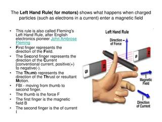
Flemings Left Hand Rule :- The direction of force (motion) of a current carrying conductor in a magnetic field is given by Fleming s Left Hand Rule. It states that If we hold the thumb, fore finger and middle finger of the left hand perpendicular to each other such that the fore finger points in the direction of magnetic field, the middle finger points in the direction of current, then the thumb shows the direction of force (motion) of the conductor .
7) Electromagnetic induction:- (Michael Faraday) The motion of a magnet with respect to a coil or a change in the magnetic field induce a potential difference in the coil and produces induced current. This is called electromagnetic induction. i) Motion of a magnet with respect to a coil produces induced current :- If a magnet is moved towards or away from a coil of wire connected to a galvanometer, the galvanometer needle shows a deflection. This shows that current is induced in the coil due to the motion of the magnet.
ii) Change in magnetic field produces induced current :- Take two coils of wires wound around a cylindrical paper roll. Connect one coil to a battery and the other coil to a galvanometer. If current is passed through the first coil, the galvanometer needle shows a deflection in the second coil. If the current is disconnected, the needle moves in the opposite direction. This shows that current is induced due to change in magnetic field. Coil -1 Coil - 2 ( ) battery key galvanometer
Flemings Right Hand Rule :- The direction of induced current is given by Fleming s Right Hand Rule. It states that If the thumb, fore finger and middle finger of the right hand is held perpendicular to each other such that the thumb points in the direction of motion of the conductor, the fore finger points in the direction of the magnetic field, then the middle finger shows the direction of induced current .
8) Direct and Alternating current :- a) Direct current (DC) :- A current that always flows in one direction only is called direct current. The current we get from a battery is a direct current. b) Alternating current (AC) :- A current that reverses its direction periodically is called alternating current. Most power stations in our country produce alternating current. AC changes direction every 1/100 second and its frequency is 50 Hertz (Hz). One advantage of AC over DC is that it can be transmitted over long distances without much loss of energy. Direct current Alternating current Current Current 0.01s 0.02s Time (s) Time
9) Domestic electric circuit :- Electric ity Meter Pole fuse Earth wire Distrbution box with main switch and fuses Electric power to homes is supplied through the mains. It has two wires. One is a live wire (positve wire) with red insulation and the other is a neutral wire (negative wire) with black insulation. The potential difference between the two wires is 220V. The earth wire with green insulation is connected to a metal plate kept in the ground. Two separate circuits are used. One is of 15A for appliances with high power rating like gysers, air conditioners etc. The other is of 5A for fans, bulbs etc. The different appliances are connected in parallel so that every appliance gets equal voltage and even if one is switched off the others are not affected. The appliances having metallic body like electric iron, refrigerators etc., their metallic body is connected to the earth wire so that if there is leakage of current, it passes to the earth and prevents electric shock.
10 a) Electric fuse :- Electric fuse is a safety device used in electric circuits to protect the circuit and appliances from damage due to overloading and short circuit. It is a wire having high resistance and low melting point. If excess current flows through the circuit, the fuse wire melts and breaks the circuit. Fuse wire is made of a metal or an alloy of metals like lead, tin, aluminium and copper. Fuse wire is connected in series with the live wire. b) Overloading :- Overloading is caused due to increase in voltage, or if the live wire and neutral wire comes in contact or if too many appliances are connected to a single socket. It results in overheating of the wires and can cause damage to the circuit and appliances. c) Short circuit :- Short circuit is caused when the live wire and neutral wire comes in contact and the current suddenly increases in the circuit. It causes spark, fire and damage to the circuit and appliances.
