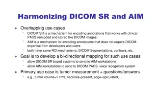
Overview of DICOM WG21 Multi-Energy Imaging Supplement
The DICOM WG21 Multi-Energy Imaging Supplement aims to address the challenges and opportunities in multi-energy imaging technologies, providing a comprehensive overview of imaging techniques, use cases, objectives, and potential clinical applications. The supplement discusses the definition of multi-energy imaging, examples of multi-energy CT, physics background, clinical use cases, objectives, and new aspects of multi-energy technologies. It emphasizes the importance of standardization for different vendors' technologies to achieve consistent and accurate diagnostic images.

Download Presentation

Please find below an Image/Link to download the presentation.
The content on the website is provided AS IS for your information and personal use only. It may not be sold, licensed, or shared on other websites without obtaining consent from the author. Download presentation by click this link. If you encounter any issues during the download, it is possible that the publisher has removed the file from their server.
E N D
Presentation Transcript
DICOM WG21 MULTI-ENERGY IMAGING SUPPLEMENT OVERVIEW 16-June-2015
Agenda Definitions, Use Cases, Objectives Aspects of Multi-Energy (ME) technologies New types of ME images Proposed Approach Risk and Concerns
ME-Definition Imaging techniques, including scanning, reconstruction, processing, when the scanner utilizes multiple energies from the X-Ray beam spectrum, as opposed to the conventional CT imaging, when a single (accumulated) X- Ray spectrum is used. The existing CT and Enhanced CT (eCT) IODs do not adequately describe the new CT multi-energy imaging. Although different vendors apply different scanning and detection techniques to achieve multi-energy images, there is large commonality in the generated diagnostic images.
Clinical Use Cases The primary potential applications this supplement intends to focus on include: Allowing better differentiation of materials that look similar on conventional CT images, e.g., to differentiate Iodine and Calcium in vascular structures Eliminating acquisitions such as non-contrast acquisition, when the virtual/artificial non-contrast image is generated from the contrast image
Objectives When defining this supplement, the following objectives / goals have been considered: 1. Making multi-energy information (acquisition, reconstruction and processing attributes) available to rendering or processing applications 2. Facilitating fast and easy adoption of this supplement across the imaging community, both modalities and PACS/Displays. 3. Eliminating (or at least minimizing) the risk of mis- interpretation when the ME images are displayed by a non-compliant display, including incorrect measurements
New aspects of ME technologies Different vendors apply different technologies for: Scanning Detection Reconstruction Processing Material decomposition This results in a variety of image types calling for standardization of parameters and definitions
Multi-Energy Imaging 4 categories Virtual Mono- chromatic Image (VMI) Material Quantification (Decomposition) Material Classification (Labeling) Material Visualization (Color) many flavors Material- Specific Image Effective AN (Z) Image Discrete Labeling Image Color Overlay Image Gout crystals on top of CT image Iodine Map; Bone Density Material- Subtracted Image Electron Density Image Proportiona l Map Image Color Blending Image Virt. Non-C; Virt. Non-Ca Material- Modified Image Probability Map Image Color Map Image Highlighted; Partially- Suppressed Color Eff. AN
Proposed approach For VMI and Quantification we reuse basic and enhanced CT IOD s for ME images For Classification we consider CT IOD, Segmentation IOD or Parametric Maps IOD For Visualization we consider reusing SC, Presentation States, Blending and may be Parametric map or adding RGB palette information to CT IOD Include the new attributes (add macros) in the existing IOD s Add new definitions to the existing standard (like Image Type, defined terms) Adapt some descriptions to multi-energy related cases Close to current implementations. Better chance to be widely/fast adopted
Virtual Mono-chromatic Image (VMI) Essentially analogous to a CT image that would be generated by a monochromatic (of a specific keV value) X-Ray beam 40 keV 167 keV
Material-Specific Image Iodine Map Image presenting a physical scale of specific material. Pixel values can be in HU or in equivalent material concentration (e.g., mg/ml).
Material-Subtracted Image Virtual Non-Contrast Image Image with one or more materials subtracted. Pixel values may have been corrected for displacement of one material by another material.
Material-Modified Image Bone Marrow Image Image where pixel values have been modified to highlight a certain target material (either by partially suppressing the background or by enhancing the target material), or to partially suppress the target material. Unlike Material-Specific and Material- Subtracted images (that can allow accurate measurements), the Material-Modified image is primary used for better visualization of the target materials
Electron Density Image An image where each pixel represents a number of electrons per unit volume. Widely used in radiotherapy.
Effective AN (Z) Image An image where each pixel represents Effective Atomic Number (aka Effective Z ) of that pixel.
Probability Map Image Gout Material Map An image where pixels describe the probability that this pixel is classified as one or more of the multiple defined materials
Material Visualization (Color) Users are asking to visualize ME-content in certain ways: color maps, color overlays, blending, etc.
How we intend to extend C.8.2.1 CT Image Module CT Additional X-Ray Source Sequence (0018,9360) (modified) Table X-1 Optional CT Multi-Energy Macro Attributes" (added) CT Multi Energy Acquisition Sequence (1C) >Table X-2 CT Multi-Energy Acquisition Macro Attributes CT Multi Energy Material Decomposition Sequence (1C) >Table X-3 CT Multi-Energy Material Decomposition Macro Attributes CT Multi Energy Image Sequence (1C) >Table X-4 CT Multi-Energy Image Macro Attributes C.8.15.3.9 CT X-Ray Details Macro (for Enhanced CT IOD only) CT X-Ray Details Sequence
Risk and Concerns Enhancements can be mis-interpreted in keV image need for correct display label including keV image type and keV value 50keV (virtual monochomatic) 100 kV (conventional)
Risk and Concerns High keV (>150) images can be mis-interpreted that no contrast was applied (missing contrast information) Potential risk for VNC images (e.g. changing size of small structures) currently not broadly validated that VNC is truly equivalent to TrueNonContrast Quantitative measurements are different in non-contrast vs. contrast use case (e.g. renal mass and renal cyst) Missing labeling can cause confusion which can slow down the workflow delay the diagnosis
Questions To guarantee that the created ME images contain the necessary information, a number of new attributes will be defined. These attributes will be added to the ME images, either as an extension to the existing IODs, or as part of new, ME-specific, IODs. However, we cannot mandate using any new specific attribute for existing IOD. Is there any workaround: Can we say that specific attribute is Type 1 if the system supports ME imaging? Yes only for new attributes; What about standard attributes, like Image Type? Ok to extend with new values and make them mandatory if the image is ME? Can we say that specific attribute is Type 1C if the units for pixels are not in HU? Not for existing attributes; ok for new Shall we rather define an optional SQ with mandatory ME attributes? Image Type of VMI Images. It is defined use ORIGINAL unless there is a specific case requiring it to be DERIVED. WG6 recommends leaving it to the vendor to decide if the image is ORIGINAL or DERIVED.
Questions To add Real-World Value Mapping to CT IOD to accurately describe the non-HU values. There are several concerns with this approach: RWVM is not specified today for CT images or widely implemented in the field (is this correct?). As a result, the units can be misinterpreted by the display application Rescale Slope and Rescale Intercept are Type-1 for CT image (if it is ORIGINAL); there is potential conflict between rescale attributes and RWVM. If we define image type as DERIVED, we avoid Type-1 requirement for Rescale Slope/Intercept, so they can be omitted. As a consequence, Rescale attributes shall be used if possible; for specific cases (to be identified) RWVM may be considered.
Questions To describe the need and recommendations for good labeling in the informative section (e.g., to display keV value for VMI images; to display material + concentration for measurements, etc.). DICOM alone cannot enforce PACS/Workstation to present specific attributes therefore there is little chance new important attributes we introduce here will be presented to the users. Should we work with IHE? Can we orchestrate the object in such a way that na ve display will either present the image adequately or fail to present anything? For instance, we can put rescale attributes to zero for non-HU ME images
Virtual Mono-chromatic Image (VMI) Renal Mass use case Contrast VMI Images 12 HU Non-Contrast Image - = 43 HU (160 keV) 206 HU 31 HU ( 120kV) 307 HU (50 keV)
DETAILS OF IMPLEMENTATION
ME Acquisition Techniques X-Ray Sources SINGLE_SOURCE MULTI_SOURCE KV Switching NONE, FAST, SLOW Multi-Energy Acquisition SINGLE_SCAN MULTI_SCAN Multi-Energy Detection CONVENTIONAL MULTILAYER PHOTON_COUNTING Technique-Specific Parameters: What do we want to record for Dual-Layer and PhC?
ME Material Decomposition Decomposition Method SINOGRAM_BASED IMAGE_BASED Decomposition Base Materials (sequence) Decomposition Description Vendor-specific label/description Material Attenuation Curves (opt) Decomposition Parameters e.g., dual-energy ratio
Pixel Value Units Method 1: using Rescale Rescale Slope Rescale Intercept Rescale Type Measurement Units as standard Coded Values e.g., UCUM: "mg/cm^3 Method 2 using Real World Value Mapping Sequence First/Last Values Mapped Value Slope/Intercept LUT (optional) Measurement Units (Coded Value)
Material Classification (Labeling) Proportional/Density Map: Discrete Labeling (most-probable material): ABCD 2 1.5 0: Unknown 1: Material A % or mg/ml 2: Material B 3: Material C Probability/Confidence Map: 0.2
Spectral Imaging Challenges Monochromatic Images Capture keV value How to differentiate from legacy CT? Incl. query, display annotations Material Density Images Non-HU values: how to avoid confusion? Several alternatives for solution Segmentation IOD Real-World Mapping PTE-like new IOD Rely on specific Rescale Intercept/Slope/Type Effective Atomic Number Images Similar challenges as for Material Density Using Color mapping prohibits measurements and analysis
Open Issues (some) Assess risks ME images been misinterpreted as the conventional ones on a PACS/Workstation AI: work through Mark Armstrong (ACR) to get radiologist to enumerate the risks How shall we model KV Switching? (including duration and gaps, proportion of High/Low KV) Alternative 1: Describe as two different sources Alternative 2: Single dynamic source KV-Switching specific parameters How shall we model Photon Counting detector? Shall we better describe the full Data Path ? Too complicated and vendor-specific? Each vendor to provide a list of potential public attributes specific for the each ME Acquisition/Recon techniques


")


 Image")

")


")

")