Analysis of Triple Beat Distortion in 3GPP TSG-RAN-WG4 Meeting #99-e
Analysis conducted during the electronic meeting of 3GPP TSG-RAN-WG4 focuses on the detection and impact of triple beat distortion in intra-band UL carrier aggregation and FDD UL configurations. The study delves into the mechanisms, causes, and effects of triple beat distortion on radio frequency signals, emphasizing the need for appropriate power back-off to meet emission and power class requirements in mobile communication systems.

Download Presentation

Please find below an Image/Link to download the presentation.
The content on the website is provided AS IS for your information and personal use only. It may not be sold, licensed, or shared on other websites without obtaining consent from the author. Download presentation by click this link. If you encounter any issues during the download, it is possible that the publisher has removed the file from their server.
E N D
Presentation Transcript
3GPP TSG-RAN WG4 Meeting #99-e Electronic meeting, 19 27 May 2021 R4-2107803 WF on MSD due to triple beat of intra-band UL CA UL + FDD UL configurations Qualcomm Inc., [ ],
Background 3A_n7B 28A_n7B 1A_n7B 1C_n3A 2C_n41A 2C_n71A 2A_n77(2A) 3A_n41C 3C_n1A 3C_n5A 3C_n7A 3C_n28A 3C_n41A 3A_n77(2A) 3A_n78(2A) 3C_n77A 3C_n78A 3C_n79A 7C_n1A 7C_n3A 7C_n5A 7C_n28A 7C_n78A 8A_n79C 25A_n41C 30_n77(2A) 39C_n41A 40C_n78A 41C_n3A 41C_n77A 41C_n78A 41C_n79A 42C_n28A 42C_n3A 66_n77(2A) Band combinations with 3 ULCCs were analyzed in [1] 3 active UL CCs create triple beat distortion and can lead to RX de-sensitization. Suspect band combinations from [1][2] that were detected to create triple beat distortion are highlighted and shown in table on the right ->
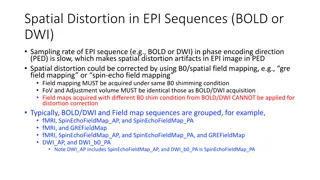
Background - detection The detection mechanism for the 1storder triple beat is shown below from [2] Duplex Offset is the duplex offset of the victim FDD band ULCAMBWis the non-contiguous 2 tone allocation spacing TXMBWand RXBW is the FDD victim band TX transmission measured BW and the RX DL channel BW respectively Band Y UL Band X_DL Band X_UL 1storder TripleBeat 2ndorder TripleBeat TripleBeat 3rdorder TripleBeat ULCAMBW ULCAMBW ULCAMBW ULCAMBW ULCAMBW Duplex
Background - analysis Triple beat distortion occurs at RX and TX and is a 3rdorder non-linearity that is mainly (TX22TX1) and is more prominent for non-contiguous RB allocations. For TX Both forward and reverse triple beat products can occur at the transmitter It was shown that the triple beat distortion at the ULCA transmitter path is dominant for TX due to 2:1 variation with ULCA output power PCB isolation from FDD band PA to ULCA band PA will affect forward TX distortion ULCA Filter rejection and antenna isolation will affect the reverse TX distortion For RX RX path filter rejection for both TX bands and the 3rdorder non-linearity specification determines the RX triple beat distortion Power Back-off For ULCA band, the power is backed off to meet the general emission requirements or CA_NS_04 requirement. this can be a function of tone spacing. For FDD band, the power is backed off to meet the NS_01 requirement Backed off power must meet the power class requirement Worst case triple beat will occur with equal power on the 3ULCCs if both power class and emission requirements are met.
WF: Example Analysis PC3 capable bands Tentatively agree on the following MSD values for the following band combinations for power class 3. Further verify power back off to meet power class and emission requirements ie. DC_3A_n77(2A) Back-off can be applied per carrier as indicated or per band DC_3A_n41C DC_25A_n41C DC_8A_n79C DC_28A_n7B DC_3C_n5 DC_7C_n5 DC_3A_n77(2A) 3A -4.78 n41C -4.78 25A -1 n41C -11.5 8A -4.78 n79C -4.78 28A -2 n7B -8.5 3C -8.5 n5 -2 7C -8.5 n5 -2 3A -1 n77(2A) -15 Back-off per Carrier, dB PA output Data, dBm Reverse TB-ULCA PA Forward TB-ULCA PA Reverse TB-FDD PA Forward TB-FDD PA -72.3 -78.3 -119.3 -123.3 -82.0 -84.7 -108.0 -142.5 -102.3 -100.3 -139.3 -143.3 -99.0 -102.6 -123.0 -145.8 -87.0 -102.6 -111.0 -133.8 -99.0 -71.6 -123.0 -145.8 -102.0 -78.7 -116.0 -160.5 LNA referred input, dBm Reverse TB-ULCA Forward TB-ULCA Reverse TB-FDD Forward TB-FDD PLNA TB _FDD RX DLNA TB_FDD RX IMD15 PLNA -112.3 -118.3 -174.3 -178.3 -87.7 DLNA -112.3 -118.3 -174.3 -178.3 PLNA -122.0 -124.7 -163.0 -197.5 -95.8 DLNA -122.0 -124.7 -163.0 -197.5 PLNA -152.3 -150.3 -194.3 -198.3 -110.3 DLNA -152.3 -150.3 -194.3 -198.3 PLNA -149.0 -152.6 -178.0 -200.8 -105.0 DLNA -149.0 -152.6 -178.0 -200.8 PLNA -137.0 -152.6 -166.0 -188.8 -96.4 DLNA -137.0 -152.6 -166.0 -188.8 PLNA -149.0 -121.6 -178.0 -200.8 -105.0 DLNA -149.0 -121.6 -178.0 -200.8 PLNA -147.0 -123.7 -166.0 -210.5 -118.0 DLNA -147.0 -123.7 -166.0 -210.5 -87.7 -99.8 -95.8 -106.5 -110.3 -105.0 -96.4 -105.0 -123.0 -99.8 -106.5 Antenna referred, dBm TB_Emission_dBm TX_IM2 Tx_noise TX_total Themal Composite PRX -83.4 -119.5 -104.2 -83.4 -96.0 -83.2 DRX -83.4 -119.5 -104.2 -83.4 -96.0 -83.2 PRX -91.4 -112.0 -99.3 -90.7 -96.0 -89.6 DRX -91.4 -112.0 -99.3 -90.7 -96.0 -89.6 PRX -106.3 -119.5 -104.1 -102.0 -96.0 -95.0 DRX -106.3 -119.5 -104.1 -102.0 -96.0 -95.0 PRX -101.0 -114.0 -100.7 -97.7 -91.0 -90.2 DRX -101.0 -114.0 -100.7 -97.7 -91.0 -90.2 PRX -95.4 -114.0 -98.5 -93.6 -91.0 -89.1 DRX -95.4 -114.0 -98.5 -93.6 -91.0 -89.1 PRX -103.9 -114.0 -98.5 -97.3 -91.0 -90.1 DRX -103.9 -114.0 -98.5 -97.3 -91.0 -90.1 PRX -107.5 -112.0 -100.5 -99.4 -96.0 -94.4 DRX -108.3 -112.0 -100.5 -99.5 -96.0 -94.4 MRC REFSENS -84.3 -91.1 -98.2 -93.5 -91.8 -93.3 -97.3 3GPP REFSENS MSD -97.0 -96.5 [5.4] -97.0 [0.0] -93.7 [0.2] -93.0 [1.2] -93.0 [0.0] -97.0 [0.0] [12.7]
WF: Framework for specification Mainly consider the 1storder triple beat (TX22TX1) of 3rdorder non-linearity -> this is shown in the table as triple beat order 1 Further check the 2ndorder triple beat (TX24TX1) of 5thorder non-linearity -> this would be shown in the table as triple beat order 2. This may come into play for higher TX power for power class 2 capable bands Neglect the 3rdorder triple beat (TX26TX1) of 7thorder non-linearity Verify MSD test points including RB positions and consider following framework for specification. NR or E-UTRA Band / Channel bandwidth / NRB/ MSD UL Fc (MHz) BW (MHz) EN-DC Configuratio n EUTRA or NR band UL/DL UL LCRB DL Fc (MHz) MSD (dB) Duplex mode Triple beat order 1 N/A 3 1782.5 2545 2595 5 25 1877.5 2545 2595 [12.7] N/A FDD TDD n41C 50 50 1 (RBstart=0) 1 (RBstart=250) 25 1 (RBstart=0) 1 (RBstart=250) 25 1 (RBstart=0) 1 (RBstart=250) DC_3A-n41C 25 1912.5 2545 2595 5 1992.5 2545 2595 [5.4] N/A FDD TDD 1 DC_25A- n41C n41C 50 50 N/A 8 912.5 4545 4595 5 957.5 4545 4595 [0] N/A FDD TDD 1 n79C 50 50 N/A DC_8A-n79C
References: [1] R4-2107627 Triple beat and 3ULCC MSD, Qualcomm Incorporated, R4#99-e [2] R4-2111016 MSD Due to NR Intra-band ULCA IMD within Inter-band Combinations, Apple, R4#99-e [3] R4-2105335 Way forward on analysis and framework of triple beat issue of 3CC UL with contiguous intra band UL CA , Qualcomm Inc., R4#98bis-e [4]