New Holland TC5.90 Hillside FPT NEF Tier 4B Combine Harvesters Service Repair Manual
To get the complete manual, please open the home page website.nnhttps://www.aservicemanualpdf.com/
Uploaded on | 1 Views
Download Presentation
Please find below an Image/Link to download the presentation.
The content on the website is provided AS IS for your information and personal use only. It may not be sold, licensed, or shared on other websites without obtaining consent from the author. Download presentation by click this link. If you encounter any issues during the download, it is possible that the publisher has removed the file from their server.
Presentation Transcript
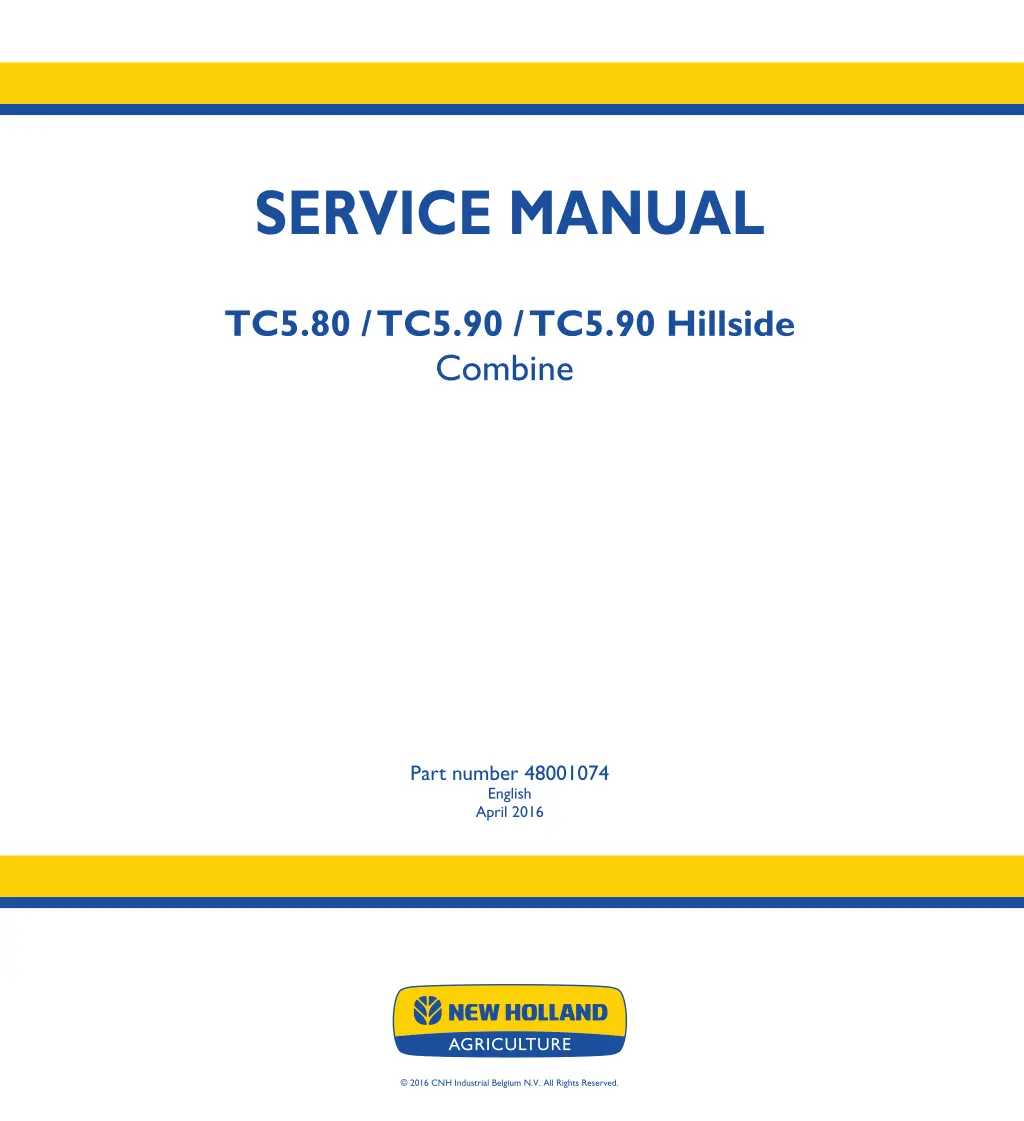
SERVICE MANUAL SERVICE MANUAL TC5.80 / TC5.90 / TC5.90 Hillside Combine TC5.80 TC5.90 TC5.90 Hillside Combine 1/3 Part number 48001074 English April 2016 Part number 48001074 2016 CNH Industrial Belgium N.V. All Rights Reserved.
SERVICE MANUAL TC5.80 FPT NEF TIER 4B TC5.90 FPT NEF TIER 4B TC5.90 Hillside FPT NEF TIER 4B 48001074 29/04/2016 EN
Link Product / Engine Product Market Product Europe Europe Engine TC5.80 FPT NEF TIER 4B TC5.90 FPT NEF TIER 4B TC5.90 Hillside FPT NEF TIER 4B Europe F4HFE6137*B003 F4HFE613D*B006 F4HFE613D*B006 48001074 29/04/2016
https://www.aservicemanualpdf.com/ My Dear Friend! Thank you very much for visiting. Full manual if required, please enter the following URL into your browser. https://www.aservicemanualpdf.com/
Contents INTRODUCTION Engine....................................................................................... 10 [10.450] Engine air compressor ............................................................. 10.1 [10.500] Selective Catalytic Reduction (SCR) exhaust treatment........................... 10.2 Transmission.............................................................................. 21 [21.114] Mechanical transmission ........................................................... 21.1 [21.130] Mechanical transmission external controls......................................... 21.2 [21.145] Gearbox internal components...................................................... 21.3 [21.182] Differential.......................................................................... 21.4 Front axle system ....................................................................... 25 [25.310] Final drives......................................................................... 25.1 Rear axle system........................................................................ 27 [27.100] Powered rear axle.................................................................. 27.1 [27.550] Non-powered rear axle............................................................. 27.2 Hydrostatic drive......................................................................... 29 [29.100] Transmission and steering hydrostatic control..................................... 29.1 [29.204] Reservoir, cooler, and lines ........................................................ 29.2 [29.218] Pump and motor components...................................................... 29.3 [29.202] Hydrostatic transmission ........................................................... 29.4 [29.300] Rear hydrostatic transmission...................................................... 29.5 Brakes and controls .................................................................... 33 [33.202] Hydraulic service brakes ........................................................... 33.1 [33.110] Parking brake or parking lock ...................................................... 33.2 Hydraulic systems....................................................................... 35 [35.000] Hydraulic systems.................................................................. 35.1 [35.300] Reservoir, cooler, and filters........................................................ 35.2 48001074 29/04/2016
[35.106] Variable displacement pump ....................................................... 35.3 [35.359] Main control valve.................................................................. 35.4 [35.204] Remote control valves ............................................................. 35.5 [35.610] Machine leveling control system ................................................... 35.6 [35.630] Machine lateral leveling system.................................................... 35.7 [35.640] Machine longitudinal leveling system .............................................. 35.8 [35.602] Header or attachment leveling system............................................. 35.9 [35.518] Reel control system .............................................................. 35.10 Steering..................................................................................... 41 [41.200] Hydraulic control components...................................................... 41.1 [41.101] Steering control .................................................................... 41.2 [41.206] Pump............................................................................... 41.3 [41.216] Cylinders ........................................................................... 41.4 Cab climate control..................................................................... 50 [50.200] Air conditioning..................................................................... 50.1 Electrical systems....................................................................... 55 [55.000] Electrical system ................................................................... 55.1 [55.100] Harnesses and connectors......................................................... 55.2 [55.988] Selective Catalytic Reduction (SCR) electrical system ............................ 55.3 [55.051] Cab Heating, Ventilation, and Air-Conditioning (HVAC) controls................... 55.4 [55.050] Heating, Ventilation, and Air-Conditioning (HVAC) control system................. 55.5 [55.834] Sieve electric control ............................................................... 55.6 [55.426] Harvest material flow control system............................................... 55.7 [55.618] Reverser electric control ........................................................... 55.8 [55.DTC] FAULT CODES.................................................................... 55.9 Attachments/Headers.................................................................. 58 [58.101] Attachment/Header reel............................................................ 58.1 [58.900] Belt feeding ........................................................................ 58.2 48001074 29/04/2016
Product feeding.......................................................................... 60 [60.101] Feed roll............................................................................ 60.1 [60.110] Feeder housing..................................................................... 60.2 [60.105] Floating roll, feed chain, and drive ................................................. 60.3 [60.150] Feeder drive system ............................................................... 60.4 [60.122] Length-of-cut gearbox.............................................................. 60.5 [60.165] Feeder reverse system............................................................. 60.6 Threshing .................................................................................. 66 [66.000] Threshing .......................................................................... 66.1 [66.330] Drum ............................................................................... 66.2 [66.321] Drum/Rotor variator with electrical control ......................................... 66.3 [66.105] Concave............................................................................ 66.4 [66.260] Threshing mechanism drive system ............................................... 66.5 Separation................................................................................. 72 [72.350] Beater .............................................................................. 72.1 [72.101] Straw walkers and shafts .......................................................... 72.2 Residue handling........................................................................ 73 [73.210] Straw chopper drive system........................................................ 73.1 [73.215] Straw chopper electro-magnetic clutch support.................................... 73.2 Cleaning.................................................................................... 74 [74.000] Cleaning............................................................................ 74.1 [74.101] Cleaning drive systems ............................................................ 74.2 [74.110] Grain pan........................................................................... 74.3 [74.114] Upper shaker shoe ................................................................. 74.4 [74.118] Lower shaker shoe ................................................................. 74.5 [74.130] Fan housing........................................................................ 74.6 [74.136] Fan drive system................................................................... 74.7 48001074 29/04/2016
[74.140] Tailings return system.............................................................. 74.8 Crop storage / Unloading............................................................. 80 [80.180] Grain tank unload .................................................................. 80.1 [80.101] Clean grain elevator................................................................ 80.2 Platform, cab, bodywork, and decals............................................. 90 [90.105] Machine shields and guards ....................................................... 90.1 [90.150] Cab................................................................................. 90.2 [90.156] Cab glazing ........................................................................ 90.3 48001074 29/04/2016
INTRODUCTION 48001074 29/04/2016 1
INTRODUCTION Foreword - Important notice regarding equipment servicing WE TC Harvest Suit Comfort Cab All repair and maintenance work listed in this manual must be carried out only by qualified dealership personnel, strictly complying with the instructions given, and using, whenever possible, the special tools. Anyone who performs repair and maintenance operations without complying with the procedures provided herein shall be responsible for any subsequent damages. The manufacturer and all the organizations of its distribution chain, including - without limitation - national, regional, or local dealers, reject any responsibility for damages caused by parts and/or components not approved by the manu- facturer, including those used for the servicing or repair of the product manufactured or marketed by the manufacturer. In any case, no warranty is given or attributed on the product manufactured or marketed by the manufacturer in case of damages caused by parts and/or components not approved by the manufacturer. The manufacturer reserves the right to make improvements in design and changes in specifications at any time without notice and without incurring any obligation to install them on units previously sold. Specifications, descriptions, and illustrative material herein are as accurate as known at time of publication but are subject to change without notice. In case of questions, refer to your NEW HOLLAND Sales and Service Networks. 48001074 29/04/2016 3
INTRODUCTION Safety rules WE TC Harvest Suit Comfort Cab LEGAL OBLIGATIONS This machine may be equipped with special guarding or other devices in compliance with local legislation. Some to these require active use by the operator. Therefor, check local legislations on the usage of this machine. ACCIDENT PREVENTION Most accidents or injuries that occur in workshops are the result of non compliance to simple and fundamental safety principles. For this reason, IN MOST CASES THESE ACCIDENTS CAN BE AVOIDED by applying the fundamental safety principles, acting with the necessary caution and care. Accidents may occur with all types of machine, regardless of how well the machine in question was designed and built. CAUTION Unexpected machine movement! 1. Disengage all drives. 2. Engage parking brake. 3. Lower all attachments to the ground, or raise and engage all safety locks. 4. Shut off engine. 5. Remove key from key switch. 6. Switch off battery key, if installed. 7. Wait for all machine movement to stop. Failure to comply could result in minor or moderate injury. C0038A SAFETY REQUIREMENTS FOR FLUID POWER SYSTEMS AND COMPONENTS - HY- DRAULICS (EUROPEAN STANDARD EN982) Flexible hose assemblies must not be constructed from hoses which have been previously used as part of a hose assembly. Do not weld hydraulic pipes: when flexible hoses or piping are damaged, replace them immediately. It is forbidden to modify a hydraulic accumulator by machining, welding or any other way. Before removing hydraulic accumulators for servicing, the liquid pressure in the accumulators must be reduced to zero. Pressure check on hydraulic accumulators must be carried out by a method recommended by the accumulator manufacturer. Take care not to exceed the maximum allowed pressure of the accumulator. After any check or adjustment, check for leakages or gas in the hoses or tubes. SAFETY RULES General guidelines Carefully follow specified repair and maintenance procedures. When appropriate, use P.P.E (Personal Protective Equipment) Do not wear rings, wristwatches, jewellery, unbuttoned or loose articles of clothing such as: ties, torn clothing, scarves, open jackets or shirts with open zips that may remain entangled in moving parts. It is advised to wear approved safety clothing, e.g.: non-slip footwear, gloves, safety goggles, helmets, etc. Do not carry out repair operations with someone sitting in the driver's seat, unless the person is a trained technician who is assisting with the operation in question. Do not operate the machine or use any of the implements from different positions, other than the driver's seat. 48001074 29/04/2016 4
INTRODUCTION Do not carry out operations on the machine with the engine running, unless specifically indicated. Bring all hydraulic cylinders to the home positions (down, retracted, etc.) before engine shut down. Stop the engine and check that the hydraulic circuits are pressure-free before removing caps, covers, valves, etc. All repair and maintenance operations must be carried out using extreme care and attention. Service steps and platforms used in the workshop or elsewhere should be built according to the applicable stan- dards and legislation. Disconnect the Power Take-Off (PTO) and label the controls to indicate that the machine is being serviced. Brakes are inoperative when manually released for repair or maintenance purposes. Use blocks or similar devices to secure the machine in these conditions. Only use specified towing points for towing the machine. Connect parts carefully. Make sure that all pins and/or locks are secured in position before applying traction. Never remain near the towing bars, cables or chains that are operating under load. When loading or unloading the machine from the trailer (or other means of transport), select a flat area capable of sustaining the trailer or truck wheels. Firmly secure the machine to the truck or trailer and lock the wheels in the position used by the carrier. Electric heaters, battery-chargers and similar equipment must only be powered by auxiliary power supplies with efficient ground insulation to avoid electrical shock hazards. Always use suitable hoisting or lifting devices when raising or moving heavy parts. Keep bystanders away. Never use gasoline, diesel oil or other inflammable liquids as cleaning agents. Use non-inflammable, non toxic commercially available solvents. Wear safety goggles with side guards when cleaning parts with compressed air. Never use open flames for lighting when working on the machine or checking for leaks. When carrying out checks with the engine running, request the assistance of an operator in the driver's seat. The operator must maintain visual contact with the service technician at all times. If operating outside the workshop, position the machine on a flat surface and lock in position. If working on a slope, lock the machine in position. Move to a flat area as soon as is safely possible. Maintenance and repair operations must be carried out in a clean and dry area. Clean up any water or oil spillage immediately. Do not create piles of oil or grease-soaked rags as they represent a serious fire hazard. Always store rags in a closed metal container. Before engaging the machine, make sure that there are no persons within the machine or implement range of action. Empty your pockets of all objects that may fall accidentally unobserved into the machine inner compartments. When metal parts are sticking out, use protective goggles or goggles with side guards, helmets, special footwear and gloves. When welding, use protective safety devices: tinted safety goggles, helmets, special overalls, gloves and footwear. All persons present in the area where welding is taking place must wear tinted goggles. NEVER LOOK DIRECTLY AT THE WELDING ARC WITHOUT SUITABLE EYE PROTECTION. 48001074 29/04/2016 5
SERVICE MANUAL Engine TC5.80 FPT NEF TIER 4B TC5.90 FPT NEF TIER 4B TC5.90 Hillside FPT NEF TIER 4B 48001074 29/04/2016 10
Engine - Engine air compressor Air compressor - Static description WE WE WE TC5.80 TC5.90 Hillside TC5.90 The air compressor (3) is a single cylinder, gear driven air compressor, which supplies air to a reservoir tank, enabling the operator to have a source of compressed air for cleaning purposes and tyre inflation. The compressor is mounted directly on the engine with the two nuts (10). Engine oil is supplied through an internal connection with the engine, using engine oil pressure to lubricate the com- pressor. The compressed air is delivered through tubing to a combination pressure relief control valve, and from there to the reservoir tank located on the straw hood of the combine. A quick disconnect fitting allows easy connection to the air supply for blow off nozzles as well as for tyre inflation equipment. 1 ZEIL06CS0085A0B 48001074 29/04/2016 10.1 [10.450] / 3
Engine - Engine air compressor Air compressor - Drawing WE WE WE TC5.80 TC5.90 Hillside TC5.90 1 ZEIL11CX0668G0B Port 0 2 8.1 8.2 9.1 9.2 Port Name Inlet Port Discharge Port Oil Supply Oil Drain Coolant Coolant Port Function Reference 1 2 4 5 6 7 Supplies Compressor with clean intake air Expels pressurized air for system Supplies compressor with lube oil from engine Allows lube oil to return to engine Receive coolant from engine Return coolant to engine 48001074 29/04/2016 10.1 [10.450] / 4
Engine - Engine air compressor Compressed air tank Relief valve - Drawing WE WE WE TC5.80 TC5.90 Hillside TC5.90 1 ZEIL11CX0667G0B Port 1 21 Port name Inlet Outlet Reference 1 2 Port function Pressurized air "in" from compressor Pressurized air "out" to reservoir tank and blow off line quick connect port Auxiliary port not used in this application Port used to connect tire inflation device Discharge exhaust for excess pressure in system 3 4 5 22 1-2 3 Auxiliary supply Tire inflation device Exhaust for compressor idling 48001074 29/04/2016 10.1 [10.450] / 5
Engine - Engine air compressor Compressed air tank Relief valve - Static description WE WE WE TC5.80 TC5.90 Hillside TC5.90 The pressure relief valve is developed to protect the system against pressures higher than 8 bar ( 116 psi). Port (1) is connected to the air compressor, port (21) is connected to the pressurized reservoir. When the pressure on port (21) reaches 8 bar ( 116 psi), the control valve (9d) will be activated which means that also control valve (9c) will be activated. The pressure from the compressor will now pass through port (3). If the pressure drops below 8 bar ( 116 psi) by activation a engaging valve, control valve (9d) will close. Valve (9c) will not close immediately but will remain in the open position until the pressure exerted on the control of valve (9c) will be reduced by 0.6 bar ( 8.7 psi). Then the air will pass through valve (9b). Schematic diagram 1 ZDA7672Z 48001074 29/04/2016 10.1 [10.450] / 6
Engine - Engine air compressor Air compressor - Remove WE WE WE TC5.80 TC5.90 Hillside TC5.90 1. Bleed the air from the system by opening the drain (2) at the bottom of the air reservoir. 1 ZEIL06TC00034A0 2. Loosen the retaining strap (1) and remove the air inlet pipe (2) from the air compressor (3). NOTE: Protect the air inlet and outlet ports from dirt ingress. 3. Loosen the connection (4) to remove the hose (5) from the air compressor (3). 2 ZEIL06CS0082A0B 4. Drain sufficient coolant from the engine cooling system to allow removal of the coolant lines. NOTE: Refer to the Operator s Manual of your machine. 5. Loosen the connection (6). 3 ZEIL06CS0083A0B 48001074 29/04/2016 10.1 [10.450] / 7
Engine - Engine air compressor 6. Loosen the connection (7). 7. Remove the four bolts (8) to remove the support (9). 4 ZEIL06CS0084A0B 8. Removethetwonuts(10)toremovetheaircompressor (3) from the engine. 5 ZEIL06CS0085A0B 48001074 29/04/2016 10.1 [10.450] / 8
Engine - Engine air compressor Air compressor - Install WE WE WE TC5.80 TC5.90 Hillside TC5.90 1. Install the air compressor (3) on the engine and tighten the two nuts (10). 1 ZEIL06CS0085A0B NOTE: Make sure that the O-ring (11) is positioned well. If necessary apply grease. 2 ZEIL06CS0086A0B 2. Install the support (9) with the four bolts (8). 3. Install the tube and tighten the connection (7). 3 ZEIL06CS0084A0B 48001074 29/04/2016 10.1 [10.450] / 9
Engine - Engine air compressor 4. Install the tube and tighten the connection (6). 4 ZEIL06CS0083A0B 5. Install the hose (5) on the air compressor (3) and tighten the connection (4). 6. Install the pipe (2) on the air compressor (3) and tighten the retaining strap (1). 5 ZEIL06CS0082A0B 7. Close the drain (2) at the bottom of the reservoir. 8. Add engine coolant to the cooling system, refer to the Operator s Manual for more details. 9. Starttheenginetochargethesystemwithair. Allowthe air system to build up pressure to the governor cutout. Stop the engine and use a soap and water solution at the connection points to check for air leaks. Make any necessary repairs. 6 ZEIL06TC00034A0 48001074 29/04/2016 10.1 [10.450] / 10
Engine - Selective Catalytic Reduction (SCR) exhaust treatment Selective Catalytic Reduction (SCR) exhaust treatment - Remove - Exhaust flap 1. Drain the coolant reservoir. See the operator s manual. 2. Loosen the screw (1) and open the clamp. 3. Loosen the screw (3) and open the clamp. 4. Remove the elbow (2) together with the flexible cou- pling from between the Diesel Oxidation Catalyst (DOC) and the exhaust flap. NOTE: Make sure you do not lose the gasket located be- tween the elbow and the DOC and the gasket located be- tween the flexible coupling and the exhaust valve. 1 ZEIL15TC00321AA 5. Undo the snap buttons of the heat resistant sleeve (5) to access and disconnect the connector (6). 6. Disconnect the water inlet (8) from the exhaust flap (4) (from water pump to exhaust flap). 7. Disconnect the water outlet (7) from the exhaust flap (4) (from exhaust flap to engine). 2 ZEIL15TC00322AA 8. Loosen the screw (9) and open the clamp. 9. Remove the hardware (11) (four in total), the support (10), and the exhaust flap (4). 3 ZEIL15TC00323AA 48001074 29/04/2016 10.2 [10.500] / 3
Engine - Selective Catalytic Reduction (SCR) exhaust treatment Selective Catalytic Reduction (SCR) exhaust treatment - Install - Exhaust flap 1. Install the exhaust flap (4) on the outlet manifold. Make sure the gasket between the turbo and the exhaust flap (4) is properly installed. Use the hardware (11) (four in total) and the support (10), do not tighten yet. 2. Orienttheclampasshown. Closetheclampandtorque the screw (9) between 5 - 7 N m (3.7 - 5.2 lb ft). 3. Torque the hardware (11) to 25 N m (18.4 lb ft). 1 ZEIL15TC00323AA 4. Connect the water outlet (7) to the exhaust flap (4) (from exhaust flap to engine). (14.8 lb ft). Torque to 20 N m 5. Connect the water inlet (8) to the exhaust flap (4) (from water pump to exhaust flap). Torque to 20 N m(14.8 lb ft). 6. Connect the connector (6). Close the snap buttons of the heat resistant sleeve (5) and make sure it protects the connector (6) and wire harness properly. 2 ZEIL15TC00322AA 7. Install the elbow (2) together with the flexible coupling between the Diesel Oxidation Catalyst (DOC) and the exhaust flap. Make sure the gasket between the elbow and the DOC, and the gasket between the flexible cou- pling and the exhaust flap are properly installed. 8. Orient the screw (1) of the clamp as shown. Torque the screw (1) between 6 - 8 N m (4.4 - 5.9 lb ft). 9. Orient the screw (3) of the clamp as shown. Torque the screw (3) between 6 - 8 N m (4.4 - 5.9 lb ft). 3 ZEIL15TC00321AA 10. Fill the coolant reservoir. See the operator s manual. 48001074 29/04/2016 10.2 [10.500] / 4
Engine - Selective Catalytic Reduction (SCR) exhaust treatment Selective Catalytic Reduction (SCR) muffler and catalyst - Remove 1. Behind the oil reservoir, cut the straps (1). 2. Disconnect the connector (2A). 1 ZEIL15TC00317AA 3. Remove the NH3 sensor (2). 4. Remove the temperature sensor (4). 5. Remove the NOx sensor (5). 6. Loosen the clamp (3). 7. Remove the hardware that mounts the clamp (6) to the Diesel Oxidation Catalyst (DOC). 2 ZEIL15TC00316AA 8. Remove the temperature sensor (10). 9. Loosen the clamp (7). 10. Remove the hardware (8) of the clamp. 11. Remove the air suction tube (9). 3 ZEIL15TC00318AA 12. Remove the hardware (11) and the plate (12). 13. Remove the hardware (14) and the heat shield (13). 4 ZEIL15TC00318AA 48001074 29/04/2016 10.2 [10.500] / 5
Engine - Selective Catalytic Reduction (SCR) exhaust treatment 14. Remove the hardware (16) and the heat shield (15). 5 ZEIL15TC00313AA 15. Remove the bolt (18) of both straps (17). 6 ZEIL15TC00319AA 16. Loosen the screw of the clamp (20) and open the clamp (20). 17. Loosen the screw of the clamp (21) and open the clamp (21). 18. Remove the tube (19). Make sure you do not lose the gasket between the DOC and the tube (19) and the gasket between the tube (19) and the muffler (22). 7 ZEIL15TC00320AA 19. Loosen the clamp (23) and remove the exhaust tube (24). 20. Remove the muffler (22). Use a suitable lifting device. 8 ZEIL16TC00062AA 48001074 29/04/2016 10.2 [10.500] / 6
Thank you very much for your reading. Please Click Here. Then Get COMPLETE MANUAL. NO WAITING NOTE: If there is no response to click on the link above, please download the PDF document first and then click on it.
Engine - Selective Catalytic Reduction (SCR) exhaust treatment Selective Catalytic Reduction (SCR) muffler and catalyst - Install 1. Install the muffler (22). Use a suitable lifting device. 2. Install the exhaust tube (24) and the clamp (23) on the muffler, torque between 40 - 50 N m (29.5 - 36.9 lb ft). 1 ZEIL16TC00062AA 3. Install the tube (19). Make sure the gasket between the Diesel Oxidation Catalyst (DOC) and the tube (19), and the gasket between the tube (19) and the muffler (22) are properly installed. 4. Close the clamp (21) and torque between 18 - 22 N m (13.3 - 16.2 lb ft). 5. Orient the clamp (20) with the screw on the underside and in a horizontal position. Close the clamp (20) and torque between 6 - 8 N m (4.4 - 16.2 lb ft). 2 ZEIL15TC00320AA 6. Tighten the bolt (18) of both straps (17). 3 ZEIL15TC00319AA 7. Install the heat shield (15). Use the hardware (16). 4 ZEIL15TC00313AA 48001074 29/04/2016 10.2 [10.500] / 7
Engine - Selective Catalytic Reduction (SCR) exhaust treatment 8. Install the heat shield (13). Use the hardware (14). 9. Install the plate (12). Use the hardware (11). 5 ZEIL15TC00318AA 10. Install the air suction tube (9). Use the hardware (8). 11. Install the hardware that mounts the clamp (6) to the DOC. See Figure 7. 12. Tighten the clamp (7). 13. Tighten the clamp (3). See Figure 7. 14. Install the temperature sensor (10). Torque between 40 - 50 N m (29.5 - 36.9 lb ft). 6 ZEIL15TC00318AA 15. Install the temperature sensor (4). Torque between 40 - 50 N m (29.5 - 36.9 lb ft). 16. Install the NOx sensor (5), apply WEICON HIGH-TECH ASSEMBLY PASTE on the threads. Torque between 40 - 60 N m (29.5 - 44.3 lb ft). 17. Install the NH3 sensor (2), apply LOCTITE X203 DRY FILM MOLY ANTI-SEIZE on the threads. Torque be- tween 40 - 60 N m (29.5 - 44.3 lb ft). 7 ZEIL15TC00316AA 18. Connect the connector (2A). 19. Tie up the cables of the sensors. Use the straps (1). NOTICE: Do not use straps on the protection tube of the NH3 sensor. This piece must have a minimum bend radius of 50 mm (2 in) at a 90 maximum bend angle. 8 ZEIL15TC00317AA 48001074 29/04/2016 10.2 [10.500] / 8
Engine - Selective Catalytic Reduction (SCR) exhaust treatment Diesel Exhaust Fluid (DEF)/AdBlue filters - Service instruction Main filter 1. On the supply module (1). Remove the filter cover (2), turn counter-clockwise. NOTE: Required tool : 27 mm wrench. 1 ZEIL15TC00307AA 2. Remove the equalizing element (3). 2 ZEIL15TC00308AA 3. Check the color of the filter (4) inside. 3 ZEIL15TC00309AA 4. Choose the correct side of the tool (5) that comes with the replacement filter. (B) side for black filter. (G) side for grey filter. 4 ZEIL15TC00310AA 48001074 29/04/2016 10.2 [10.500] / 9
Engine - Selective Catalytic Reduction (SCR) exhaust treatment 5. Insert the correct side of the tool (5) into the filter (4) until a click is noticed. 6. Pull out the filter (4) with the tool (5) by hand. If nec- essary insert a screwdriver in the slot of the tool (5) to help extract the filter (4). 5 ZEIL15TC00311AA 7. Clean functional surfaces indicated by the arrow with clean water only. NOTE: Protect the filter chamber from contamination and particles. 8. Lubricate the O-rings (6) with MOBIL VELOCITE NO. 6 OIL and insert the new filter (4) into the supply module (1). 6 ZEIL15TC00312AA 9. Insert the new equalizing element (3). 7 ZEIL15TC00308AA 10. On the supply module (1). Install the filter cover (2), clockwise. Torque to 15 - 25 N m (132.8 - 221 lb in). 8 ZEIL15TC00307AA 48001074 29/04/2016 10.2 [10.500] / 10
Engine - Selective Catalytic Reduction (SCR) exhaust treatment In-line filter 11. Remove the cover (2) from the housing (1). NOTE: Required tools: 24 mm and 27 mm wrench. 9 ZEIL16TC00023AA 12. Remove the spacer (3) from the housing (1). 13. Remove the filter (4) from the cover (2). 10 ZEIL16TC00003AA 14. Clean the housing (1), the spacer (3) and the cover (2) with clean water only. 15. Check the O-ring (5) and the O-ring (6) for damage, replace if necessary. 11 ZEIL16TC00003AZ 16. Install the new filter (4) on the cover (2). 17. Install the spacer (3) inside the housing (1). 12 ZEIL16TC00003AA 48001074 29/04/2016 10.2 [10.500] / 11
https://www.aservicemanualpdf.com/ My Dear Friend! Thank you very much for visiting. Full manual if required, please enter the following URL into your browser. https://www.aservicemanualpdf.com/

