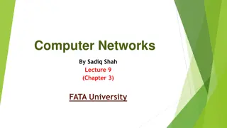
Understanding Impairments in Wireline Communication Channels
Wireline communication channels can experience various impairments such as linear time-invariant effects like attenuation and spreading, as well as linear time-varying effects like phase jitter, nonlinear effects, additive noise, and interference. These impairments can affect the quality of transmitted signals and pose challenges in maintaining signal integrity. It is important to address and mitigate these impairments to ensure reliable communication in wired systems.

Download Presentation

Please find below an Image/Link to download the presentation.
The content on the website is provided AS IS for your information and personal use only. It may not be sold, licensed, or shared on other websites without obtaining consent from the author. Download presentation by click this link. If you encounter any issues during the download, it is possible that the publisher has removed the file from their server.
E N D
Presentation Transcript
EE445S Real-Time Digital Signal Processing Lab Spring 2014 Channel Impairments Prof. Brian L. Evans Dept. of Electrical and Computer Engineering The University of Texas at Austin Lecture 12 http://courses.utexas.edu/
Outline Analog communication systems Channel impairments Hybrid communication systems Analog pulse amplitude modulation 12 - 2
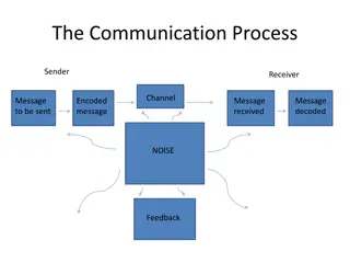
Communication Systems Communication System Structure Information sources Voice, music, images, video, and data (baseband signals) Transmitter Signal processing block lowpass filters message signal Carrier circuits block upconverts baseband signal and bandpass filters to enforce transmission band baseband baseband bandpass bandpass baseband baseband Signal Processing Carrier Circuits Transmission Medium Carrier Circuits Signal Processing ( t m m(t) ) s(t) r(t) TRANSMITTER CHANNEL RECEIVER 12 - 3
Review Communication Channel Transmission medium Wireline (twisted pair, coaxial, fiber optics) Wireless (indoor/air, outdoor/air, underwater, space) Propagating signals degrade over distance Repeaters can strengthen signal and reduce noise baseband baseband bandpass bandpass baseband baseband Signal Processing Carrier Circuits Transmission Medium Carrier Circuits Signal Processing ( t m m(t) ) s(t) r(t) TRANSMITTER CHANNEL RECEIVER 12 - 4
Wireline Channel Impairments Linear time-invariant effects Attenuation: dependent on channel frequency response Spreading: finite extent of each transmitted pulse increases ( ) y 0t ( ) 0t x input output b h+ b h Communication Channel t t x(t) y(t) -A Th -A ( ) 1t x ( ) 1t y (t ) h Model channel as LTI system with impulse response h(t) A A Th 1 t b t h h h+ b t Assume that Th < Tb Bit of 0 or 1 12 - 5
Wireline Channel Impairments Linear time-varying effects Phase jitter: sinusoid at same fixed frequency experiences different phase shifts when passing through channel Visualize phase jitter in periodic waveform by plotting it over one period, superimposing second period on the first, etc. Nonlinear effects Harmonics: due to quantization, voltage rectifiers, squaring devices, power amplifiers, etc. Additive noise: arises from many sources in transmitter, channel, and receiver (e.g. thermal noise) Additive interference: arises from other systems operating in transmission band (e.g. microwave oven in 2.4 GHz band) 12 - 6
Home Power Line Noise/Interference Power Spectral Density Estimate -75 -80 Power/frequency (dB/Hz) -85 -90 -95 -100 -105 -110 -115 -120 -125 0 10 20 30 40 50 60 70 80 90 Frequency (kHz) Measurement taken on a wall power plug in an apartment in Austin, Texas, on March 20, 2011 12 - 7
Home Power Line Noise/Interference Power Spectral Density Estimate -75 -80 Power/frequency (dB/Hz) -85 -90 -95 -100 -105 -110 -115 Spectrally-Shaped Background Noise -120 -125 0 10 20 30 40 50 60 70 80 90 Frequency (kHz) Measurement taken on a wall power plug in an apartment in Austin, Texas, on March 20, 2011 12 - 8
Home Power Line Noise/Interference Power Spectral Density Estimate -75 Narrowband Interference -80 Power/frequency (dB/Hz) -85 -90 -95 -100 -105 -110 -115 Spectrally-Shaped Background Noise -120 -125 0 10 20 30 40 50 60 70 80 90 Frequency (kHz) Measurement taken on a wall power plug in an apartment in Austin, Texas, on March 20, 2011 12 - 9
Home Power Line Noise/Interference Power Spectral Density Estimate Periodic and Asynchronous Interference -75 Narrowband Interference -80 Power/frequency (dB/Hz) -85 -90 -95 -100 -105 -110 -115 Spectrally-Shaped Background Noise -120 -125 0 10 20 30 40 50 60 70 80 90 Frequency (kHz) Measurement taken on a wall power plug in an apartment in Austin, Texas, on March 20, 2011 12 - 10
Wireless Channel Impairments Same as wireline channel impairments plus others Fading: multiplicative noise Talking on a mobile phone and reception fades in and out Represented as time-varying gain that follows a particular probability distribution Simplified channel model for fading, LTI effects and additive noise FIR 0 a + noise 12 - 11
Hybrid Communication Systems Mixed analog and digital signal processing in the transmitter and receiver Example: message signal is digital but broadcast over an analog channel (compressed speech in digital cell phones) Signal processing in the transmitter Error Correcting Codes Digital Signaling A/D D/A Converter Converter m(t) Signal processing in the receiver baseband signal A/D Equalizer Detection Decoder Waveform Generator D/A digital sequence digital sequence code 12 - 12
Optional Pulse Amplitude Modulation (PAM) Amplitude of periodic pulse train is varied with a sampled message signal m(t) Digital PAM: coded pulses of the sampled and quantized message signal are transmitted (lectures 13 and 14) Analog PAM: periodic pulse train with period Ts is the carrier (below) m(t) s(t) = p(t) m(t) p(t) t 12 - 13 T Ts T+Ts 2Ts
Optional Analog PAM Pulse amplitude varied with amplitude of sampled message Sample message every Ts Hold sample for T seconds (T < Ts) Bandwidth 1/T Transmitted signal ) ( m t s n = = ( ) ( ) T n h t T n s s sample hold h(t) is a rectangular pulse of duration T units , 0 t 1 for 0 t T / 1 = = = ( ) 2 for h t t T 0 otherwise s(t) m(0) m(t) h(t) 1 As , 0 T m(Ts) 1 T ( ) ( ) h t t t t T T Ts T+Ts 2Ts 12 - 14
Optional Analog PAM Transmitted signal = Equalization of sample and hold distortion added in transmitter H(f) causes amplitude distortion and delay of T/2 Equalize amplitude distortion by post-filtering with magnitude response 1 ) ( T f H = ( ) ( ) ( ) s t m T n h t T n s s n ( ) = = ( ) ( ) * ( ) m T n t T n h t s s n = = ( ) ( ) * ( ) m T n t T n h t s s n msampled(t) Fourier transform ) ( f S = ( ) ( ) M f H f 1 f sampled = = s = sinc sinc ( ) sin ( ) f T f T = ( ) ( ) f M f f k H f s k Negligible distortion (less than 0.5%) if T = j 2 T / 2 f ( ) ( T ) H f T f e 1 . 0 sT = T j f sinc ( T ) T f e 12 - 15
Optional Analog PAM Requires transmitted pulses to Not be significantly corrupted in amplitude Experience roughly uniform delay Useful in time-division multiplexing public switched telephone network T1 (E1) line time-division multiplexes 24 (32) voice channels Bit rate of 1.544 (2.048) Mbps for duty cycle < 10% Other analog pulse modulation methods Pulse-duration modulation (PDM), a.k.a. pulse width modulation (PWM) Pulse-position modulation (PPM): used in some optical pulse modulation systems. 12 - 16