JCB VM115 TIER II Roller Service Repair Manual Instant Download
Please open the website below to get the complete manualnn//

Download Presentation

Please find below an Image/Link to download the presentation.
The content on the website is provided AS IS for your information and personal use only. It may not be sold, licensed, or shared on other websites without obtaining consent from the author. Download presentation by click this link. If you encounter any issues during the download, it is possible that the publisher has removed the file from their server.
E N D
Presentation Transcript
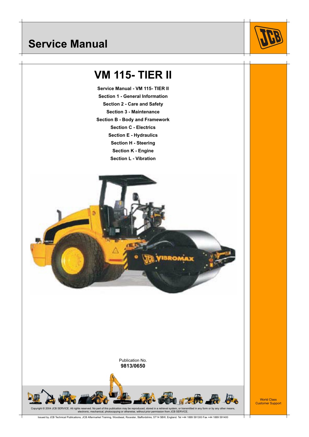
Service Manual VM 115- TIER II Service Manual - VM 115- TIER II Section 1 - General Information Section 2 - Care and Safety Section 3 - Maintenance Section B - Body and Framework Section C - Electrics Section E - Hydraulics Section H - Steering Section K - Engine Section L - Vibration Publication No. 9813/0650 World Class Customer Support Copyright 2004 JCB SERVICE. All rights reserved. No part of this publication may be reproduced, stored in a retrieval system, or transmitted in any form or by any other means, electronic, mechanical, photocopying or otherwise, without prior permission from JCB SERVICE. Issued by JCB Technical Publications, JCB Aftermarket Training, Woodseat, Rocester, Staffordshire, ST14 5BW, England. Tel +44 1889 591300 Fax +44 1889 591400
Section 1 General Information Service Manual - VM 115- TIER II Section 1 - General Information Section 2 - Care and Safety Section 3 - Maintenance Section B - Body and Framework Section C - Electrics Section E - Hydraulics Section H - Steering Section K - Engine Section L - Vibration Publication No. 9813/0650 World Class Customer Support Copyright 2004 JCB SERVICE. All rights reserved. No part of this publication may be reproduced, stored in a retrieval system, or transmitted in any form or by any other means, electronic, mechanical, photocopying or otherwise, without prior permission from JCB SERVICE. Issued by JCB Technical Publications, JCB Aftermarket Training, Woodseat, Rocester, Staffordshire, ST14 5BW, England. Tel +44 1889 591300 Fax +44 1889 591400
Section 1 - General Information Contents Introduction About This Manual ....................................................................................1 - 1 Machine Model and Serial Number .....................................................1 - 1 Using this Manual ................................................................................1 - 1 Cab/Canopy ........................................................................................1 - 1 Left Side, Right Side ............................................................................1 - 1 Cross References ................................................................................1 - 1 Machine Description .................................................................................1 - 2 The JCB Vibromax Vibratory Single Drum Roller ................................1 - 2 ............................................................................................................1 - 2 Component Locations .........................................................................1 - 3 Safety Labels ............................................................................................1 - 5 Introduction ..........................................................................................1 - 5 Safety Label Identification ...................................................................1 - 6 Identifying Your Machine ..........................................................................1 - 8 Machine Identification Plate ................................................................1 - 8 Component Identification Plates ..........................................................1 - 9 Machine Security ....................................................................................1 - 10 Construction Equipment Security And Registration Scheme (CESAR) .1 - 10 Page No. Service Consumables Sealing and Retaining Compounds ........................................................1 - 11 Service Tools Numerical List .........................................................................................1 - 13 Tool Detail Reference .............................................................................1 - 15 Section B - Body and Framework ......................................................1 - 15 Section C - Electrics ..........................................................................1 - 18 Section E - Hydraulics .......................................................................1 - 19 Torque Settings Zinc Plated Fasteners and Dacromet Fasteners ....................................1 - 24 Introduction ........................................................................................1 - 24 Bolts and Screws ...............................................................................1 - 24 Vibromax Specific Torque Settings .........................................................1 - 28 Hydraulic Connections ............................................................................1 - 30 'O' Ring Face Seal System ................................................................1 - 30 'Torque Stop' Hose System ...............................................................1 - 33 1 - i 1 - i
https://www.ebooklibonline.com Hello dear friend! Thank you very much for reading. Enter the link into your browser. The full manual is available for immediate download. https://www.ebooklibonline.com
Section 1 - General Information Introduction About This Manual Machine Model and Serial Number Cab/Canopy T1-003_2 This manual provides information for the following model(s) in the JCB machine range: This manual frequently makes references to the cab. For instance, 'do not operate the machine without a manual in the cab'. It should be noted that these statements also apply to canopy build machines. VM 115 from SN 2034000 onwards Using this Manual Left Side, Right Side T1-044 In this manual, 'left' A and 'right' B mean your left and right when you are seated correctly in the machine. This manual is arranged to give you a good understanding of the machine and its safe operation. It also contains maintenance information and specification data. Read this manual from front to back before using the machine for the first time. Particular attention must be given to all the safety aspects of operating and maintaining the machine. If there is anything you are not sure about, ask your JCB distributor or employer. Do not guess, you or others could be killed or seriously injured. General warnings in this chapter are repeated throughout the book, as well as specific warnings. Read all the safety statements regularly, so you do not forget them. Remember that the best operators are the safest operators. Fig 1. The illustrations in this manual are for guidance only. Where the machines differ, the text and or the illustration will specify. Cross References T1-004_2 In this publication, page cross references are made by presenting the subject title printed in bold, italic and underlined. It is preceeded by the 'go to' symbol. The number of the page upon which the subject begins, is indicated within the brackets. For example: K K Cross References ( T T 1-1). This manual contains original instructions, verified by the manufacturer (or their authorised representative). The manufacturer's policy is one of continuous improvement. The right to change the specification of the machine without notice is reserved. No responsibility will be accepted for discrepancies which may occur between specifications of the machine and the descriptions contained in this publication. All optional equipment included in this manual may not be available in all territories. 1 - 1 1 - 1 9813/0650
Section 1 - General Information Introduction Machine Description Machine Description The JCB Vibromax Vibratory Single Drum Roller The machine is intended only for compacting beds of earthy building materials when running over the subgrade in the forward or reverse direction with or without vibration. The self-propelled vibratory single drum roller is designed with a compaction device consisting of a metallic cylindrical drum which compacts material such as crushed rock, earth, asphalt or gravel, through a rolling and/or vibrating action or the compaction device. (The machine complies with ISO Standard 6165:2002). These building materials include soil types ranging from stones to silty sand and having water contents ranging from 40% to 110% of the optimum water content. These figures are in accordance to the standard Proctor test DIN 18127. Machines are characterised by smooth drum (`D' Models) or pad foot (`PD' Models) drum configurations Fine-grained soils or soils having higher water contents require a qualified trial compaction. All models are fitted with a hydrostatic drive system which allows for infinitely variable travel speeds. The engine speed is always set to maximum and the drive lever is used to control the road speed.There are two speed ranges for both the drum and rear axle. The rear axles are a `no spin' design for improved traction. The machine is intended to be used only on a subgrade gradient up to the permissible gradient. A hydrostatic system is also used to turn the machine's vibratory shaft. The machines are designed with an overturning weight system on the vibratory shaft, the VM 46D/PD only has one Frequency/Amplitude, all others have low/high rates. The machine has articulated steering for a shorter turning radius and oscillation joints to allow operating on rough terrain. Note: The illustration(s) show a typical machine model; your machine may look different from the model shown. 1 - 2 1 - 2 9813/0650
Section 1 - General Information Introduction Machine Description Component Locations 1 2a 2b 3 4a 5 6 7 8 9 10 11 12 13 14 15 16 17 18 19 20 Articulation Joint Smooth Drum Tamping Foot Drum shells Lifting and Towing Eyes Canopy Battery Hydraulic Tank Engine Rear Axle Air Filter Drum Drive Motor Isolation Pad Scraper Exhaust Fuel Tank Oil/Water Cooler Vibration Motor Steering Ram Hydraulic Pumps Axle Hydraulic Drive Motor Hydraulic Test Station 1 - 3 1 - 3 9813/0650
Section 1 - General Information Introduction Machine Description 5 Fig 2. 1 - 4 1 - 4 9813/0650
Section 1 - General Information Introduction Safety Labels Safety Labels Introduction T1-014_2 Safety labels are strategically placed around the machine to remind you of possible hazards. If you need eye-glasses for reading, make sure you wear them when reading the safety labels. Do not over-stretch or place yourself in dangerous positions to read the safety labels. If you do not understand the hazard shown on the safety label, then refer to Safety Label Identification. Note: The illustration(s) show a typical machine model. Your machine may look different from the model shown. Keep all safety labels clean and readable. Replace lost or damaged safety labels. Make sure replacement parts include safety labels where necessary. Each safety label has a part number printed on it, use this number to order a new safety label from your JCB distributor. 1 - 5 1 - 5 9813/0650
Section 1 - General Information Introduction Safety Labels Safety Label Identification ISO-01A ISO-010A ISO-015C ISO-09A ISO-06B ISO-09A ISO-07D ISO-05C ISO-02C ISO-07D Fig 3. 1 - 6 1 - 6 9813/0650
Section 1 - General Information Introduction Safety Labels Part Numbers and Description ISO-07D Part Number: 817-70027 Description: Crush hazard. Keep a safe distance from the moving parts. ISO-01A Part Number: 817/70014 Description: operator manual before you operate the machine. Warning. Read the ISO-09A Part Number: 332-P4581 Description: Severing of hands or fingers. Keep clear of/do not reach into the moving parts. Stop the engine and remove the starter key before you start maintenance work. Refer to Making the Machine Safe (Routine Maintenance Section). ISO-02C Part Number: 332/P7181 Description: Crushing of whole body install the articulation lock before you start maintenance work. Refer to Articulation Lock Section). (Operation ISO-010A Part Number: 817/70029 Description: Crush hazard. Wear the seat belt when you operate the machine. ISO-05C Part Number: 817/70012 Description: Runover. Start the engine from the operator seat only. Do not short across the terminals. ISO-015C Part Number: 817/70021 Description: Noise warning. Wear applicable ear protection. ISO-06B Part Number: 332-F5860 Description: Pressure hazard. Refer to Cooling System Maintenance Section). (Routine 1 - 7 1 - 7 9813/0650
Section 1 - General Information Introduction Identifying Your Machine Identifying Your Machine Machine Identification Plate Typical Product Identification Number (PIN) Your machine has an identification plate mounted as shown. K K Fig 4. ( T T 1-8). 1 2 3 C 4 JCB VM115 01801240 The machine and engine serial numbers can help identify exactly the type of equipment you have. 1 World Manufacturer Identification (JCB) 2 Machine Type and Model (VM115 = VM115) 3 Randomly Generated Check Letter 4 Machine Serial Number (01801240) Fig 4. 1 - 8 1 - 8 9813/0650
Section 1 - General Information Introduction Identifying Your Machine Component Identification Plates 3 5 6 1 7 4 2 Fig 5. 1 2 3 4 5 6 7 Engine serial number Drum drive motor serial number Steering unit serial number Rear axle serial number Vibration motor serial number Hydraulic pump serial number Axle hydraulic drive motor serial number 1 - 9 1 - 9 9813/0650
Section 1 - General Information Introduction Machine Security Machine Security Construction Equipment Security And Registration Scheme (CESAR) T1-020 JCB are pleased to announce, the availability of CESAR a simple, effective method of machine identification and registration that operates throughout the United Kingdom and Ireland and across the whole spectrum of JCB products. CESAR is a scheme to help reduce plant theft, and was developed by the Metropolitan Police and the Home Office Plant Theft Action Group. The key to the scheme is its simplicity and will mean that every police officer in the country will know how to identify construction machinery and verify ownership. This will provide a major leap forward in both protecting machinery, and recovering it. The Construction Equipment Association is managing the scheme, and Datatag are providing the security material and support. JCB is fully supportive of the CESAR initiative and will offer it as a factory fit option across the range. The CESAR kit includes 2 Tamper proof triangular ID plates fitted on either side of the machine, a unique transponder, mini radio frequency identification tags (RFIDs) concealed throughout the machine, Datatag micro dots, and a unique DNA coded chemical painted on the machines major components. Plus a registration certificate logged onto the CESAR or DVLA databases, and a change of keeper form. 1 - 10 1 - 10 9813/0650
Section 1 - General Information Service Consumables Sealing and Retaining Compounds Service Consumables Sealing and Retaining Compounds T11-001_4 Table 1. Type JCB Multi-Gasket Description A medium strength sealant suitable for all sizes of gasket flanges, and for hydraulic fittings of 25-65 mm diameter. A high strength locking fluid for use with threaded components. Gasketing for all sizes of flange where the strength of the joint is important. For all retaining parts which are unlikely to be dismantled. Part No. 4102/1212 Quantity 50 ml JCB High Strength Threadlocker 4102/0551 50 ml JCB Retainer (High Strength) 4101/0601 4101/0651 4101/0250 4101/0251 10 ml 50 ml 10 ml 50 ml JCB Threadlocker and Sealer A medium strength locking fluid for sealing and retaining nuts, bolts, and screws up to 50 mm diameter, and for hydraulic fittings up to 25 mm diameter. A high strength locking fluid for sealing and retaining nuts, bolts, and screws up to 50 mm diameter, and for hydraulic fittings up to 25 mm diameter. A medium strength thread sealing compound. A cleaning primer which speeds the curing rate of anaerobic products. JCB Threadlocker and Sealer (High Strength) 4101/0550 4101/0552 10 ml 200 ml JCB Threadseal JCB Activator 4102/1951 4104/0251 4104/0253 4104/1557 50 ml 200 ml (Aerosol) 1 ltr (Bottle) 400 ml (Aerosol) JCB Cleaner/Degreaser For degreasing components prior to use of anaerobic adhesives and sealants. For one pane of glass; comprises of: Direct Glazing Kit 993/55700 1 x Ultra Fast Adhesive (310 ml) 1 x Active Wipe 205 (30 ml) 1 x Black Primer 206J (30 ml) plus applicator nozzle etc. For direct glazing. For direct glazing. For direct glazing. To seal butt jointed glass. To seal plastic to metal joints. To finish exposed edges of laminated glass. Ultra Fast Adhesive Active Wipe 205 Black Primer 206J Clear Silicone Sealant Plastic to Metal Bonder Black Polyurethane Sealant 4103/2109 4104/1203 4201/4906 4102/0901 4103/0956 4102/2309 310 ml 250 ml 30 ml 50 g 310 ml 1 - 11 1 - 11 9813/0650
Section 1 - General Information Service Tools Numerical List The tools listed in the table are special tools required for carrying out the procedures described in this manual. These tools are available from JCB Service. details of all tools, including the content of kits and sets, refer to Tool Detail Reference, Section 1. Note: Tools other than those listed will be required. It is expected that such general tools will be available in any well equipped workshop or be available locally from any good tool supplier. Some tools are available as kits or sets, the part numbers for parts within such kits or sets are not listed here. For full Part Number - - - - - - Description See Section E E E E E E Bonded Washers - see Tool Detail Reference (Section 1) for content Female Cone Blanking Caps - see Tool Detail Reference (Section 1) for content Female Connectors - see Tool Detail Reference (Section 1) for content Hydraulic Flow Test Equipment - see Tool Detail Reference (Section 1) for content Male Adapters - BSP x BSP - see Tool Detail Reference (Section 1) for content Male Adapters - BSP x NPT (USA only) - see Tool Detail Reference (Section 1) for content Male Cone Blanking Caps - see Tool Detail Reference (Section 1) for content Pressure Test Points - Adaptors - see Tool Detail Reference (Section 1) for content Pressure Test Points - 'T' Adaptors - see Tool Detail Reference (Section 1) for content Rivet Nut Tool - see Tool Detail Reference (Section 1) for content Hand Cleaner Hydraulic Circuit Pressure Test Kit - see Tool Detail Reference (Section 1) for content Hose Gauge Gauge Digital Tachometer Hyd. Oil Temperature Probe Fluke Meter Gauge Connector Glass Lifter Folding Stand for Holding Glass Cartridge Gun Glass Extractor (Handles) Nylon Spatula E E E B B E E E E C C C E E B B B B B - - - - 4104/1310 892/00253 892/00254 892/00279 892/00280 892/00284 892/00285 892/00298 892/00346 892/00347 892/00842 892/00843 892/00845 892/00846 892/00847 1 - 13 1 - 13 9813/0650
Suggest: If the above button click is invalid. Please download this document first, and then click the above link to download the complete manual. Thank you so much for reading
Section 1 - General Information Service Tools Numerical List Part Number Description See Section B B E E E B B B B B B 892/00848 892/00849 892/01246 892/01247 892/12345 926/15500 992/12300 992/12400 992/12800 992/12801 993/68100 Wire Starter Braided Cutting Wire Vibromax male to JCB female threaded adaptor JCB male to Vibromax female threaded adaptor Frequency and Vibration Measuring Tool Rubber Spacer Blocks 12V Mobile Oven 24V Static Oven (2 Cartridge) Cut-Out Knife 'L' Blades Slide Hammer Kit - see Tool Detail Reference (Section 1) for content 1 - 14 1 - 14 9813/0650
https://www.ebooklibonline.com Hello dear friend! Thank you very much for reading. Enter the link into your browser. The full manual is available for immediate download. https://www.ebooklibonline.com