Caterpillar Cat 623G Wheel Tractor (Prefix CES) Service Repair Manual Instant Download
Please open the website below to get the complete manualnn//

Download Presentation

Please find below an Image/Link to download the presentation.
The content on the website is provided AS IS for your information and personal use only. It may not be sold, licensed, or shared on other websites without obtaining consent from the author. Download presentation by click this link. If you encounter any issues during the download, it is possible that the publisher has removed the file from their server.
E N D
Presentation Transcript
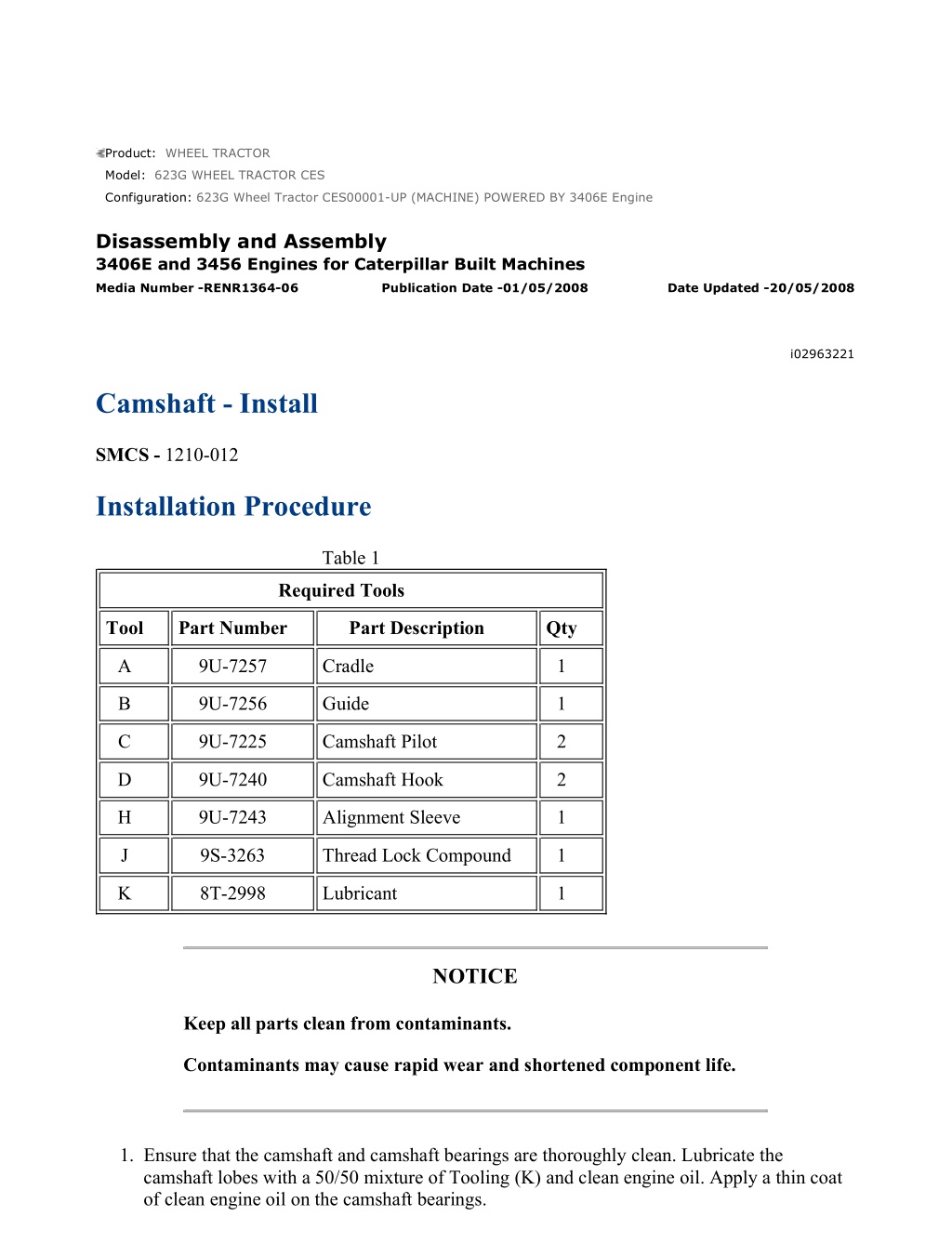
w 1/8(W) Product: WHEEL TRACTOR Model: 623G WHEEL TRACTOR CES Configuration: 623G Wheel Tractor CES00001-UP (MACHINE) POWERED BY 3406E Engine Disassembly and Assembly 3406E and 3456 Engines for Caterpillar Built Machines Media Number -RENR1364-06 Publication Date -01/05/2008 Date Updated -20/05/2008 i02963221 Camshaft - Install SMCS - 1210-012 Installation Procedure Table 1 Required Tools Tool Part Number Part Description Qty A 9U-7257 Cradle 1 B 9U-7256 Guide 1 C 9U-7225 Camshaft Pilot 2 D 9U-7240 Camshaft Hook 2 H 9U-7243 Alignment Sleeve 1 J 9S-3263 Thread Lock Compound 1 K 8T-2998 Lubricant 1 NOTICE Keep all parts clean from contaminants. Contaminants may cause rapid wear and shortened component life. 1. Ensure that the camshaft and camshaft bearings are thoroughly clean. Lubricate the camshaft lobes with a 50/50 mixture of Tooling (K) and clean engine oil. Apply a thin coat of clean engine oil on the camshaft bearings. https://127.0.0.1/sisweb/sisweb/techdoc/techdoc_print_page.jsp?returnurl=/sisweb/sisw... 2021/4/12
w 2/8(W) Illustration 1 g00509797 Illustration 2 g00581441 2. Install Tooling (A) on the cylinder head at Location (Y) . Illustration 3 g01024862 https://127.0.0.1/sisweb/sisweb/techdoc/techdoc_print_page.jsp?returnurl=/sisweb/sisw... 2021/4/12
w 3/8(W) 3. Install Tooling (B) on front housing (7) . Do not tighten the bolts that hold Tooling (B) to front housing (7) at this time. 4. Use Tooling (H) to align Tooling (B) with the camshaft bearings. Tighten the bolts that hold Tooling (B) to front housing (7) . Remove Tooling (H) . Note: Tooling (H) should move freely from the bore of Tooling (B) . Illustration 4 g00581445 5. Install Tooling (C) in the end of camshaft (8) . Note: Rotate the camshaft during installation. This will prevent the camshaft from binding in the camshaft bearings. 6. Use a suitable lifting device in order to position camshaft (8) into Tooling (B) and the cylinder head. The weight of the camshaft is approximately 39 kg (86 lb). Illustration 5 g00581444 https://127.0.0.1/sisweb/sisweb/techdoc/techdoc_print_page.jsp?returnurl=/sisweb/sisw... 2021/4/12
https://www.ebooklibonline.com Hello dear friend! Thank you very much for reading. Enter the link into your browser. The full manual is available for immediate download. https://www.ebooklibonline.com
w 4/8(W) Illustration 6 g00581443 Note: Tooling (C) must be removed before the camshaft can be completely installed in the cylinder head. 7. Remove the lifting device. Rotate the camshaft during installation. Use care not to allow the end of the camshaft and Tooling (C) to drop. Use Tooling (D) to assist in aligning camshaft (8) with the camshaft bearings. 8. Remove Tooling (C) and finish installing camshaft (8) in the bore. 9. Remove Tooling (A) and Tooling (B) . Illustration 7 g00576240 https://127.0.0.1/sisweb/sisweb/techdoc/techdoc_print_page.jsp?returnurl=/sisweb/sisw... 2021/4/12
w 5/8(W) Illustration 8 g00576839 10. Install O-ring seals (5) and (6) in seal assembly (3) . Lubricate seal (6) with Tooling (K) . 11. Install seal assembly (3) . Position adapter (4) . Ensure that the dowel in adapter (4) engages the hole in the camshaft. 12. Position thrust plate (1) . Apply Tooling (J) to bolts (2) . Hold thrust plate (1) in position and install bolts (2) . Evenly tighten bolts (2) until seal assembly (3) and O-ring seal (5) are seated against the cylinder head. Note: Be careful in order to ensure that O-ring seal (5) stays in the groove in seal assembly (3) . End By: a. Install the rocker arms and the rocker shafts. Refer to Disassembly and Assembly, "Rocker Arm and Shaft - Install". b. Install the camshaft gear. Refer to Disassembly and Assembly, "Camshaft Gear - Remove and Install". Alternative Installation Procedure Table 2 Required Tools Tool Part Number Part Description Qty E (1) 177-8001 Sleeve 1 F 177-8002 Adapter 1 G 6L-4697 Bolts 3 J 9S-3263 Thread Lock Compound 1 K 8T-2998 Lubricant 1 ( 1 ) Part of 177-8003 Engine Tool Group https://127.0.0.1/sisweb/sisweb/techdoc/techdoc_print_page.jsp?returnurl=/sisweb/sisw... 2021/4/12
w 6/8(W) NOTICE Keep all parts clean from contaminants. Contaminants may cause rapid wear and shortened component life. 1. Ensure that the camshaft and camshaft bearings are thoroughly clean. Lubricate the camshaft lobes with a 50/50 mixture of Tooling (K) and clean engine oil. Apply a thin coat of clean engine oil on the camshaft bearings. Illustration 9 g01043587 2. Install Tooling (F) on the front of camshaft (9) with Tooling (G) . 3. Install Tooling (E) . 4. Use two technicians to install the camshaft. Carefully slide camshaft (9) into the cylinder head from the rear of the engine. Keep the camshaft level while the camshaft is being installed in the cylinder head. The weight of the camshaft is approximately 39 kg (86 lb). 5. Remove Tooling (F) . https://127.0.0.1/sisweb/sisweb/techdoc/techdoc_print_page.jsp?returnurl=/sisweb/sisw... 2021/4/12
w 7/8(W) Illustration 10 g01043589 6. Install Tooling (F) on the end of the camshaft. 7. Use two technicians to install the camshaft. Carefully slide camshaft (9) into the cylinder head from the rear of the engine. Keep the camshaft level while the camshaft is being installed in the cylinder head. The weight of the camshaft is approximately 39 kg (86 lb). 8. Remove Tooling (F) . Illustration 11 g01043575 9. Position cover (8) on the rear of the cylinder head. Install bolts (7) . Illustration 12 g00576240 https://127.0.0.1/sisweb/sisweb/techdoc/techdoc_print_page.jsp?returnurl=/sisweb/sisw... 2021/4/12
w 8/8(W) Illustration 13 g00576839 10. Install O-ring seals (5) and (6) in seal assembly (3) . Lubricate seal (6) with Tooling (K) . 11. Install seal assembly (3) . Position adapter (4) . Ensure that the dowel in adapter (4) engages the hole in the camshaft. 12. Position thrust plate (1) . Apply Tooling (J) to bolts (2) . Hold thrust plate (1) in position and install bolts (2) . Evenly tighten bolts (2) until seal assembly (3) and O-ring seal (5) are seated against the cylinder head. Note: Be careful in order to ensure that O-ring seal (5) stays in the groove in seal assembly (3) . End By: a. Install the rocker arms and the rocker shafts. Refer to Disassembly and Assembly, "Rocker Arm and Shaft - Install". b. Install the camshaft gear. Refer to Disassembly and Assembly, "Camshaft Gear - Remove and Install". https://127.0.0.1/sisweb/sisweb/techdoc/techdoc_print_page.jsp?returnurl=/sisweb/sisw... 2021/4/12
w 1/4(W) Product: WHEEL TRACTOR Model: 623G WHEEL TRACTOR CES Configuration: 623G Wheel Tractor CES00001-UP (MACHINE) POWERED BY 3406E Engine Disassembly and Assembly 3406E and 3456 Engines for Caterpillar Built Machines Media Number -RENR1364-06 Publication Date -01/05/2008 Date Updated -20/05/2008 i06094319 Camshaft Gear - Remove and Install SMCS - 1210-010-GE Removal Procedure Table 1 Required Tools Tool Part Number Part Description Qty A 9U-6896 Guide Bolt 1 Start By: A. Remove the front cover. Refer to Disassembly and Assembly, "Front Cover - Remove". Illustration 1 g00579965 https://127.0.0.1/sisweb/sisweb/techdoc/techdoc_print_page.jsp?returnurl=/sisweb/sisw... 2021/4/12
w 2/4(W) Illustration 2 g00579966 1. Position the No. 1 piston at the top center of the compression stroke. Refer to Testing and Adjusting, "Finding Top Center Position for No. 1 Piston". 2. Verify that the timing mark on camshaft gear (1) is aligned with Timing Mark (X) on front housing (3) . 3. Remove top bolt (2) from camshaft gear (1) . Install Tooling (A) in place of the bolt. 4. Remove remaining bolts (2) and remove camshaft gear (1) . NOTICE Do not turn the crankshaft or the camshaft while the camshaft gear is removed. If the front gear group is not correctly timed during installation, interference can occur between the pistons and the valves, resulting in damage to the engine. 5. Remove Tooling (A) . Installation Procedure Table 2 Required Tools Tool Part Number Part Description Qty A 9U-6896 Guide Bolt 1 NOTICE Keep all parts clean from contaminants. Contaminants may cause rapid wear and shortened component life. https://127.0.0.1/sisweb/sisweb/techdoc/techdoc_print_page.jsp?returnurl=/sisweb/sisw... 2021/4/12
w 3/4(W) Illustration 3 g00579966 NOTICE Do not turn the crankshaft or the camshaft while the camshaft gear is removed. If the front gear group is not correctly timed during installation, interference can occur between the pistons and the valves, resulting in damage to the engine. 1. Install Tooling (A) in the top hole in the camshaft. 2. Align the hole in the back of camshaft gear (1) with the dowel in the adapter. Install camshaft gear (1) over Tooling (A) . Illustration 4 g00579965 https://127.0.0.1/sisweb/sisweb/techdoc/techdoc_print_page.jsp?returnurl=/sisweb/sisw... 2021/4/12
w 4/4(W) Note: Camshaft timing is critical. The timing mark on the camshaft gear must be aligned with the timing mark on the front cover when the No. 1 piston is at the top center of the compression stroke. Refer to Testing and Adjusting, "Gear Group (Front) - Time". 3. Verify that the timing mark on camshaft gear (1) is aligned with Timing Mark (X) on front housing (3) . Note: If the timing marks are not aligned, remove camshaft gear (1) and rotate the camshaft until the timing marks are aligned. 4. Install bolts (2) . Remove Tooling (A) and install remaining bolt (2) . Illustration 5 g00593987 5. Tighten the bolts in a numeric sequence 1, 4, 2, 5, 3, 6, 1, 4 to a torque of 240 40 N m (175 30 lb ft). 6. Check the backlash between the camshaft gear and the adjustable idler gear. The backlash should be 0.356 0.254 mm (0.014 0.010 inch). Refer to Testing and Adjusting, "Gear Group (Front) - Time" for the backlash adjustment procedure. End By: Install the front cover. Refer to Disassembly and Assembly, "Front Cover - Install". https://127.0.0.1/sisweb/sisweb/techdoc/techdoc_print_page.jsp?returnurl=/sisweb/sisw... 2021/4/12
w 1/3(W) Product: WHEEL TRACTOR Model: 623G WHEEL TRACTOR CES Configuration: 623G Wheel Tractor CES00001-UP (MACHINE) POWERED BY 3406E Engine Disassembly and Assembly 3406E and 3456 Engines for Caterpillar Built Machines Media Number -RENR1364-06 Publication Date -01/05/2008 Date Updated -20/05/2008 i01995165 Camshaft Bearings - Remove SMCS - 1211-011 Removal Procedure Table 1 Required Tools Tool Part Number Part Description Qty 8S-2241 Camshaft Bearing Tool Group 1 8S-8290 Nut 1 8S-8291 Threaded Shaft 1 A (1) 8S-8287 Thrust Bearing Assembly 1 8S-8288 Cone 1 8S-8292 Extension (Short) 2 8S-8293 Extension (Long) 1 9U-7222 Camshaft Bearing Pilot 1 B 8M-8778 Taperlock Stud (1/2 inch - 13 UNC by 1 9/16 inch) 1 C 9U-7223 Alignment Bushing 1 D 9U-7210 Puller Plate 1 ( 1 ) Part of the 8S-2241 Camshaft Bearing Tool Group Start By: A. Remove the camshaft. Refer to Disassembly and Assembly, "Camshaft - Remove". https://127.0.0.1/sisweb/sisweb/techdoc/techdoc_print_page.jsp?returnurl=/sisweb/sisw... 2021/4/12
w 2/3(W) NOTICE Keep all parts clean from contaminants. Contaminants may cause rapid wear and shortened component life. Illustration 1 g01005315 1. Remove bolts (1) from rear cover (2). Inspect the O-ring seal and replace the O-ring seal if the O-ring seal is worn or damaged. https://127.0.0.1/sisweb/sisweb/techdoc/techdoc_print_page.jsp?returnurl=/sisweb/sisw... 2021/4/12
w 3/3(W) Illustration 2 g01034895 2. Remove the No. 7 camshaft bearing (rear). Work from the rear of the engine to the front of the engine. 3. Install the small end of Tooling (B) in the camshaft bearing. 4. Position Tooling (D) on Tooling (A). Install Tooling (A) on Tooling (B) . Note: Tooling (D) is installed on the outside of the cylinder head. Tooling (D) is required in order to remove the No. 7 camshaft bearing from the cylinder head. 5. Use Tooling (A) to remove camshaft bearing (3) from the cylinder head. 6. Remove Tooling (B) from Tooling (A) and remove the camshaft bearing. 7. Repeat Step 3 through Step 6 in order to remove the remaining camshaft bearings. Work from the rear of the engine to the front of the engine. https://127.0.0.1/sisweb/sisweb/techdoc/techdoc_print_page.jsp?returnurl=/sisweb/sisw... 2021/4/12
w 1/5(W) Product: WHEEL TRACTOR Model: 623G WHEEL TRACTOR CES Configuration: 623G Wheel Tractor CES00001-UP (MACHINE) POWERED BY 3406E Engine Disassembly and Assembly 3406E and 3456 Engines for Caterpillar Built Machines Media Number -RENR1364-06 Publication Date -01/05/2008 Date Updated -20/05/2008 i01995166 Camshaft Bearings - Install SMCS - 1211-012 Installation Procedure Table 1 Required Tools Tool Part Number Part Description Qty 8S-2241 Camshaft Bearing Tool Group 1 8S-8290 Nut 1 8S-8291 Threaded Shaft 1 A (1) 8S-8287 Thrust Bearing Assembly 1 8S-8288 Cone 1 8S-8292 Extension (Short) 2 8S-8293 Extension (Long) 1 9U-7222 Camshaft Bearing Pilot 1 B 8M-8778 Taperlock Stud (1/2 inch - 13 UNC by 1 9/16 inch) 1 C 9U-7223 Alignment Bushing 1 D 9U-7210 Puller Plate 1 9U-7213 Backup Plate 1 E 0S-1621 Bolt (1/2 inch - 13 UNC by 1 inch) 1 F 9U-7214 Spacer Plate 1 ( 1 ) Part of the 8S-2241 Camshaft Bearing Tool Group https://127.0.0.1/sisweb/sisweb/techdoc/techdoc_print_page.jsp?returnurl=/sisweb/sisw... 2021/4/12
w 2/5(W) NOTICE Keep all parts clean from contaminants. Contaminants may cause rapid wear and shortened component life. Note: Ensure that the inside of the cylinder head is clean. Inspect the camshaft bore for metal burrs. Put a thin film of clean engine oil on the inside of the camshaft bearing bores and on each camshaft bearing prior to installation. Illustration 1 g01034920 1. Install the No. 7 camshaft bearing (rear), as follows: a. Insert the large end of Tooling (B) into the No. 7 camshaft bore. Position camshaft bearing (3) on Tooling (B) . b. Position Tooling (D) on Tooling (A). Install Tooling (A) in Tooling (B) . c. Position camshaft bearing (3) on Tooling (B). Install Tooling (E) on Tooling (B) . Note: Refer to Specifications, "Cylinder Head" for appropriate information for the orientation of the camshaft bearings in the cylinder head. d. Use Tooling (A) in order to pull camshaft bearing (3) into the camshaft bore. Note: When the chamfer of Tooling (E) contacts the face of the camshaft bore, the camshaft bearing is properly installed. https://127.0.0.1/sisweb/sisweb/techdoc/techdoc_print_page.jsp?returnurl=/sisweb/sisw... 2021/4/12
w 3/5(W) e. Remove Tooling (E) from Tooling (B). Remove Tooling (A) from Tooling (B). Remove Tooling (B) from the cylinder head. Illustration 2 g01034921 2. Install the No. 6 through No. 2 camshaft bearings, as follows: a. Insert the large end of Tooling (B) into the camshaft bore. Note: Use Tooling (C) to align Tooling (A) and Tooling (B) with the camshaft bearing bores. Install Tooling (C) in the inside diameter of any installed camshaft bearing between Tooling (A) and Tooling (B) . b. Install Tooling (A) in Tooling (B). Position camshaft bearing (3) on Tooling (B). Install Tooling (E) on Tooling (B) . Note: Refer to Specifications, "Cylinder Head" for appropriate information for the location and the orientation of the camshaft bearings in the cylinder head. c. Use Tooling (A) in order to pull camshaft bearing (3) into the camshaft bore. Note: When the chamfer of Tooling (E) contacts the face of the camshaft bore, the camshaft bearing is properly installed. d. Remove Tooling (E) from Tooling (B). Remove Tooling (A) from Tooling (B) . e. Remove Tooling (B) and Tooling (C) from the cylinder head. 3. Repeat Step 2 in order to install the No. 6 through No. 2 camshaft bearings. https://127.0.0.1/sisweb/sisweb/techdoc/techdoc_print_page.jsp?returnurl=/sisweb/sisw... 2021/4/12
w 4/5(W) Illustration 3 g01034922 4. Install the No. 1 camshaft bearing (front), as follows: a. Insert the large end of Tooling (B) into the No. 1 camshaft bore. Assemble Tooling (A) and Tooling (C) on Tooling (B) . b. Position camshaft bearing (3) on Tooling (B). Install Tooling (E) and Tooling (F) on Tooling (B) . Note: Refer to Specifications, "Cylinder Head" for appropriate information for the location and the orientation of the camshaft bearings in the cylinder head. Note: Tooling (F) is used to seat the No. 1 camshaft bearing to the correct depth in the camshaft bore. c. Use Tooling (A) in order to pull the No. 1 camshaft bearing into the No. 1 camshaft bore. When the chamfer of Tooling (E) contacts the face of the camshaft bore, the camshaft bearing is properly installed. d. Remove Tooling (E) and Tooling (F) from Tooling (B). Remove Tooling (A) from Tooling (B) . e. Remove Tooling (B) and Tooling (C) from the cylinder head. https://127.0.0.1/sisweb/sisweb/techdoc/techdoc_print_page.jsp?returnurl=/sisweb/sisw... 2021/4/12
w 5/5(W) Illustration 4 g01005315 5. Inspect the O-ring seal. Replace the O-ring seal if the seal is worn or damaged. Position rear cover (2). Install bolts (1). Tighten the bolts to a torque of 13 3 N m (10 2 lb ft). End By: Install the camshaft. Refer to Disassembly and Assembly, "Camshaft - Install". https://127.0.0.1/sisweb/sisweb/techdoc/techdoc_print_page.jsp?returnurl=/sisweb/sisw... 2021/4/12
w 1/4(W) Product: WHEEL TRACTOR Model: 623G WHEEL TRACTOR CES Configuration: 623G Wheel Tractor CES00001-UP (MACHINE) POWERED BY 3406E Engine Disassembly and Assembly 3406E and 3456 Engines for Caterpillar Built Machines Media Number -RENR1364-06 Publication Date -01/05/2008 Date Updated -20/05/2008 i01974881 Engine Oil Pan - Remove and Install SMCS - 1302-010 Removal Procedure NOTICE Keep all parts clean from contaminants. Contaminants may cause rapid wear and shortened component life. NOTICE Care must be taken to ensure that fluids are contained during performance of inspection, maintenance, testing, adjusting and repair of the product. Be prepared to collect the fluid with suitable containers before opening any compartment or disassembling any component containing fluids. Refer to Special Publication, NENG2500, "Caterpillar Tools and Shop Products Guide" for tools and supplies suitable to collect and contain fluids on Caterpillar products. Dispose of all fluids according to local regulations and mandates. https://127.0.0.1/sisweb/sisweb/techdoc/techdoc_print_page.jsp?returnurl=/sisweb/sisw... 2021/4/12
w 2/4(W) Hot oil and hot components can cause personal injury. Do not allow hot oil or hot components to contact the skin. 1. Drain the oil from the engine oil pan into a suitable container for storage or disposal. Illustration 1 g00516605 2. Remove bolts (2) and remove sound suppression panel (1), if equipped. Illustration 2 g00516607 3. Remove bolts (3) that fasten engine oil pan (4) to the cylinder block. 4. Remove engine oil pan (4) . 5. Some engines are equipped with a plate between the engine oil pan and the cylinder block. Remove the bolts and the plate from the cylinder block. Remove the plate gasket. The weight of the plate is approximately 24 kg (53 lb). Installation Procedure https://127.0.0.1/sisweb/sisweb/techdoc/techdoc_print_page.jsp?returnurl=/sisweb/sisw... 2021/4/12
w 3/4(W) Table 1 Required Tools Tool Part Number Part Description Qty A 8T-9022 Silicone Gasket 1 NOTICE Keep all parts clean from contaminants. Contaminants may cause rapid wear and shortened component life. 1. Apply Tooling (A) on the sealing surface of the engine oil pan and on the connecting joints of the front plate, oil pan gasket, cylinder block, and the flywheel housing. Install a new gasket on the engine oil pan. 2. Position a new gasket on the cylinder block and install the plate, if equipped. The weight of the plate is approximately 24 kg (53 lb). Illustration 3 g00516607 3. Position engine oil pan (4) and install bolts (3). Tighten bolts (3) to a torque of 55 10 N m (41 7 lb ft). 4. Tighten the drain plug to a torque of 70 15 N m (52 11 lb ft). https://127.0.0.1/sisweb/sisweb/techdoc/techdoc_print_page.jsp?returnurl=/sisweb/sisw... 2021/4/12
w 4/4(W) Illustration 4 g00516605 5. If the engine is equipped with a sound suppression panel, position sound suppression panel (1) and install bolts (2) . 6. Fill the engine to the correct level with oil. Refer to Operation and Maintenance Manual, "Refill Capacities". https://127.0.0.1/sisweb/sisweb/techdoc/techdoc_print_page.jsp?returnurl=/sisweb/sisw... 2021/4/12
w 1/2(W) Product: WHEEL TRACTOR Model: 623G WHEEL TRACTOR CES Configuration: 623G Wheel Tractor CES00001-UP (MACHINE) POWERED BY 3406E Engine Disassembly and Assembly 3406E and 3456 Engines for Caterpillar Built Machines Media Number -RENR1364-06 Publication Date -01/05/2008 Date Updated -20/05/2008 i05661411 Cylinder Liner - Remove SMCS - 1216-011 Removal Procedure Table 1 Required Tools Tool Part Number Part Description Qty 5P-8665 Cylinder Liner Puller Gp 1 A 6V-9448(1) Cylinder Pack Puller Gp 1 373-1438(2) Cylinder Pack Puller Gp 1 (1)Alternative option to remove liner, piston, and connecting rod as an assembly for 137 mm (5.4 inch) and 140 mm (5.5 inch) bore diameters. (2)Alternative option to remove liner, piston, and connecting rod as an assembly for 145 mm (5.7 inch) bore diameter. Start By: a. Remove the pistons and connecting rods. Refer to Disassembly and Assembly, "Pistons and Connecting Rods - Remove". NOTICE Keep all parts clean from contaminants. Contaminants may cause rapid wear and shortened component life. https://127.0.0.1/sisweb/sisweb/techdoc/techdoc_print_page.jsp?returnurl=/sisweb/sisw... 2021/4/12
w 2/2(W) Illustration 1 g01005579 1. Remove cylinder liner (1) with Tooling (A). https://127.0.0.1/sisweb/sisweb/techdoc/techdoc_print_page.jsp?returnurl=/sisweb/sisw... 2021/4/12
w 1/3(W) Product: WHEEL TRACTOR Model: 623G WHEEL TRACTOR CES Configuration: 623G Wheel Tractor CES00001-UP (MACHINE) POWERED BY 3406E Engine Disassembly and Assembly 3406E and 3456 Engines for Caterpillar Built Machines Media Number -RENR1364-06 Publication Date -01/05/2008 Date Updated -20/05/2008 i07476029 Cylinder Liner - Install SMCS - 1216-012 Installation Procedure Table 1 Required Tools Tool Part Number Part Description Qty B 2P-8260 Cylinder Liner Installer 1 C - P80 Rubber Lubricant 1 NOTICE Keep all parts clean from contaminants. Contaminants may cause rapid wear and shortened component life. 1. Check the cylinder liner projection. Refer to Testing and Adjusting, "Cylinder Liner Projection - Inspect". https://127.0.0.1/sisweb/sisweb/techdoc/techdoc_print_page.jsp?returnurl=/sisweb/sisw... 2021/4/12
w 2/3(W) Illustration 1 g01004993 2. Install liner seals (3) in the respective grooves. 3. Apply Tooling (C) on the cylinder block liner bore surfaces and liner seals (3). 4. Dip filler band (2) in clean engine oil for a moment. Install filler band (2) and install cylinder liner (1) immediately. Illustration 2 g01005003 5. Use Tooling (B) to install cylinder liner (1) in the cylinder block. Ensure that any marks in relation to the cylinder liner projection are in alignment. Note: Refer to Special Instruction, SEHS9564 for more information about cylinder liner installation. https://127.0.0.1/sisweb/sisweb/techdoc/techdoc_print_page.jsp?returnurl=/sisweb/sisw... 2021/4/12
Suggest: If the above button click is invalid. Please download this document first, and then click the above link to download the complete manual. Thank you so much for reading
w 3/3(W) End By: a. Install the pistons and connecting rods. Refer to Disassembly and Assembly, "Pistons and Connecting Rods - Install". https://127.0.0.1/sisweb/sisweb/techdoc/techdoc_print_page.jsp?returnurl=/sisweb/sisw... 2021/4/12
https://www.ebooklibonline.com Hello dear friend! Thank you very much for reading. Enter the link into your browser. The full manual is available for immediate download. https://www.ebooklibonline.com