CASE IH PUMA 155 Tractor Service Repair Manual Instant Download
Please open the website below to get the complete manualnn// n
Download Presentation

Please find below an Image/Link to download the presentation.
The content on the website is provided AS IS for your information and personal use only. It may not be sold, licensed, or shared on other websites without obtaining consent from the author. Download presentation by click this link. If you encounter any issues during the download, it is possible that the publisher has removed the file from their server.
E N D
Presentation Transcript
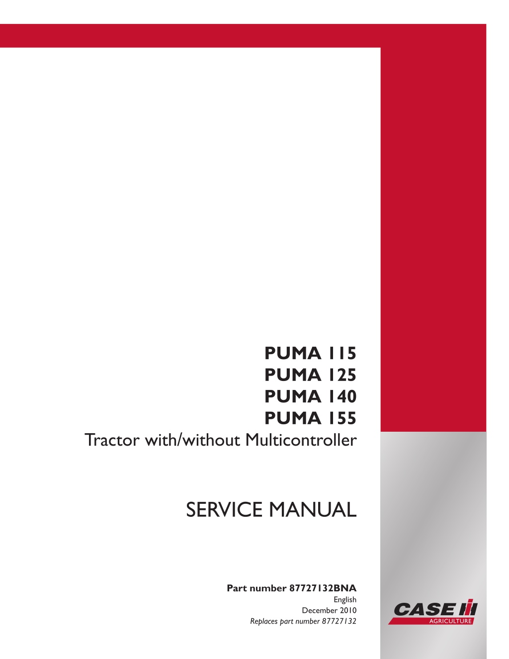
PUMA 115 PUMA 125 PUMA 140 PUMA 155 Tractor with/without Multicontroller SERVICE MANUAL Part number 87727132BNA Printed in U.S.A. English Copyright 2010 CNH America LLC. All Rights Reserved. Case IH is a registered trademark of CNH America LLC. Racine Wisconsin 53404 U.S.A. December 2010 Replaces part number 87727132
SERVICE MANUAL PUMA 115 , PUMA 125 Multicontroller , PUMA 125 , PUMA 140 Multicontroller , PUMA 140 , PUMA 155 Multicontroller , PUMA 155 87727132B 13/04/2010
Contents INTRODUCTION HYDRAULIC-PNEUMATIC-ELECTRICAL-ELECTRONICSYSTEMSA PRIMARY HYDRAULIC POWER SYSTEM............................................... A.10.A PRIMARY HYDRAULIC POWER SYSTEM Closed center mechanical remote valve .... A.10.B PRIMARY HYDRAULIC POWER SYSTEM Electro-hydraulic remote valve..............A.10.C SECONDARY HYDRAULIC POWER SYSTEM........................................... A.12.A PNEUMATIC SYSTEM .................................................................... A.20.A ELECTRICAL POWER SYSTEM ......................................................... A.30.A ELECTRICAL POWER SYSTEM ......................................................... A.30.A ELECTRONIC SYSTEM .................................................................. A.50.A FAULT CODES ............................................................................ A.50.A ENGINE AND PTO IN....................................................................B ENGINE ................................................................................... B.10.A FUEL AND INJECTION SYSTEM......................................................... B.20.A AIR INTAKE SYSTEM..................................................................... B.30.A EXHAUST SYSTEM....................................................................... B.40.A ENGINE COOLANT SYSTEM ............................................................ B.50.A LUBRICATION SYSTEM .................................................................. B.60.A STARTING SYSTEM ...................................................................... B.80.A TRANSMISSION, DRIVE AND PTO OUT.........................................C TRANSMISSION Powershift ..............................................................C.20.E ADDITIONAL REDUCERS Creeper...................................................... C.30.C ADDITIONAL REDUCERS Overdrive.................................................... C.30.D REAR PTO Hydraulic..................................................................... C.40.C TRANSMISSION Semi-Powershift ....................................................... C.20.D AXLES, BRAKES AND STEERING..................................................D FRONT AXLE .............................................................................D.10.A REAR AXLE ...............................................................................D.12.A 2WD-4WD SYSTEM Hydraulic........................................................... D.14.C 87727132B 13/04/2010
https://www.ebooklibonline.com Hello dear friend! Thank you very much for reading. Enter the link into your browser. The full manual is available for immediate download. https://www.ebooklibonline.com
STEERING Hydraulic..................................................................... D.20.C STEERING AutoPilot......................................................................D.20.E SERVICE BRAKE Mechanical ............................................................D.30.B SERVICE BRAKE Hydraulic.............................................................. D.30.C SERVICE BRAKE Pneumatic .............................................................D.30.E PARKING BRAKE Mechanical ............................................................D.32.B BRAKE CONNECTION Hydraulic........................................................ D.34.C SUSPENSION Hydraulic ................................................................. D.40.C WHEELS AND TRACKS Wheels......................................................... D.50.C PARKING BRAKE Electronic............................................................. D.32.D FRAME AND CAB .........................................................................E FRAME Primary frame .................................................................... E.10.B SHIELD.................................................................................... E.20.A USER PLATFORM ........................................................................ E.34.A ENVIRONMENT CONTROL Heating, ventilation and air-conditioning....................E.40.D HITCH AND WORKING TOOL........................................................H HITCH Front hitch .........................................................................H.10.B HITCH Rear hitch......................................................................... H.10.C HITCH Electronic draft control............................................................ H.10.D 87727132B 13/04/2010
INTRODUCTION 87727132B 13/04/2010 1
INTRODUCTION Foreword Technical Information This manual has been produced by a new technical information system. This new system is designed to deliver technical information electronically through CD-ROM and in paper manuals. A coding system called ICE has been developed to link the technical information to other Product Support functions e.g. Warranty. Technical information is written to support the maintenance and service of the functions or systems on a customers machine. When a customer has a concern on his machine it is usually because a function or system on his machine is not working at all, is not working efficiently, or is not responding correctly to his commands. When you refer to the technical information in this manual to resolve that customers concern, you will find all the information classified using the new ICE coding, according to the functions or systems on that machine. Once you have located the technical information for that function or system then you will find all the mechanical, electrical or hydraulic devices, compo- nents, assemblies and sub assemblies for that function or system. You will also find all the types of information that have been written for that function or system, the technical data (specifications), the functional data (how it works), the diagnostic data (fault codes and troubleshooting) and the service data (remove, install adjust, etc.). By integrating this new ICE coding into technical information , you will be able to search and retrieve just the right piece of technical information you need to resolve that customers concern on his machine. This is made possible by attaching 3 categories to each piece of technical information during the authoring process. The first category is the Location, the second category is the Information Type and the third category is the Product: LOCATION - is the component or function on the machine, that the piece of technical information is going to describe e.g. Fuel tank. INFORMATION TYPE - is the piece of technical information that has been written for a particular component or function on the machine e.g. Capacity would be a type of Technical Data that would describe the amount of fuel held by the Fuel tank. PRODUCT - is the model that the piece of technical information is written for. Every piece of technical information will have those 3 categories attached to it. You will be able to use any combination of those categories to find the right piece of technical information you need to resolve that customers concern on his machine. That information could be: the description of how to remove the cylinder head a table of specifications for a hydraulic pump a fault code a troubleshooting table a special tool 87727132B 13/04/2010 3
INTRODUCTION How to Use this Manual This manual is divided into Sections. Each Section is then divided into Chapters. Contents pages are included at the beginning of the manual, then inside every Section and inside every Chapter. An alphabetical Index is included at the end of a Chapter. Page number references are included for every piece of technical information listed in the Chapter Contents or Chapter Index. Each Chapter is divided into four Information types: Technical Data (specifications) for all the mechanical, electrical or hydraulic devices, components and, assemblies. Functional Data (how it works) for all the mechanical, electrical or hydraulic devices, components and assemblies. Diagnostic Data (fault codes, electrical and hydraulic troubleshooting) for all the mechanical, electrical or hydraulic devices, components and assemblies. Service data (remove disassembly, assemble, install) for all the mechanical, electrical or hydraulic devices, com- ponents and assemblies. Sections Sections are grouped according to the main functions or a systems on the machine. Each Section is identified by a letter A, B, C etc. The amount of Sections included in the manual will depend on the type and function of the machine that the manual is written for. Each Section has a Contents page listed in alphabetic/numeric order. This table illustrates which Sections could be included in a manual for a particular product. SECTION A - Distribution Systems B - Power Production C - Power Train D - Travelling E - Body and Structure F - Frame Positioning G - Tool Positioning H - Working Arm J - Tools and Couplers K - Crop Processing L - Field Processing PRODUCT Tractors Vehicles with working arms: backhoes, excavators, skid steers, ..... Combines, forage harvesters, balers, .... Seeding, planting, floating, spraying equipment, .... Mounted equipment and tools, ..... X X X X X X X X X X X X X X X X X X X X X X X X X X X X X X X X X X X X X X X X 87727132B 13/04/2010 4
INTRODUCTION This manual contains these Sections. The contents of each Section are explained over the following pages. Contents INTRODUCTION DISTRIBUTION SYSTEMS POWER PRODUCTION POWER TRAIN TRAVELLING BODY AND STRUCTURE TOOL POSITIONING CROP PROCESSING A B C D E G K Section Contents SECTION A, DISTRIBUTION SYSTEMS This Section covers the main systems that interact with most of the functions of the product. It includes the central parts of the hydraulic, electrical, electronic, pneumatic, lighting and grease lubrication systems. The components that are dedicated to a specific function are listed in the Chapter where all the technical information for that function is included. SECTION B, POWER PRODUCTION This Section covers all the functions related to the production of power to move the machine and to drive various devices. SECTION C, POWER TRAIN This Section covers all the functions related to the transmission of power from the engine to the axles and to internal or external devices and additional Process Drive functions. SECTION D, TRAVELLING This Section covers all the functions related to moving the machine, including tracks, wheels, steering and braking. It covers all the axles both driven axles and non-driven axles, including any axle suspension. SECTION E, BODY AND STRUCTURE This Section covers all the main functions and systems related to the structure and body of the machine. Including the frame, the shields, the operator s cab and the platform. SECTION G, TOOL POSITIONING This Section covers all the functions related to the final and/or automatic positioning of the tool once the tool is posi- tioned using the Working Arm or the machine frame. SECTION K, CROP PROCESSING This Section covers all the functions related to crop processing. 87727132B 13/04/2010 5
SERVICE MANUAL HYDRAULIC - PNEUMATIC - ELECTRICAL - ELECTRONIC SYSTEMS PUMA 115 , PUMA 125 Multicontroller , PUMA 125 , PUMA 140 Multicontroller , PUMA 140 , PUMA 155 Multicontroller , PUMA 155 87727132B 13/04/2010 A
HYDRAULIC - PNEUMATIC - ELECTRICAL - ELECTRONIC SYSTEMS - PRIMARY HYDRAULIC POWER SYSTEM PRIMARY HYDRAULIC POWER SYSTEM - Torque 1 BRJ4969C PRIMARY HYDRAULIC POWER SYSTEM - Special tools PART NUMBER 380000570* DESCRIPTION Tee adaptor 11/16 ORFS female x 11/16 ORFS male x 7/16 UNF female Tee adaptor 7/16 JIC female x 7/16 JIC male x 7/16 UNF female Adaptor M10 banjo x 7/16 UNF female Tee adaptor 9/16 ORFS female x 9/16 ORFS male x 7/16 UNF female Blanking Cap 9/16 ORFS Blanking Cap 7/16 ORFS Adaptor 7/16 UNF female x 1/2 BSP male Adaptor 7/16 UNF female x M12 x 1.5p male Adaptor 7/16 UNF female x M14 x 1.5p male Adaptor M14 banjo x M14 x 1.5p female Tee adaptor 7/16 UNF female x 1/4 BSP hose tail x 1/2 hose 7/16 UNF male Quick release adaptor 380000492* Adaptor M10 x 1.0p x 7/16 UNF female Tee adaptor 1 ORFS female x 1 ORFS male x 7/16 UNF female 380000571* 380000572* 380000573* 380000574* 380000575* 380000576* 380000577* 380000578* 380000579* 380000580* 380000493* 380000517 87727132B 13/04/2010 A.10.A / 4
HYDRAULIC - PNEUMATIC - ELECTRICAL - ELECTRONIC SYSTEMS - PRIMARY HYDRAULIC POWER SYSTEM Blanking Cap 11/16 ORFS Pressure Gauge 0 10 bar Pressure Gauge 0 40 bar (5 off) Pressure Gauge 0 250 bar Remote valve coupling Quick release adaptor Pressure gauge hose 1/8 NPT fitting to attach hose 292246 to gauge Adaptor M10 x 1.0p x 7/16 JIC male (enables use of gauges with 7/16 JIC hoses if used) diagnostic switch Bypass connector Trailer brake fitting Flow Meter 120 ltr/min minimum (procure locally) * Part of hydraulic adaptor kit 380000464 # Part of hydraulic pressure test kit 380000240 Remote Valve check valve removal tool Charge pump pressure test adaptor Lift ram pressure test tee piece 13/16 ORFS Oil cooler pressure test adaptor 380000599* 380000551# 380000552# 380000553# 380000554# 380000543 380000545# 380000544# 380000494 380000488 380000561 380000550# 380002720 380200015 380200012 380200006 87727132B 13/04/2010 A.10.A / 5
HYDRAULIC - PNEUMATIC - ELECTRICAL - ELECTRONIC SYSTEMS - PRIMARY HYDRAULIC POWER SYSTEM Hydraulic pump Variable displacement pump - Torque Refer to PRIMARY HYDRAULIC POWER SYSTEM - Torque (A.10.A) Hydraulic pump Variable displacement pump - General specification Type Variable Displacement Closed Centre Load Sensing Piston Pump 113 l/min (29.85 US gpm) 95 - 105 Ltr/min@ One Remote Valve .25.1 - 27.7 US gal/min. 110 - 113 Ltr/min .29 - 29.8 US gal/min. 6 - 8 bar .( 87 - 116 lbf/in ) 25 - 27 bar (362.500 - 391.500 psi) 210 bar (3045.00 psi) 18 bar (261.00 psi). Maximum Flow @ engine rated speed Minimum Output @ 2200 ERPM (new pump) Minimum Output @ 2200 ERPM (new pump) Charge Pressure (piston pump in standby) Low Standby Pressure High Standby (maximum system) Pressure Regulated Low Pressure 87727132B 13/04/2010 A.10.A / 6
HYDRAULIC - PNEUMATIC - ELECTRICAL - ELECTRONIC SYSTEMS - PRIMARY HYDRAULIC POWER SYSTEM Charge pump - General specification Charge Pump ( 106 Ltr/Min ) Type Charge Pressure Filter Dump Valve Gear Type Pump Crack open @ 6.9 bar ( 100 lbf/in2) Fully Open @ 12.4 bar ( 180 lbf/in2) Minimum 1.6 - 3.4 bar ( 23 - 50 lbf/in2) @ 2100 rev/min and variable flow piston pump On Load Close @ 0.55 - 0.82 bar ( 8 - 12 lbf/in2) Making charge pressure warning light flash Charge Pressure Charge Pressure Switch 87727132B 13/04/2010 A.10.A / 7
HYDRAULIC - PNEUMATIC - ELECTRICAL - ELECTRONIC SYSTEMS - PRIMARY HYDRAULIC POWER SYSTEM PRIMARY HYDRAULIC POWER SYSTEM - Static description The hydraulic systems can be separated into the following circuits :- High Pressure Circuit Hydraulic Lift Assembly. Remote Control Valves. Trailer Brake (Where Fitted) Suspended Front Axle. Front Lift (Where fitted). Steering Circuit Steering Motor and Cylinders Low Pressure Circuit Independent Power Take Off (PTO). Differential Lock Front Wheel Drive engagement Transmission clutch and synchroniser engagement Creeper engagement (Where fitted) Front PTO (Where fitted) 50 kph engagement (Where fitted) Lubrication Circuit PTO Clutch Plates Transmission Clutch Plates. Transmission Shaft Pressure Lube Pump Drive Gear Bearing. Hydraulic Lift Cross Shaft Options/Configurations Hydraulic Pump/ HPL/ Remote Valve Options Less Hydraulic Trailer Brakes With Hydraulic Trailer Brakes Hydraulic Trailer Brake Italy Variable Displacement Pump. EDC 2 Non Configurable 2 Configurable 1 Non Configurable + 2 Configurable 2 Non Configurable + 2 Configurable 2, 3, or 4 Electro hydraulically operated valves Mechanical Remote Valves Electro-Hydraulic Remote Valves Transmission 18 X 6 40KM/H SEMIPOWERSHIFT 18 X 6 35KM/H SEMIPOWERSHIFT 19 X 6 40KM/H SEMIPOWERSHIFT 19 X 6 50KM/H SEMIPOWERSHIFT 17 X 6 30KM/H SEMIPOWERSHIFT 18 X 6 40KM/H FULLPOWERSHIFT 18 X 6 35KM/H FULLPOWERSHIFT 19 X 6 40KM/H FULLPOWERSHIFT 19 X 6 50KM/H FULLPOWERSHIFT 1 Table The high pressure circuit is of the Closed Centre Load Sensing design on all tractor model options fed by a Variable Displacement Pump. Figure 1 shows the variable displacement pump and filter assembly. 87727132B 13/04/2010 A.10.A / 8
HYDRAULIC - PNEUMATIC - ELECTRICAL - ELECTRONIC SYSTEMS - PRIMARY HYDRAULIC POWER SYSTEM 1 BAIL07APH323ASA Closed centre remote valves . There are two types of remote valves available for the closed centre system. Standard fitting are the mechanical remote valves operated via a cable from within the cab and optional are electro hydraulically operated valves, (1) Figure 2, which are operated by electrical switches and have their own in built processor to control oil flow via a solenoid valve. 2 BSE3604B The hydraulic lift Electronic Draft Control valve (EDC valve) is a stack type proportional solenoid operated valve (1) mounted with the remote control valves at the rear of the tractor. (Refer to HITCH Electronic draft control - Static description (H.10.D)) 3 BSE3604A Tractors installed with the electronic draft control hydraulic lift assembly use a unique operator control panel. 87727132B 13/04/2010 A.10.A / 9
HYDRAULIC - PNEUMATIC - ELECTRICAL - ELECTRONIC SYSTEMS - PRIMARY HYDRAULIC POWER SYSTEM 4 BSE2884A (1). Draft sensitivity control knob (3). Height limit control knob (2). Drop rate control knob (4). Slip limit control knob 5 BRL6436B Puma Models from Serial No Z9BL40001 and Z9BL60001 (1). Wheel slip control knob (3).Front hitch height limit control knob (5). Draft sensitivity control knob (2). EHR Function control knob (4). Drop rate control knob (6). Rear hitch height limit control knob 6 BAIL06CCM153ASA (1). Stop adjuster thumbwheel (3). Draft loading wheel (2). Position control Knob (4). Raise/lower switch The raise and lowering functions of the electronic draft control lift system can also be operated from the rear fender switch (1) 87727132B 13/04/2010 A.10.A / 10
HYDRAULIC - PNEUMATIC - ELECTRICAL - ELECTRONIC SYSTEMS - PRIMARY HYDRAULIC POWER SYSTEM 7 BRE1483B The raise and lowering functions of the electronic draft control lift system can also be operated from the rear fender switch (1) 8 BRK5798B Puma Models from Serial No Z9BL40001 and Z9BL60001 The raise and lowering functions of the electronic draft control lift system can also be operated from the rear fender switches (1) and (2) 9 BSE3774A Mechanical remote control valves (1) are also available with electronic draft control. (2). Mechanical remotes are also available with a combination configurable and non configurable valve slices . See Table 1 87727132B 13/04/2010 A.10.A / 11
HYDRAULIC - PNEUMATIC - ELECTRICAL - ELECTRONIC SYSTEMS - PRIMARY HYDRAULIC POWER SYSTEM 10 BSF3967A_430 Located below the Electronic Draft Control valve (Where fitted), is the Hydraulic Power Tapping port (Power Beyond) block.This includes a priority valve and also a low pressure regulating valve (1). This block also has a flange plate which allows the addition of a trailer brake valve. 11 BSE3845A 1. Power Beyond Ports 2. Pressure Relief Valve NOTE: Semi Powershift transmission tractors have two shift buttons plus an extra range button on the reverse side of the handle. CLOSED CENTRE LOAD SENSING HIGH PRESSURE HYDRAULIC CIRCUIT The principal of operation of the closed centre load sensing high pressure hydraulic circuit with variable flow piston pump is to supply oil flow on demand. It also enables simultaneous operation of the trailer brakes, hydraulic lift, remote control valve assemblies and front axle suspension where fitted. The load sensing variable flow piston pump offers significant benefits in reducing the engine power loss that occurs in open centre systems where a high volume of oil, often far in excess of demand, is continuously pumped round the hydraulic circuit even when they are not being operated. A fixed displacement pump (Charge Pump) serves as an initial displacement pump for the variable displacement pump . The variable displacement pump first of all supplies oil to the trailer brake valve (where fitted), the remote valves and electronic draft control valve and a pilot oil supply with lower priority. The highest load pressure is indicated to the flow and compensating valve on the pump via the load sensing line. The flow and compensator valve controls the pump pressure in such a way that it always exceeds the highest load pressure by a pre-set difference. A priority valve for low pressure circuit demand is located in the bottom subplate of the remote valve stack. Tractors fitted with Electro-hydraulic remote valves also have high pressure oil supplied from the variable displacement pump to the top plate of the remote valve stack. The oil passes through the top plate via a small filter and a pressure limiting valve ( 20 - 22 Bar). The oil is then directed to the pilot oil supply of the electro-hydraulic control valve. 87727132B 13/04/2010 A.10.A / 12
HYDRAULIC - PNEUMATIC - ELECTRICAL - ELECTRONIC SYSTEMS - PRIMARY HYDRAULIC POWER SYSTEM 12 BAIL07APH330GSA 1. High Pressure Feed to Electro-Hydraulic Valve Pilot Line 3. Electronic Draft Control Valve 5. Low Pressure Feed 7. Lubrication Manifold 2. Electro-Hydraulic Remote Valves 4. Trailer Brake Valve (Where Fitted) 6. Load Sensing Line 8. Low Pressure Feed to 50 km/h 19th Gear Clutch Manifold 10. Flow and Pressure Compensator Valve 12. Return line from Hydraulic Lift Cylinder 9. Variable Displacement Pump 11. High Pressure Feed to Electro-Hydraulic Remote Valves 13. Feed to trailer brake Coupler The main filter (1) and the charge filter (2) Figure 13 are installed on tractors with variable displacement pump (CCLS system). 1. Main Intake (Suction) Filter 2. Charge Filter 87727132B 13/04/2010 A.10.A / 13
HYDRAULIC - PNEUMATIC - ELECTRICAL - ELECTRONIC SYSTEMS - PRIMARY HYDRAULIC POWER SYSTEM 13 BAIS06CCM055AVA Two valves are located within the filter assembly cap. These are (1) the 0.8 bar (11.600 psi) supplementary lube valve and the 3 bar (43.500 psi) charge pressure bypass valve (2). 14 BRJ5174B High Pressure Hydraulic System, Variable Displacement Pump (CCLS) - Electrical Switches 1. Low Charge Pressure Warning Switch 2. Intake Filter restriction (vacuum) Switch 3. Low Oil Temperature Switch 15 BAIL07APH325ASA Mid-Mount Remote Valves. Optional additional remote valves are mounted under the cab. Connected into the high pressure oil line supplied from the hydraulic pump after the trailer brake valve and operated via a joystick control in the cab. (Refer to Mid-mount remote control valve - Static description (A.10.C)) 87727132B 13/04/2010 A.10.A / 14
HYDRAULIC - PNEUMATIC - ELECTRICAL - ELECTRONIC SYSTEMS - PRIMARY HYDRAULIC POWER SYSTEM 16 BAIL06CCM088ASA Suspended front axle control valve (where fitted) The suspension control valve is located on the right hand side of the tractor. High pressure oil is fed from the power beyond port on the sub plate of the remote valve stack and with the use of processor controlled PWM valves controls the flow of oil to the suspension cylinder (Refer to SUSPENSION Hydraulic - Static description (D.40.C)) 17 BAIL07APH357HSA Front Axle Suspension Cylinder 18 BSE3769A Steering Motor All models use a fixed displacement motor. Also fitted as an option on some models is a Turn Assist valve (1) which is coupled to the steering motor (2) . 87727132B 13/04/2010 A.10.A / 15
HYDRAULIC - PNEUMATIC - ELECTRICAL - ELECTRONIC SYSTEMS - PRIMARY HYDRAULIC POWER SYSTEM 19 BAIL07APH352ASA Steering Cylinders. Receives high pressure oil directly from the steering motor. 20 BSE2868B Load Sensing Shuttle Valve. Located in each remote valve slice, the Electronic Draft Control valve and between the trailer brake valve, front sus- pension valve and mid-mounted valves, where fitted, is the load sensing shuttle valve (2) Figure 21. This allows the function with the highest pressure demand to send sensing pressure to the load sensing valve, Figure 22, on the variable displacement pump. 21 BSB0388A_436 1. Load Sensing Line 2. Pressure Compensator Valve 3. Flow Compensating Valve 4. Valve Body 87727132B 13/04/2010 A.10.A / 16
HYDRAULIC - PNEUMATIC - ELECTRICAL - ELECTRONIC SYSTEMS - PRIMARY HYDRAULIC POWER SYSTEM 22 BAIL07APH326ASA Operation of the closed centre high pressure hydraulic circuit is as follows:- The components in the high pressure hydraulic circuit are connected by their load sensing lines to the hydraulic load sensing valve which controls the output of the hydraulic pump. When the trailer brakes, remote control valves, hydraulic lift or front axle suspension (where fitted) are operating, the load sensing valve on variable flow piston pump, compares the pressure in the component load sense line with the output pressure of the hydraulic pump. If pump output pressure is less than the combined pressure of the load sense line and spring force of the flow con- trol valve, then pump output continues to increase. When circuit demand is satisfied pump pressure overcomes the combined pressure of the load sense line and flow compensating valve spring. This moves the spool in the flow com- pensating valve to the right, allowing control pressure oil to be directed to the variable flow swash plate servo piston, which de-strokes the pump to adjust output to circuit demand. High Pressure oil is fed to a subplate at the bottom of the remote valve stack where it is directed to the Trailer Brake valve which has priority for safety reasons. The oil is then redirected to the Electronic Draft Control Valve and the Electro-Hydraulic Remote Valves. Within the subplate is a pressure compensating valve which diverts the oil to the low pressure system at a pressure of 18 bar (261.00 psi). High Pressure oil is also fed to the top of the Remote Valve stack through an end plate which incorporates a pressure limiting valve and this supplies oil at 20 - 22 bar to the pilot line galleries in the Electro-Hydraulic Remote Valves. Surplus oil from the charge pump to the variable displacement pump is fed past the 0.8 bar valve and boosts the pressure in the lubrication circuit. The trailer brake valve is located on the sub plate of the remote valve stack. The valve diverts oil pressure to the trailer brakes whenever the brake pedals are depressed. The trailer brake has absolute priority over other services in the circuit. 23 BAIL07APH327ASA The remote valves are available as two, three or four valves per tractor. The valves can be double-acting with float and kick out. Double acting convertible to single-acting with float. Double acting convertible to single-acting. 87727132B 13/04/2010 A.10.A / 17
HYDRAULIC - PNEUMATIC - ELECTRICAL - ELECTRONIC SYSTEMS - PRIMARY HYDRAULIC POWER SYSTEM 24 BSE3664A_442 25 BAIL07APH328ASA When the oil is cold and pressure differential across the oil cooler is higher than 6 bar ( 87 lbf/in2) the cooler by-pass valve (1) located in the transmission top cover will operate to ensure that adequate flow to the lubrication circuit is maintained. This feature of diverting oil from the cooler assists in aiding a rapid warm up of oil in cold weather con- ditions. The steering pump / steering return oil is directed through the oil cooler at the front of the tractor and is limited to a maximum pressure of 5.59 bar (81.06 psi)) by the lubrication relief valve located in the transmission top cover. 87727132B 13/04/2010 A.10.A / 18
HYDRAULIC - PNEUMATIC - ELECTRICAL - ELECTRONIC SYSTEMS - PRIMARY HYDRAULIC POWER SYSTEM Power beyond - Overview 1 BRL6472B 1.Load sensing port M14 3.Low pressure return port 3/4 BSP fitting 2.Pressure port M22 x 1.5/15.5 4.Return oil line M27 x 2/19 87727132B 13/04/2010 A.10.A / 19
HYDRAULIC - PNEUMATIC - ELECTRICAL - ELECTRONIC SYSTEMS - PRIMARY HYDRAULIC POWER SYSTEM Hydraulic pump - Static description The variable flow closed centre load sensing hydraulic pump assembly is mounted on the right hand side of the rear axle centre housing and contains within its body two hydraulic pumps See Figure 1. A charge pump of the gear type to supply oil at a charge pressure of 3 bar ( 44 lbf/in2) to a variable flow closed centre load sensing hydraulic piston pump. A variable flow closed centre load sensing piston type hydraulic pump supplying oil to the high pressure circuits for operation of:- Trailer Brake (Where fitted) Hydraulic Lift Assembly Remote Control Valves Front Axle Suspension (Where fitted) Front Lift (Where fitted) Mid Mount remote valves (Where fitted) Principal of Operation Both pumping elements are driven by a live drive gear train directly connected to the PTO clutch input drive shaft and driven by the engine flywheel. The operating principal of the fixed displacement gear pump is to provide a constant oil flow directly related to the rotation speed of the pump. The operating principal of a variable flow piston pump is to provide oil flow on demand and minimises the engine power absorbed in driving the hydraulic pump when the hydraulic circuits do not require maximum pump flow. The variable flow piston pump in hydraulic systems therefore has distinct power loss advantages over fixed displace- ment gear type pumps, which continually provide oil flow and absorb engine power even when the hydraulic circuits do not require the total pump output. Variable Displacement Piston Pump (Refer to Hydraulic pump Variable displacement pump - Sectional view (A.10.A)) The major components of the variable flow piston pump with closed centre load sensing are:- A nine element pumping head. A plate mechanism (swash plate) to adjust piston stroke and corresponding pump output. A load sensing valve which monitors the requirements of the hydraulic circuits and signals the pump to increase or decrease hydraulic oil flow accordingly. The nine element pumping head is cylindrical in shape and has nine barrels, into each of which, is installed a piston. On the end of each piston is pressed a slipper which always remains in contact with the face of the swash plate located at the front of the pumping head. The drive shaft, which is driven by the pump drive gear, rotates the pumping head. As the pumping head rotates, the pistons move in and out of their barrels, following the contour of the swash plate. For every revolution of the drive shaft each piston completes one pumping cycle. The swash plate, which does not rotate but pivots about the front of the pumping head, is the control mechanism that limits the stroke of each piston and works in conjunction with the pressure and flow compensating valves in the load sensing line. As the pumping head rotates each barrel passes over the inlet and then the outlet ports of the pump. During the inlet cycle for each piston and barrel, oil is pumped into the barrel pushing the piston forward so that it always remains in contact with the swash plate. The stroke of each piston and volume of oil charged into its barrel is therefore dependent on the angle of the swash plate. After a piston and barrel has completed the inlet stroke, further rotation of the head aligns the barrel with the outlet port. Oil within the barrel is then forcibly ejected by the piston through the exhaust port to the hydraulic circuits. 87727132B 13/04/2010 A.10.A / 20
HYDRAULIC - PNEUMATIC - ELECTRICAL - ELECTRONIC SYSTEMS - PRIMARY HYDRAULIC POWER SYSTEM 1 BAIL07APH329FSA Variable Displacement Hydraulic Pump Installation 1 High Pressure Feed to Remote Valve Stack 3 Variable Displacement Pump 5 Filter Restriction Switch 7 Charge Pressure Filter 9 Pressure Switch Manifold 11 Brake Lubrication Hose 2 Load Sensing Valve 4 Intake Filter 6 Low Oil Temperature Switch 8 Charge Pump 10 Charge Pressure Switch 12 Pilot Feed to Electro Hydraulic Remotes (Where fitted) The location of the principal components in the hydraulic pump assembly are identified above. These items are shown on the hydraulic circuit diagrams which describe the operating modes of the pump. The principal function of the valves and switches is as follows:- Intake Filter and Restriction Switch (5) Oil for both the charge and steering pump is drawn from the rear axle centre housing via the intake filter (4). The filter incorporates a by-pass valve, which is an integral part of the replaceable filter and it is therefore essential that the correct filter is installed at every filter change. When the filter is blocked the oil filter restriction vacuum switch (5) is activated and illuminates the oil filter restriction warning light on the instrument panel. Because oil is more viscous (thicker) when cold and can falsely indicate that the filter requires servicing a low tem- perature oil switch (6) is also used in the filter restriction circuit. This switch ensures that the warning light will not operate if the oil temperature is less than 40 C. Charge Pump (8) The charge pump ( Refer to Charge pump - Exploded view (A.10.A) supplies oil at a charge pressure of 3 bar ( 44 lbf/in2 to the variable flow closed centre load sensing pump. Low Charge Pressure Switch (6) 87727132B 13/04/2010 A.10.A / 21
HYDRAULIC - PNEUMATIC - ELECTRICAL - ELECTRONIC SYSTEMS - PRIMARY HYDRAULIC POWER SYSTEM The low charge pressure switch will cause a light to Flash on the instrument cluster whenever the charge pressure is less than 0.75 bar ( 11 lbf/in2) Charge Pressure Filter Dump Valve (Refer to (14) Charge pump - Exploded view (A.10.A)) The charge pressure filter dump valve is a safety relief valve for relieving excess pressure on the charge pump should the filter be restricted. This valve will start to operate if the charge pressure exceeds 6 bar ( 87 lbf/in2). Charge Pressure Valve The charge pressure valve diverts excess oil supplied by the charge pump and not required by the variable flow piston pump to the inlet port of the steering and lubrication circuit pump. This valve starts to operate at a pressure of 1 bar ( 14.5 lbf/in2) and when fully open limits the charge pressure circuit oil to 3 bar ( 44 lbf/in2) . Flow and Pressure Compensating Valves (Refer to Compensator - Exploded view (A.10.A)) Output from the variable flow piston pump is determined by adjusting the angle of the swash plate in the pump. The flow compensating valve senses the circuit operating pressure and adjusts the swash plate angle to control pump output. If pump output and circuit pressure rises to 210 bar (3045.00 psi) the pressure compensating valve overrides the flow compensating valve and adjusts the swash plate angle to limit maximum system pressure. 87727132B 13/04/2010 A.10.A / 22
MORE MANUALS: https://www.ebooklibonline.com/ Suggest: If the above button click is invalid. Please download this document first, and then click the above link to download the complete manual. Thank you so much for reading
HYDRAULIC - PNEUMATIC - ELECTRICAL - ELECTRONIC SYSTEMS - PRIMARY HYDRAULIC POWER SYSTEM Hydraulic pump - Dynamic description Refer to Figure 1. The charge pressure pump draws oil through the charge pump inlet filter. Oil drawn by the charge pump flows through the charge pressure filter to the variable flow piston pump and also through the charge pressure valve to the inlet port of the steering pump. Because output from the charge pump can exceed the combined demand of the steering and variable displacement pumps an open gallery between the inlet side of the charge and steering pumps allows excess flow to the inlet side of the steering pump to be returned to the inlet side port of the charge pump. The variable flow closed centre load sensing hydraulic pump operates progressively in 5 modes:- Generating Low Pressure Standby pressure Low Pressure Standby High Pressure Circuit Maximum Demand High Pressure Circuit Low Demand Maximum System Pressure (High Pressure Standby) A. Load Sensing Line from High pressure circuit components. B. Return to Reservoir from flow and pressure compensating valves. C. Gallery to Swash Plate servo piston from flow and compensating valves D. System Pressure sensing gallery to flow and pressure compensating valves E. System pressure supply to low pressure regulating valve F. Regulated Low pressure oil supply G. System pressure outlet from low pressure regulating valve H. Low pressure regulating valve spool sensing gallery 87727132B 13/04/2010 A.10.A / 23
https://www.ebooklibonline.com Hello dear friend! Thank you very much for reading. Enter the link into your browser. The full manual is available for immediate download. https://www.ebooklibonline.com














![Property Settlements in Family Law: Case Study of Stamatou & Stamatou [2022] FedCFamC1F 241](/thumb/63303/property-settlements-in-family-law-case-study-of-stamatou-stamatou-2022-fedcfamc1f-241.jpg)


