CASE CX800 Tier 3 Crawler Excavator Service Repair Manual Instant Download
Please open the website below to get the complete manualnn//

Download Presentation

Please find below an Image/Link to download the presentation.
The content on the website is provided AS IS for your information and personal use only. It may not be sold, licensed, or shared on other websites without obtaining consent from the author. Download presentation by click this link. If you encounter any issues during the download, it is possible that the publisher has removed the file from their server.
E N D
Presentation Transcript
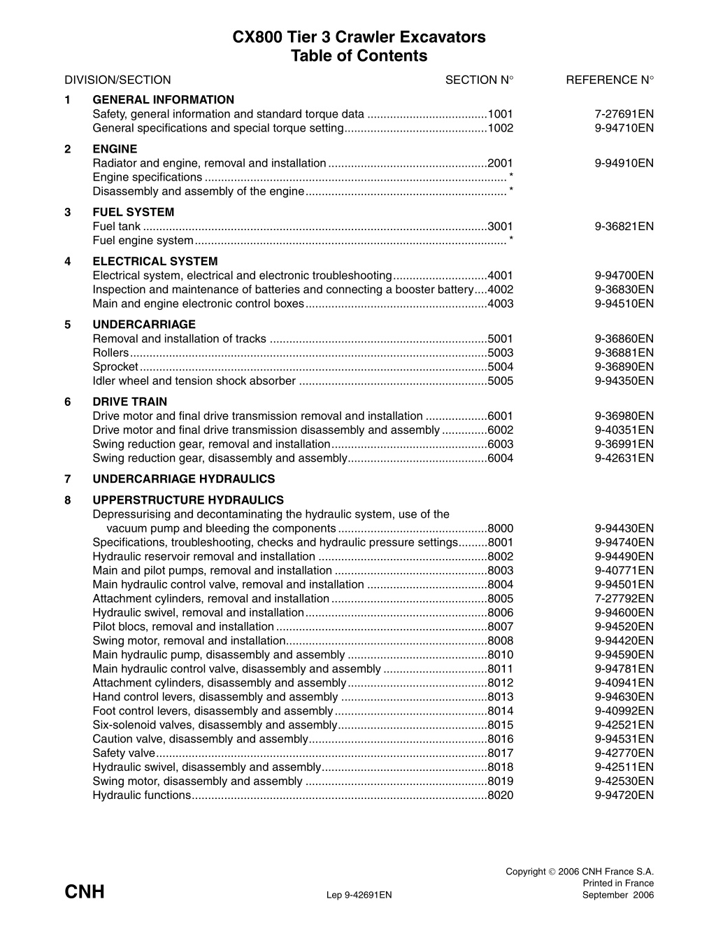
CX800 Tier 3 Crawler Excavators Table of Contents SECTION N REFERENCE N DIVISION/SECTION 1 GENERAL INFORMATION Safety, general information and standard torque data .....................................1001 General specifications and special torque setting............................................1002 7-27691EN 9-94710EN 2 ENGINE Radiator and engine, removal and installation.................................................2001 Engine specifications.............................................................................................* Disassembly and assembly of the engine..............................................................* 9-94910EN 3 FUEL SYSTEM Fuel tank..........................................................................................................3001 Fuel engine system................................................................................................* 9-36821EN 4 ELECTRICAL SYSTEM Electrical system, electrical and electronic troubleshooting.............................4001 Inspection and maintenance of batteries and connecting a booster battery....4002 Main and engine electronic control boxes........................................................4003 9-94700EN 9-36830EN 9-94510EN 5 UNDERCARRIAGE Removal and installation of tracks ...................................................................5001 Rollers..............................................................................................................5003 Sprocket...........................................................................................................5004 Idler wheel and tension shock absorber ..........................................................5005 9-36860EN 9-36881EN 9-36890EN 9-94350EN 6 DRIVE TRAIN Drive motor and final drive transmission removal and installation ...................6001 Drive motor and final drive transmission disassembly and assembly..............6002 Swing reduction gear, removal and installation................................................6003 Swing reduction gear, disassembly and assembly...........................................6004 9-36980EN 9-40351EN 9-36991EN 9-42631EN 7 UNDERCARRIAGE HYDRAULICS 8 UPPERSTRUCTURE HYDRAULICS Depressurising and decontaminating the hydraulic system, use of the vacuum pump and bleeding the components..............................................8000 Specifications, troubleshooting, checks and hydraulic pressure settings.........8001 Hydraulic reservoir removal and installation ....................................................8002 Main and pilot pumps, removal and installation ...............................................8003 Main hydraulic control valve, removal and installation .....................................8004 Attachment cylinders, removal and installation................................................8005 Hydraulic swivel, removal and installation........................................................8006 Pilot blocs, removal and installation.................................................................8007 Swing motor, removal and installation..............................................................8008 Main hydraulic pump, disassembly and assembly ...........................................8010 Main hydraulic control valve, disassembly and assembly................................8011 Attachment cylinders, disassembly and assembly...........................................8012 Hand control levers, disassembly and assembly .............................................8013 Foot control levers, disassembly and assembly...............................................8014 Six-solenoid valves, disassembly and assembly..............................................8015 Caution valve, disassembly and assembly.......................................................8016 Safety valve......................................................................................................8017 Hydraulic swivel, disassembly and assembly...................................................8018 Swing motor, disassembly and assembly ........................................................8019 Hydraulic functions...........................................................................................8020 9-94430EN 9-94740EN 9-94490EN 9-40771EN 9-94501EN 7-27792EN 9-94600EN 9-94520EN 9-94420EN 9-94590EN 9-94781EN 9-40941EN 9-94630EN 9-40992EN 9-42521EN 9-94531EN 9-42770EN 9-42511EN 9-42530EN 9-94720EN Copyright 2006 CNH France S.A. Printed in France September 2006 CNH Lep 9-42691EN
DIVISION/SECTION SECTION N REFERENCE N Fan motor, removal and installation .................................................................8022 Fan motor, disassembly and assembly............................................................8023 Fan pump, removal, disassembly, assembly and installation...........................8024 Hydraulic component functions........................................................................8030 9-94660EN 9-94670EN 9-94680EN 9-94130EN 9 UPPERSTRUCTURE Upperstructure, turntable and counterweight...................................................9002 Boom, dipper and bucket .................................................................................9003 Seat and seat belt............................................................................................9004 Cab and cab equipment...................................................................................9005 Air conditioning troubleshooting.......................................................................9006 Air conditioning unit disassembly and assembly..............................................9007 Air conditioning servicing.................................................................................9008 Air conditioning components............................................................................9009 Removal and installation attachment, counterweight and side fram................9010 Large format hydraulic schematic.................................................................Pocket Large format electrical schematic.................................................................Pocket 9-42551EN 9-42621EN 9-40960EN 9-94650EN 7-xxxxxFR 9-94640EN 7-xxxxxFR 7-xxxxxFR 9-94730EN 87520431 9-93930 * Consult the Engine Service Manual Sections to be distributed at a later date NOTE: CNH Company reserves the right to make changes in the specifi- cation and design of the machine without prior notice and without incur- ring any obligation to modify units previously sold. The description of the models shown in this manual has been made in accordance with the technical specifications known as of the date of design of this document. Lep 9-42691EN Edition 09-06
1001 Section 1001 SAFETY, GENERAL INFORMATION AND TORQUE SPECIFICATIONS Copyright 2006 CNH France S.A. Printed in France February 2006 CNH Lep 7-27691EN
https://www.ebooklibonline.com Hello dear friend! Thank you very much for reading. Enter the link into your browser. The full manual is available for immediate download. https://www.ebooklibonline.com
1001-3 GENERAL INFORMATION Cleanning Gears Clean all metal parts except bearings, in a suitable cleaning solvent or by steam cleaning. Do not use caustic soda for steam cleaning. After cleaning, dry and put oil on all parts. Clean oil passages with compressed air. Clean bearings in a suitable cleaning solvent, dry the bearings completely and put oil on the bearings. Check all gears for wear and damage. Replace gears that have wear or damage. Oil seals, O-rings and gaskets Always install new oil seals, O-rings and gaskets. Put petroleum jelly on seals and O-rings. Shafts Inspection Check all shafts that have wear or damage. Check the bearing and oil seal surfaces of the shafts for damage. Check all parts when the parts are disassembled. Replace all parts that have wear or damage. Small scoring or grooves can be removed with a hone or crocus cloth. Complete a visual inspection for indications of wear, pitting and the replacement of parts necessary to prevent early failures. Service parts Always install genuine Case service parts. When ordering refer to the Parts Catalog for the correct part number of the genuine Case replacement items. Failures due to the use of other than genuine Case replacement parts are not covered by warranty. Bearings Check bearings for easy action. If bearings have a loose fit or rough action replace the bearing. Wash bearings with a suitable cleaning solvent and permit to air dry. DO NOT DRY BEARINGS WITH COMPRESSED AIR. Lubrication Only use the oils and lubricants specified in the Operator s or Service Manuals. Failures due to the use of non-specified oils and lubricants are not covered by warranty. Needle bearings Before you press needle bearings in a bore always remove any metal protrusions in the bore or edge of the bore. Before you press bearings into position put petroleum jelly on the inside and outside diameter of the bearings. Lep 7-27691EN Issued 02-06
1001-4 SAFETY This symbol means ATTENTION! BECOME ALERT! YOUR SAFETY IS INVOLVED. The message that follows the symbol contains important information about safety. Carefully read the message. Make sure you fully understand the causes of possible injury or death. ! To prevent injury always follow the Warning, Caution and Danger notes in this section and throughout the manual. WARNING: Before starting engine, study Operator s Manual safety messages. Read all safety signs on machine. Clear the area of other persons. Learn and practice safe use of controls before operating. It is your responsibility to understand and follow manufacturers instructions on machine operation, service and to observe pertinent laws and regulations. Operator s and Service Manuals may be obtained from your Case dealer. Put the warning tag shown below on the key for the keyswitch when servicing or repairing the machine. One warning tag is supplied with each machine. Additional tags Part Number 331-4614 are available from your service parts supplier ! . WARNING: Read the operator s manual to familiarize yourself with the correct control functions. ! WARNING: If you wear clothing that is too loose or do not use the correct safety equipment for your job, you can be injured. Always wear clothing that will not catch on objects. Extra safety equipment that can be required includes hard hat, safety shoes, ear protection, eye or face protection, heavy gloves and reflector clothing. WARNING: Operate the machine and equipment controls from the seat position only. Any other method could result in serious injury. ! ! WARNING: This is a one man machine, no riders allowed. ! WARNING: When working in the area of the fan belt with the engine running, avoid loose clothing if possible, and use extreme caution. ! WARNING: When doing checks and tests on the equipment hydraulics, follow the procedures as they are written. DO NOT change the procedure. ! WARNING: When putting the hydraulic cylinders on this machine through the necessary cycles to check operation or to remove air from a circuit, make sure all people are out of the way. ! Lep 7-27691EN Issued 02-06
1001-5 WARNING: When servicing or repairing the machine, keep the shop floor and operator s compartment and steps free of oil, water, grease, tools, etc. Use an oil absorbing material and/or shop cloths as required. Use safe practices at all times. WARNING: Use insulated gloves or mittens when working with hot parts. ! ! WARNING: Lower all attachments to the ground or use stands to safely support the attachments before you do any maintenance or service. ! WARNING: Some components of this machine are very heavy. Use suitable lifting equipment or additional help as instructed in this Service Manual. ! WARNING: Pin sized and smaller streams of hydraulic oil under pressure can penetrate the skin and result in serious infection. If hydraulic oil under pressure does penetrate the skin, seek medical treatment immediately. Maintain all hoses and tubes in good condition. Make sure all connections are tight. Make a replacement of any tube or hose that is damaged or thought to be damaged. DO NOT use your hand to check for leaks, use a piece of cardboard or wood. WARNING: Engine exhaust fumes can cause death. If it is necessary to start the engine in a closed place, remove the exhaust fumes from the area with an exhaust pipe extension. Open the doors and get outside air into the area. ! ! WARNING: When the battery electrolyte is frozen, the battery can explode if (1), you try to charge the battery, or (2), you try to jump start and run the engine. To prevent the battery electrolyte from freezing, try to keep the battery at full charge. If you do not follow these instructions, you or others in the area can be injured. WARNING: When removing hardened pins such as a pivot pin, or a hardened shaft, use a soft head (brass or bronze) hammer or use a driver made from brass or bronze and a steel head hammer. ! ! WARNING: When using a hammer to remove and install pivot pins or separate parts using compressed air or using a grinder, wear eye protection that completely encloses the eyes (approved goggles or other approved eye protectors). ! WARNING: Use suitable floor (service) jacks or chain hoist to raise wheels or tracks off the floor. Always block machine in place with suitable safety stands. ! Lep 7-27691EN Issued 02-06
1002-30 15 12 13 16 14 17 8 19 24 7 1 2 21 18 9 10 22 23 5 4 6 11 20 3 700-2-01-00-15A 23 22 3 1 19 7 4 2 6 5 700-2-01-01-44AA Lep 9-94710EN Issued 06-06
2001 Section 2001 RADIATOR, OIL-COOLER, INTER COOLER, FUEL COOLER AND ENGINE REMOVAL AND INSTALLATION Copyright 2006 CNH France S.A. Printed in France September 2006 CNH Lep 9-94910EN
2001-3 RADIATOR, OIL-COOLER, INTER COOLER AND FUEL COOLER Before carrying out any operation on the machine, perform the following operations in the order shown: - Park the machine on hard, flat ground. - Lower the attachment to the ground. - Shut down the engine. - Remove the starter switch key. - Make sure that pressure in the hydraulic system has been completely released (see Operator s Manual). WARNING: When the machine is working, the engine components and the hydraulic pump reach a high temperature. To avoid being burnt by hot metal or scalded by high temperature water or oil, allow the machine to cool down before starting any servicing operation. ! NOTE: For the removal and the installation of the radiator, oil cooler, inter cooler and fuel cooler refer to the figure 1, page 10. Removal STEP 1 Drain the cooling system (see Operator s Manual). STEP 2 Release pressure in the hydraulic reservoir to allow the vacuum pump to be mounted (see Section 8000). Installation When installing, proceed in the reverse order from that of removal. Before operating the machine: - Check the oil level in the hydraulic reservoir. Top up if necessary. - Check the hydraulic fluid cooling circuit for leaks. - Fill and bleed the engine cooling system (see Oper- ator s Manual). - Check the engine cooling system for leaks. Lep 9-94910EN Issued 09-06
2001-4 ENGINE Description B51 B47 B52 B1 B49 B50 B21 B3 B1 Coolant temperature sensor B3 Fuel temperature sensor B21 Engine oil pressure switch B47 Boost pressure sensor B49 Crankshaft position sensor (or engine speed sensor (flywheel mounted)) B50 Camshaft position sensor (or G sensor: cylinder recognition sensor (detects rotation of cam shaft)) B51 Boost temperature sensor B52 Common rail pressure sensor Lep 9-94910EN Issued 09-06
2001-5 Removal and installation STEP 4 NOTE: For the removal and the installation of the engine refer to the figure 1, page 10. STEP 1 1 CD01D131 Remove the screws (1) from the compressor and put it away from the engine. STEP 5 JS00163A Park the machine on hard, flat ground. Lower the attachment to the ground. STEP 2 M15 Release pressure in the hydraulic system and in the hydraulic reservoir (see Section 8000). STEP 3 B53 1 CRPH06A031A Disconnect the exhaust gas recirculation valve posi- tion sensor (B53) from the exhaust gas recirculation motor (M15). STEP 6 B51 B47 CT05L063 Disconnect the earth cable (-) (1) from the battery. CRPH06A033A Label and disconnect the boost temperature sensor (B51) and the boost pressure sensor (B47). Lep 9-94910EN Issued 09-06
2001-6 STEP 7 STEP 10 B1 CRPH06A034A CRPH06A038A Label and disconnect the electrical connections from the injectors. STEP 8 Label and disconnect the coolant temperature switch (B1). STEP 11 M1 R1 CRPH06A035A CD00J031 Label and disconnect the electrical supply to the glow plug (R1). STEP 9 Label and disconnect the electrical connections to the starter motor (M1). Remove the earth cable at the engine end. STEP 12 B52 B3 CRPH06A037A Label and disconnect the connections from the com- mon rail pressure sensor (B52). CRPH06A039A Label and disconnect the electrical connections of the fuel temperature sensor (B3). Lep 9-94910EN Issued 09-06
2001-7 STEP 13 Y34 B50 Y33 CRPH06A043A Label and disconnect the camshaft position sensor (B50). STEP 16 CRPH06A040A Label and disconnect the supply pump valve PCV1 (Y33) and the supply pump valve PCV2 (Y34). STEP 14 B49 G2 CRPH06A041A CRPH06A044A Label and disconnect the electrical connections to the alternator (G2). STEP 15 Label and disconnect the crankshaft position sensor (B49). STEP 17 Remove all the clips, etc. which attach the electrical harnesses to the engine and move out of the way. STEP 18 Install a suitable lifting device on the engine lifting rings (for the weight of the engine, see Section 1002). STEP 19 Remove the engine retaining hardware. B21 NOTE: When installing, make a visual inspection of the condition of the rubber flexible mountings and change them if necessary. Tighten the engine retain- ing screws to the torque specified in Section 1002. STEP 20 CRPH06A042A Label and disconnect the engine oil pressure sensor (B21). When there is nothing interfering with the removal of the engine, raise the engine carefully and install it on a suitable repair bench. Lep 9-94910EN Issued 09-06
2001-8 STEP 21 Refer to Section 8003 and remove the hydraulic pump. STEP 22 Remove the silencer assembly with his bracket from the engine. NOTE: When installing, tighten the screws to a torque of 109 to 127 Nm. NOTE: When installing the engine in the machine, proceed in the reverse order from removal. Before operating the machine, carry out the following operations: - Bleed and prime the fuel system (see Operator s Manual). - Fill and bleed the engine cooling system (see Oper- ator s Manual). - Check the hydraulic, fuel and cooling systems for leaks. - Check the oil level in the hydraulic reservoir. Top up if necessary. Lep 9-94910EN Issued 09-06
3001-3 FUEL TANK Removal STEP 1 STEP 9 Remove and seal all hoses of the fuel tank filler pump and remove the fuel tank filler pump. STEP 10 Remove the screws (8) and the protective plate (D) from on top of the fuel tank (1). Remove the screws (11) and the protective plate (C) from on top of the fuel tank (1). Remove the screws (10) and the protective plate (B) from on top of the fuel tank (1). STEP 11 Remove the front storage box (7). STEP 12 JS00163A Park the machine on hard, flat ground. Lower the attachment to the ground. STEP 2 Attach labels on the hoses of the fuel tank and remove them. STEP 13 Reduce the engine speed to idle for 30 seconds, then shut down the engine. STEP 3 Shift the plastic protection (13) from the fuel sensor (14). Remove the retaining screws (15) then the fuel sensor (14) as well as the seal. STEP 14 Turn the ignition key to ON without starting the engine. STEP 4 Remove the screws (17) from the fuel tank (1), and the spacer (18). STEP 15 Attach a DO NOT OPERATE tag to the ignition key in the cab. STEP 5 Remove the fuel tank (1) using a hoist. Remove the shims (22). STEP 16 NOTE: The numbers within brackets refer to the fig- ures on pages 5 and 6. Remove the access panel (A) under the fuel tank (1). STEP 6 See the operator's manual for removing the fuel filter. Open the filling plug (2) of the tank (1). Bleed the remaining fuel using the valve (3) then remove the latter. Remove the filter (19) and the fuel gauge (20). STEP 7 Remove the retaining screw (4) of the access ramp (5) then remove the access ramp (5). Remove the retaining screw (6) of the access ramp (12) then remove the access ramp (12). Remove the retaining screw (20) of the access ramp (21) then remove the access ramp (21). STEP 8 Attach identification tags on the electrical connec- tions of the fuel tank filler pump and disconnect them. Lep 9-36821EN Issued 09-06
3001-4 Installation STEP 8 NOTE: The numbers within brackets refer to the fig- ures on pages 5 and 6. STEP 1 Install the access ramp (21) using the retaining screws (20). Using a hoist, position the fuel tank (1) on the machine. STEP 2 Install the access ramp (12) using the retaining screws (6). Install the access ramp (5) using the retaining screws (4). STEP 9 Install the shims (22) as well as the spacer (18) and the screws (17), tighten the screws to the torque specified on the section 1002. Install and tighten the valve (3). STEP 3 Fill the fuel tank (see the operator's manual) and make sure that there are no leaks. STEP 10 Install a new seal, then the fuel probe (14) using the five screws (15), reposition the plastic protection cor- rectly (13). STEP 4 Reinstall the protective plate (A) under the fuel tank (1). Install the hoses by taking help of the labels attached during removal. Tighten using retaining clips. STEP 5 Install the front storage box. STEP 6 Install the fuel tank filler pump and connect al hoses. STEP 7 Install the protective plate (B) on top of the fuel tank (1). Tighten the screws (10). Install the protective plate (C) on top of the fuel tank (1). Tighten the screws (11). Install the protective plate (D) on top of the fuel tank (1). Tighten the screws (10). Lep 9-36821EN Issued 09-06
3001-5 Description Location 21 6 12 20 6 D 5 8 1 6 11 C 4 10 B 7 CRPH06A013G02 10 11 12 20 21 SCREW SCREW ACCESS RAMP SCREW ACCESS RAMP 4 5 6 7 8 SCREW ACCESS RAMP SCREW BOX SCREW Lep 9-36821EN Issued 09-06
3001-6 Fuel tank 15 1 14 13 2 19 20 18 22 17 3 A CRPH06F010F 1 2 3 FUEL TANK PLUG VALVE PLASTIC PROTECTION FUEL PROBE 15 17 18 19 22 SCREW SCREW SPACER FILTER SHIM 13 14 Lep 9-36821EN Issued 09-06
4001-7 ENGINE CONTROL Fuel Injection Control (Common rail type) 1. Process to determine quantity of fuel injection 1) System diagram Engine control module (ECM) CAN communication Shovel Controller Basic fuel injection amount Boost pressure sensor input CKP sensor input CMP or G sensor input Correction Engine coolant temperature correction Barometric Pressure Fuel temperature boost pressure correction Correction between cylinders Q-key correction QR correction ECT Sensor input Correction SCV or PCV opening time determination Injector coil energizing time Timing determination Common rail pressure sensor Common rail Injector coil SCV or PCV Injector Supply pump Fuel tank Lep 9-94700EN Issued 06-06
4001-8 2) Operation Engine controller (ECM) gets information (signal from mounted sensors) such as engine speed and engine load. Based on the information, ECM sends electric signals to supply pump and to injector to make a proper control of fuel injection quantity and injection timing for each cylinder. 1) Injection quantity control Based mainly on engine speed and load given to actual machine, Injection rate control is carried out for optimum injection by controlling fuel injector. 2) Injection pressure control Injection pressure is controlled by control of fuel pressure in the common-rail. The right pressure in the common-rail is calculated by using engine speed and fuel injection quantity. The supply pump and the pressure control valve are controlled according to the calculated pressure so that it can discharge proper quantity of fuel to pressure-feed into the common-rail for control. 3) Injection timing control The control substitutes timer function and an appropriate fuel injection timing is calculated by mainly using engine speed and fuel injection quantity to control the injector. 4) Injection rate control In order to improve fuel consumption in the cylinder, a small amount of fuel is injected (pre injection) for ignition at first, then 2nd time injection (main injection) into the ignited cylinder is carried out. In this control, the injection quantity control in section 1) and the injection timing control in section 3) are carried out by controlling injector. Lep 9-94700EN Issued 06-06
4001-9 2. Mounting position of accessories related to engine B3 B50 B47 B51 B1 B49 M9 B6 B48 Engine harness connector S62 R5 A2 EST connector ECM memory clear 700.1.04.01.23AE2 A2 Engine controller B1 Coolant temperature sensor B3 Fuel temperature sensor B6 Air intake temperature sensor B47 Boost pressure sensor B48 Atmospheric pressure sensor B49 Crankshaft position sensor (or engine speed sensor (flywheel mounted)) B50 Camshaft position sensor (or G sensor: cylinder recognition sensor (detects rotation of cam shaft)) B51 Boost temperature sensor M9 Air conditioner condenser fan motor R5 Fuel sensor S62 Air cleaner sensor Lep 9-94700EN Issued 06-06
4001-10 3. Appearances of accessories related to the Tier 3 emission control regula- tion A2. Engine controller (ECM) 700-1-04-01-23AF Controller for the engine meeting Tier 3 emission control regulation (hardware is common to the vehicle). Quantity of pin is 121 as against 104 for the engine meeting Tier 2 emission control regulation. In area indicated by an arrow, ISUZU part number and TRANSTRON part number, and serial number are recorded. B1. Coolant temperature sensor B3. Fuel temperature sensor 700.1.04.01.23AI B6. Intake air temperature sensor 700.1.04.01.23AG 1 Power, positive (+) 2 Power, negative (-) 3 For water temperature indicator (not in use) 700.1.04.01.23AH Lep 9-94700EN Issued 06-06
4001-11 B47. Boost pressure sensor B50. Camshaft position sensor (or G sen- sor) 700.1.04.01.23AM B51. Boost temperature sensor 700.1.04.01.23AK B48. Atmospheric pressure sensor 700.1.04.01.23AH R5. Fuel level sensor 700.1.04.01.23AJ 1 Power, positive (+) 2 Power, negative (-) 3 Output B49. Crankshaft position sensor 700.1.04.01.23AO S62. Vacuum sensor Operating negative pressure: 6.27 0.29kPa. 700.1.04.01.23AN 700.1.04.01.23AL Lep 9-94700EN Issued 06-06
4001-12 GENERAL LOCATION OF THE COMPONENTS (INSIDE THE CAB) M3 A4 S54 S15 S16 S51 P1 S14 S63 R3 S17 S1 S53 P6 S64 E4 S13 E51 E52 F21 X8 A1 A2 B61 U1 K6 K32 K11 K10 K3 K2 K33 K5 CS01M598A A1 Computer A2 Engine controller A4 Wiper controller B61 Sunload sensor Lep 9-94700EN Issued 06-06
Suggest: If the above button click is invalid. Please download this document first, and then click the above link to download the complete manual. Thank you so much for reading
4001-13 E4 Cab light E51 Cigarette lighter E52 Air conditioner F21 Fuse box K2 Relay-glow plug K3 Relay-horn K5 Relay-rotary light K6 Relay-air conditioner condenser fan K10 Relay-working light (upperstructure/attachment) K11 Relay-working light (cab) K32 Relay, hydraulic fan K33 Main relay M3 Wiper motor P1 Instrument panel RELAYS AND MAIN FUSES (BATTERY COMPARTMENT) P6 Air conditioner control panel R3 Throttle volume S1 Key switch S13 Overload switch S14 Breaker/crusher switch S15 Horn switch S16 One touch idle S17 Boom raising priority switch S51 Hydraulic function cancellation lever switch S53 Door limit switch S54 Front window limit switch S64 Cooling hydraulic motor switch U1 DC-DC (24 V-12 V) converter X8 Radio connector F22 F24 F25 F23 1 K7 K8 700.1.04.07.20A2 1 Battery cable F22 Fuse 20 A; main fuse for F11 and F12 circuits F23 Fuse 65 A; main fuse for F3 to F10 and F13 to F20 circuits F24 Fuse 20 A; main fuse for F2 circuit F25 Fuse 20 A; main fuse for F1 circuit K7 Relay battery K8 Relay safety Lep 9-94700EN Issued 06-06
https://www.ebooklibonline.com Hello dear friend! Thank you very much for reading. Enter the link into your browser. The full manual is available for immediate download. https://www.ebooklibonline.com


![Comprehensive Case Study on [Insert Case Title Here]](/thumb/159705/comprehensive-case-study-on-insert-case-title-here.jpg)