CASE CX800 Crawler Excavator Service Repair Manual Instant Download
Please open the website below to get the complete manualnn//

Download Presentation

Please find below an Image/Link to download the presentation.
The content on the website is provided AS IS for your information and personal use only. It may not be sold, licensed, or shared on other websites without obtaining consent from the author. Download presentation by click this link. If you encounter any issues during the download, it is possible that the publisher has removed the file from their server.
E N D
Presentation Transcript
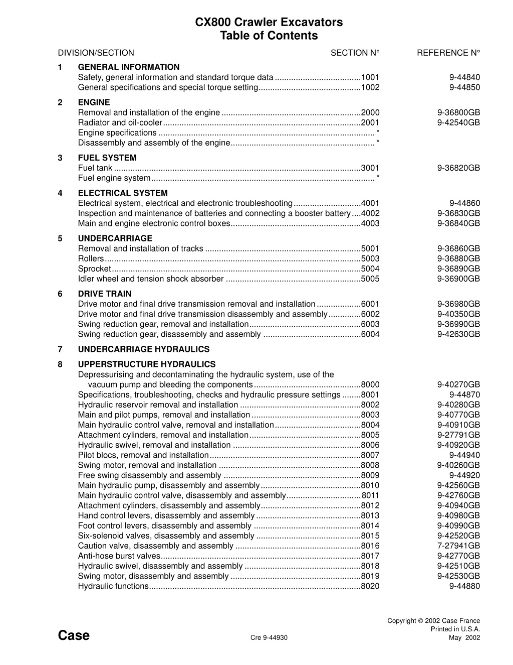
CX800 Crawler Excavators Table of Contents SECTION N REFERENCE N DIVISION/SECTION 1 GENERAL INFORMATION Safety, general information and standard torque data.....................................1001 General specifications and special torque setting............................................1002 9-44840 9-44850 2 ENGINE Removal and installation of the engine............................................................2000 Radiator and oil-cooler.....................................................................................2001 Engine specifications .............................................................................................* Disassembly and assembly of the engine..............................................................* 9-36800GB 9-42540GB 3 FUEL SYSTEM Fuel tank..........................................................................................................3001 Fuel engine system................................................................................................* 9-36820GB 4 ELECTRICAL SYSTEM Electrical system, electrical and electronic troubleshooting.............................4001 Inspection and maintenance of batteries and connecting a booster battery....4002 Main and engine electronic control boxes........................................................4003 9-44860 9-36830GB 9-36840GB 5 UNDERCARRIAGE Removal and installation of tracks ...................................................................5001 Rollers..............................................................................................................5003 Sprocket...........................................................................................................5004 Idler wheel and tension shock absorber ..........................................................5005 9-36860GB 9-36880GB 9-36890GB 9-36900GB 6 DRIVE TRAIN Drive motor and final drive transmission removal and installation...................6001 Drive motor and final drive transmission disassembly and assembly..............6002 Swing reduction gear, removal and installation................................................6003 Swing reduction gear, disassembly and assembly ..........................................6004 9-36980GB 9-40350GB 9-36990GB 9-42630GB 7 UNDERCARRIAGE HYDRAULICS 8 UPPERSTRUCTURE HYDRAULICS Depressurising and decontaminating the hydraulic system, use of the vacuum pump and bleeding the components..............................................8000 Specifications, troubleshooting, checks and hydraulic pressure settings ........8001 Hydraulic reservoir removal and installation ....................................................8002 Main and pilot pumps, removal and installation...............................................8003 Main hydraulic control valve, removal and installation.....................................8004 Attachment cylinders, removal and installation................................................8005 Hydraulic swivel, removal and installation .......................................................8006 Pilot blocs, removal and installation.................................................................8007 Swing motor, removal and installation .............................................................8008 Free swing disassembly and assembly ...........................................................8009 Main hydraulic pump, disassembly and assembly...........................................8010 Main hydraulic control valve, disassembly and assembly................................8011 Attachment cylinders, disassembly and assembly...........................................8012 Hand control levers, disassembly and assembly.............................................8013 Foot control levers, disassembly and assembly ..............................................8014 Six-solenoid valves, disassembly and assembly .............................................8015 Caution valve, disassembly and assembly ......................................................8016 Anti-hose burst valves......................................................................................8017 Hydraulic swivel, disassembly and assembly..................................................8018 Swing motor, disassembly and assembly........................................................8019 Hydraulic functions...........................................................................................8020 9-40270GB 9-44870 9-40280GB 9-40770GB 9-40910GB 9-27791GB 9-40920GB 9-44940 9-40260GB 9-44920 9-42560GB 9-42760GB 9-40940GB 9-40980GB 9-40990GB 9-42520GB 7-27941GB 9-42770GB 9-42510GB 9-42530GB 9-44880 Copyright 2002 Case France Printed in U.S.A. Case Cre 9-44930 May 2002
DIVISION/SECTION SECTION N REFERENCE N 9 UPPERSTRUCTURE Upperstructure, turntable bearing and counterweight......................................9002 Boom, dipper and bucket.................................................................................9003 Seat and seat belt............................................................................................9004 Cab and cab equipment...................................................................................9005 Air conditioning troubleshooting.......................................................................9006 Air conditioning unit disassembly and assembly..............................................9007 Air conditioning servicing .................................................................................9008 Air conditioning components............................................................................9009 Removal and installation attachment, counterweight and side fram................9010 Attachment reinforcement procedures.............................................................9012 Large format hydraulic and electrical schematics.........................................Pocket 9-42550GB 9-42620GB 9-40960GB 9-40970GB 7-xxxxxFR 7-29910GB 7-xxxxxFR 7-xxxxxFR 9-44890 9-43940 9-42650 * Consult the Engine Service Manual Sections to be distributed at a later date NOTE: Case Company reserves the right to make changes in the speci- fication and design of the machine without prior notice and without incur- ring any obligation to modify units previously sold. The description of the models shown in this manual has been made in accordance with the technical specifications known as of the date of design of this document. Cre 9-44930 Edition 05-02
1001 Section 1001 SAFETY, GENERAL INFORMATION AND STANDARD TORQUE DATA Copyright 2002 Case France Printed in U.S.A. Case Cre 9-44840 May 2002
https://www.ebooklibonline.com Hello dear friend! Thank you very much for reading. Enter the link into your browser. The full manual is available for immediate download. https://www.ebooklibonline.com
1001-2 TABLE OF CONTENTS GENERAL INFORMATION.......................................................................................................................................3 SAFETY.....................................................................................................................................................................4 STANDARD TORQUE DATA FOR CAP SCREWS AND NUTS...............................................................................6 Cre 9-44840 Issued 05-02
1001-3 GENERAL INFORMATION Gears Cleaning Clean all metal parts except bearings, in a suitable cleaning solvent or by steam cleaning. Do not use caustic soda for steam cleaning. After cleaning, dry and put oil on all parts. Clean oil passages with compressed air. Clean bearings in a suitable cleaning solvent. Dry the bearings completely and put oil on the bearings. Check all gears for wear and damage. Replace gears that have wear or damage. Oil Seals, O-rings and Gaskets Always install new oil seals, O-rings and gaskets. Put petroleum jelly on seals and O-rings. Shafts Inspection Check all shafts that have wear or damage. Check the bearing and oil seal surfaces of the shafts for damage. Check all parts when the parts are disassembled. Replace all parts that have wear or damage. Small scoring or grooves can be removed with a hone or crocus cloth. Complete a visual inspection for indications of wear, pitting and the replacement of parts necessary to prevent early failures. Service Parts Always install genuine Case service parts. When ordering refer to the Parts Catalog for the correct part number of the genuine Case replacement items. Failures due to the use of other than genuine Case replacement parts are not covered by warranty. Bearings Check bearings for easy action. If bearings have a loose fit or rough action, replace the bearing. Wash bearings with a suitable cleaning solvent and permit to air dry. DO NOT DRY BEARINGS WITH COMPRESSED AIR. Lubrication Only use the oils and lubricants specified in the Operator s or Service Manuals. Failures due to the use of non-specified oils and lubricants are not covered by warranty. Needle Bearings Before you press needle bearings in a bore always remove any metal protrusions in the bore or edge of the bore. Before you press bearings into position, put petroleum jelly on the inside and outside diameter of the bearings. Cre 9-44840 Issued 05-02
1001-4 SAFETY This symbol means ATTENTION! BECOME ALERT! YOUR SAFETY IS INVOLVED. The message that follows the symbol contains important information about safety. Carefully read the message. Make sure you fully understand the causes of possible injury or death. ! To prevent injury always follow the Warning, Caution and Danger notes in this section and throughout the manual. WARNING: Before starting engine, study Operator s Manual safety messages. Read all safety signs on machine. Clear the area of other persons. Learn and practice safe use of controls before operating. It is your responsibility to understand and follow manufacturers instructions on machine operation, service and to observe pertinent laws and regulations. Operator s and Service Manuals may be obtained from your Case dealer. Place a Do not operate tag on the starter switch key before carrying out any service or repair work on the machine. ! . WARNING: Read the operator s manual to familiarize yourself with the correct control functions. ! WARNING: Operate the machine and equipment controls from the seat position only. Any other method could result in serious injury. WARNING: If you wear clothing that is too loose or do not use the correct safety equipment for your job, you can be injured. Always wear clothing that will not catch on objects. Extra safety equipment that can be required includes hard hat, safety shoes, ear protection, eye or face protection, heavy gloves and reflector clothing. ! ! WARNING: This is a one man machine, no riders allowed. ! WARNING: When working in the area of the fan belt with the engine running, avoid loose clothing if possible, and use extreme caution. ! WARNING: When doing checks and tests on the equipment hydraulics, follow the procedures as they are written. DO NOT change the procedure. ! WARNING: When putting the hydraulic cylinders on this machine through the necessary cycles to check operation or to remove air from a circuit, make sure all people are out of the way. ! Cre 9-44840 Issued 05-02
1001-5 WARNING: When servicing or repairing the machine, keep the shop floor and operator s compartment and steps free of oil, water, grease, tools, etc. Use an oil absorbing material and/or shop cloths as required. Use safe practices at all times. WARNING: Use insulated gloves or mittens when working with hot parts. ! ! WARNING: Lower all attachments to the ground or use stands to safely support the attachments before you do any maintenance or service. ! WARNING: Some components of this machine are very heavy. Use suitable lifting equipment or additional help as instructed in this Service Manual. ! WARNING: Pin sized and smaller streams of hydraulic oil under pressure can penetrate the skin and result in serious infection. If hydraulic oil under pressure does penetrate the skin, seek medical treatment immediately. Maintain all hoses and tubes in good condition. Make sure all connections are tight. Make a replacement of any tube or hose that is damaged or thought to be damaged. DO NOT use your hand to check for leaks, use a piece of cardboard or wood. WARNING: Engine exhaust fumes can cause death. If it is necessary to start the engine in a closed place, remove the exhaust fumes from the area with an exhaust pipe extension. Open the doors and get outside air into the area. ! ! WARNING: When the battery electrolyte is frozen, the battery can explode if (1), you try to charge the battery, or (2), you try to jump start and run the engine. To prevent the battery electrolyte from freezing, try to keep the battery at full charge. If you do not follow these instructions, you or others in the area can be injured. WARNING: When removing hardened pins such as a pivot pin, or a hardened shaft, use a soft head (brass or bronze) hammer or use a driver made from brass or bronze and a steel head hammer. ! ! WARNING: When using a hammer to remove and install pivot pins or separate parts using compressed air or using a grinder, wear eye protection that completely encloses the eyes (approved goggles or other approved eye protectors). ! WARNING: Use suitable floor (service) jacks or chain hoist to raise wheels or tracks off the floor. Always block machine in place with suitable safety stands. ! Cre 9-44840 Issued 05-02
1001-6 STANDARD TORQUE DATA FOR CAP SCREWS AND NUTS Tightening of Cap Screws and Nuts Tighten alternately so that tightening torque can be applied evenly. The numbers in the figure below indicate the order of tightening. JS00481B Cap screws which have had Loctite used (white residue remains after removal) should be cleaned with light oil or suitable cleaning solvent and dried. Apply 2-3 drops of Loctite to the thread portion of the cap screw and then tighten. Torque Table Tighten cap screws and nuts according to the table below if there are no other special instructions. Cap Screw Name Size (Size) M6 M8 M10 M12 M14 M16 M18 M20 [in.] 0.39 0.51 0.67 0.75 0.87 0.95 1.06 1.18 Spanner [mm] 10 13 17 19 22 24 27 30 Cap Screw [lb-ft] 5.1 11.6 23.9 43.4 72.5 116.0 144.6 202.4 Tightening torque [Nm] 6.9 15.7 32.5 58.8 98.1 157.2 196.0 274.0 [in.] 0.20 0.24 0.32 0.39 0.47 0.55 0.55 0.67 Spanner Socket Head Cap Screw [mm] 5 6 8 10 12 14 14 17 [lb-ft] 6.5 15.9 31.1 57.8 86.8 130.1 180.8 253.1 Tightening torque [Nm] 8.8 21.6 42.1 78.4 117.6 176.4 245.0 343.0 Cre 9-44840 Issued 05-02
Section 1002 1002 SPECIFICATIONS AND SPECIAL TORQUE SETTINGS Copyright 2002 Case France Printed in U.S.A. Case Cre 9-44850 May 2002
1002-2 TABLE OF CONTENTS TYPE, SERIAL NUMBER AND YEAR OF MANUFACTURE OF THE MACHINE....................................................3 Machine.................................................................................................................................................................3 Engine...................................................................................................................................................................3 Serial numbers of the components .......................................................................................................................3 INGREDIENTS..........................................................................................................................................................4 Hydraulic fluid chart ..............................................................................................................................................4 Transmission assembly oil ...................................................................................................................................4 Greases ................................................................................................................................................................4 Engine oil ..............................................................................................................................................................5 Viscosity of oils/Operating range of oils ................................................................................................................5 Fuel ......................................................................................................................................................................6 Antifreeze/anticorrosive ........................................................................................................................................6 Environment .........................................................................................................................................................6 Plastic and resin parts ..........................................................................................................................................6 SPECIFICATIONS.....................................................................................................................................................7 Engine...................................................................................................................................................................7 Capacities .............................................................................................................................................................7 Electrical system ...................................................................................................................................................7 Hydraulic system...................................................................................................................................................8 Cylinder.................................................................................................................................................................8 Control valve .........................................................................................................................................................9 Swing ....................................................................................................................................................................9 Travel....................................................................................................................................................................9 Undercarriage .......................................................................................................................................................9 Attachment..........................................................................................................................................................10 Weight of components ........................................................................................................................................10 DIMENSIONS AND WEAR LIMIT OF THE TRACK-LAYER ASSEMBLY ..............................................................11 Sprocket..............................................................................................................................................................11 Idler wheel...........................................................................................................................................................12 Upper roller .........................................................................................................................................................13 Lower roller .........................................................................................................................................................14 Track ...................................................................................................................................................................15 DIMENSIONS AND WEAR LIMITS OF ATTACHMENT MOBILE JOINTS.............................................................16 1. Boom foot/Frame ............................................................................................................................................16 2. Boom cylinder foot/Frame...............................................................................................................................17 3. Boom cylinder head/Boom..............................................................................................................................17 4. Dipper cylinder foot/Boom...............................................................................................................................18 5. Boom/Dipper ...................................................................................................................................................18 6. Dipper cylinder head/Dipper............................................................................................................................18 7. Bucket cylinder foot/Dipper .............................................................................................................................19 8. Connecting rod/Dipper ....................................................................................................................................19 9. Compensator/Bucket.......................................................................................................................................19 10. Connecting rod/Compensator/Bucket cylinder head.....................................................................................20 11. Dipper/Bucket................................................................................................................................................20 SPECIAL TORQUE SETTINGS..............................................................................................................................21 MACHINE OVERALL DIMENSIONS.......................................................................................................................24 WARNING: This symbol is used in this manual to indicate important safety messages. Whenever you see this symbol, carefully read the message which follows. Your safety depends on it. ! Cre 9-44850 Issued 05-02
1002-3 TYPE, SERIAL NUMBER AND YEAR OF MANUFACTURE OF THE MACHINE For all part orders, request for information or assistance, always specify the type and the serial number of the machine to your Case dealer. Fill in the following lines with the required information: Type, serial number, year of manufacture of the machine and the serial numbers of the hydraulic and mechanical components. Machine 1 3 2 CS00M518 CP98N006 (1) Type............................................................................. (2) Serial number.............................................................. (3) Year of manufacture.................................................... Engine Make and type............................................................................................................................................................. Serial number.............................................................................................................................................................. Serial numbers of the components Hydraulic pump............................................................................................................................................................ Swing reduction gear................................................................................................................................................... Travel reduction gears................................................................................................................................................. Travel control valve...................................................................................................................................................... Attachment control valve ............................................................................................................................................. Swing control valve...................................................................................................................................................... Cre 9-44850 Issued 05-02
1002-4 INGREDIENTS The ingredients must correspond to specific characteristics for every usage. WARNING: You must respect the operating conditions for the different ingredients. ! Hydraulic fluid chart NOTE: Use only hydraulic oils meeting Case specifications or equivalent AW (anti-wear) hydraulic oils. TEMPERATURE FAHRENHEIT TEMPERATURE CELSIUS CS02K507 NOTE: Case specification MS1209 Fluid is used in place of ISO VG 32 (-5 to + 65 F) and ISO VG 46 (+10 to + 90 F). NOTE: Case specifications MS1230 Grade NT or Grade LT is used in place of ISO VG 32 (-5 to + 65 F), ISO VG 46 (+10 to + 90 F), ISO VG 100 (+30 to +115 F) and MS1210 TCH Transmission assembly oil Extreme assemblies in housing. Extreme pressure oil TYPE API GL5 GRADE 80W90 and ISO VG 150 pressure oil used for transmission Greases The type of grease to be used depends on the ambient temperature. Hot and temperate climates -4 F to + 140 F (-20 C to +60 C) Extreme pressure EP NLGI grade 2 grease with molybdenum disulfide. Cold climates -40 F to +68 F (-40 C to +20 C) Extreme pressure EP NLGI grade 0 grease. Cre 9-44850 Issued 05-02
1002-5 Engine Oil THE CASE No. 1 engine oil is recommended for your engine. This oil ensures proper lubrication of your engine for all operating conditions. If you are unable to procure the CASE No. 1 Multiperformance or Performance engine oil, use the corresponding oil from the API/CG/CF category. NOTE: Do not put any Performance Additives or any other additives in the engine housing .The oil changing intervals are indicated in this manual based on tests carried out on CASE lubricants. RD97F136 RD97F100 Viscosity of oils/Operating range of oils A 3 1 2 4 B CS98M561 (A) FAHRENHEIT TEMPERATURE (B) CELSIUS TEMPERATURE (1) ALL-SEASONS (*) SHOWS THAT AN ENGINE OIL HEATER OR ENGINE COOLANT SOLUTION HEATER MUST BE USED. (2) WINTER (3) TROPICAL (4) ARCTIC Cre 9-44850 Issued 05-02
1002-6 Fuel Environment The fuel to be used must comply with the D975 norm of the American Society for Testing and Materials (ASTM). Before carrying out any maintenance operation on this machine and before throwing away the liquids or lubricants used, always think of the environment. Never throw oil or liquids on the ground and never put them in leaking containers. Use type N 2 fuel, use of other fuels can cause a loss of engine power and excessive fuel consumption. Consult your local centre for ecological recycling for information on the appropriate method for disposing off these substances. In cold weather, it is provisionally accepted that a mixture of N 1 et N 2 fuels be used. Contact your fuel supplier. Plastic and resin parts If the temperature drops below the freezing point of the fuel (point where paraffin appears), paraffin crys- tals in the fuel will cause loss of engine power or starting trouble. When cleaning plastic parts, the console, the instru- ment panel, the indicators etc... avoid using petrol, kerosene, paint solvents etc... Use only water, soap and a soft cloth. IMPORTANT: In cold weather, fill up the reservoir with fuel after each workday, in order to avoid the for- mation of condensation. Storing fuel The use of petrol, kerosene, paint solvents etc... causes discoloration, cracks or deformation of these parts. Prolonged storage of fuel promotes the accumulation of foreign bodies or condensed moisture in the stor- age tank. Many engine failures are caused by the presence of water in fuel. The storage tank must be placed outside and the fuel should be maintained at as low a temperature as possible. Drain the condensed moisture at regular intervals. Antifreeze/anticorrosive Use the antifreeze in all seasons to protect the cool- ant system from corrosion and to avoid any risk of freezing. In environments with a temperature greater than - 33 F (-36 C), use a 50% mixture of antifreeze in an ethylene glycol base. In environments with a temperature less than -33 F (- 36 C), it is recommended that you use a 40% water and 60% antifreeze mixture. Cre 9-44850 Issued 05-02
1002-7 SPECIFICATIONS Engine Make................................................................................................................................................................... Isuzu Model...................................................................................................................................................BB-6WG1XQB Type: Four stroke, water cooled with overhead valves, direct injection in-line cylinder (electrical control) with turbo- charger. Number of cylinders...................................................................................................................................................6 Bore and stroke ..............................................................................................................................................5.7x6 in Displacement................................................................................................................................................ 957 cu in Operating conditions Idle..................................................................................................................................................................900 rpm Max speed....................................................................................................................................................1870 rpm SAE net horse power.......................................................................................................................................450 HP Max torque................................................................................................................................1410 lb ft to 1500 rpm Capacities Engine oil capacity..........................................................................................................................................12.4 gal Engine cooling circuit......................................................................................................................................26.4 gal Capacity of only the radiator ............................................................................................................................9.5 gal Fuel reservoir................................................................................................................................................237.7 gal Hydraulic fluid reservoir capacity....................................................................................................................81.8 gal Total hydraulic circuit capacity......................................................................................................................190.2 gal Capacity of only the oil-cooler ........................................................................................................................15.8 gal Travel reduction gear housing capacity............................................................................................................3.5 gal Swing drive housing capacity...........................................................................................................................3.5 gal NOTE: These capacities are given only for information purposes. To check the fluid levels, always use the oil gauge, visual gauges or the filler cap. Electrical system Type of system ........................................................................................................................24 volts earth negative Alternator amperage.................................................................................................................................90 amperes Battery Number of batteries required ................................................................................................................................2 Voltage of each battery .............................................................................................................................. 12 volts Capacity ...................................................................................................................................................... 200 Ah Backup ......................................................................................................................................................... xx min Starter Voltage ....................................................................................................................................................... 24 volts Power..............................................................................................................................................................7 kW Voltage regulator .............................................................................................................. built-in, without adjustment Cre 9-44850 Issued 05-02
1002-8 Hydraulic system Main hydraulic pump Variable flow double pump, with axial pistons. Max flow .................................................................................................................................................2x135.7 gpm Displacement........................................................................................................................................... 2x16.9 cu in Hydraulic pilot pump Fixed flow pump Max flow .........................................................................................................................................................7.1 gpm Displacement................................................................................................................................................. 0.9 cu in Pressure setting Pilot circuit main relief...................................................................................................................................... 638 psi Main relief (standard)..................................................................................................................................... 4554 psi Main relief (boost).......................................................................................................................................... 4974 psi Secondary relief (boom, dipper and bucket).................................................................................................. 5264 psi Secondary relief (swing)................................................................................................................................ 4046 psi Secondary relief (travel) ................................................................................................................................ 4975 psi Safety valve (boom and dipper)..................................................................................................................... 5265 psi Cylinder Boom cylinder Cylinder bore....................................................................................................................................................7.87 in Rod diameter......................................................................................................................................................5.5 in Stroke...............................................................................................................................................................74.5 in Dipper cylinder Cylinder bore....................................................................................................................................................8.46 in Rod diameter......................................................................................................................................................5.9 in Stroke...............................................................................................................................................................90.1 in Bucket cylinder Cylinder bore......................................................................................................................................................7.4 in Rod diameter......................................................................................................................................................5.1 in Stroke..................................................................................................................................................................61 in Cre 9-44850 Issued 05-02
1002-9 Control valve Five-element control valve for dipper, boom acceleration, swing, option and right travel. Four-element control valve for dipper acceleration, bucket, boom and left travel. Load holding relief valve for boom and dipper. Swing Fixed flow engine with axial pistons. Automatic disk brakes. Upperstructure frame swing speed..................................................................................................................7.6 rpm Swing torque.................................................................................................................................................55845 lbf Tail swing.......................................................................................................................................................13 ft 4 in Displacement............................................................................................................................................... 12.8 cu in Work load ........................................................................................................................................................66 gpm Braking torque ................................................................................................................................... 856 to 1109lb ft Minimum brake release pressure .................................................................................................................... 333 psi Permissible motor leakage ...........................................................................................................................1.32 gpm Travel Two-speed motor with axial pistons. Automatic disk brakes. Low speed ......................................................................................................................................................1.8 mph High speed .....................................................................................................................................................2.7 mph Surmountable ramp.....................................................................................................................................70% (35 ) Tractive effort..............................................................................................................................................122390 lbf Displacement....................................................................................................................................... 20.5/13.9 cu in Work load ......................................................................................................................................................132 gpm Reduction ratio .................................................................................................................................................91.974 Braking torque (reduction gear excluded) ......................................................................................................680 lb ft Permissible motor leakage ...........................................................................................................................3.43 gpm Undercarriage Monobloc frame with fabricated elements. Lubricated rollers and idler wheels. Grease track tension. Ground pressure with 29.5 in track pads .................................................................................................................................. 14 psi Cre 9-44850 Issued 05-02
1002-10 Attachment Digging force ................................................................................................................................................84218 lbf Thrust force 9 ft 9 in dipper...............................................................................................................................................74760 lbf 12 ft 0 in dipper.............................................................................................................................................64852 lbf 14 ft 7 in dipper.............................................................................................................................................55620 lbf 18 ft 5 in dipper.............................................................................................................................................47062 lbf Weight of components Engine ........................................................................................................................................................... 2756 lbs Hydraulic pump................................................................................................................................................ 661 lbs Attachment control valve................................................................................................................................. 948 lbs Swing motor and reduction gear assembly ................................................................................................... 1810 lbs Travel motor and reduction gear assembly ................................................................................................... 2866 lbs Boom cylinder................................................................................................................................................ 1576 lbs Dipper cylinder............................................................................................................................................... 2260 lbs Bucket cylinder.............................................................................................................................................. 1323 lbs Counterweight ............................................................................................................................................. 27558 lbs Cab.................................................................................................................................................................. 560 lbs Turntable ....................................................................................................................................................... 2954 lbs Upperstructure assembly..............................................................................................................................52911 lbs Hydraulic swivel............................................................................................................................................... 225 lbs Frame assembly.......................................................................................................................................... 28880 lbs Machine without attachment...................................................................................................................... 140667 lbs Attachment .................................................................................................................................................. 33201 lbs Boom assembly........................................................................................................................................... 17196 lbs Dipper assembly............................................................................................................................................ 9480 lbs Radiator and oil-cooler assembly...................................................................................................................1146 lbs Fuel reservoir................................................................................................................................................. 1029 lbs Hydraulic reservoir........................................................................................................................................... 932 lbs Idler wheel..................................................................................................................................................... 1471 lbs Upper roller...................................................................................................................................................... 166 lbs Lower roller...................................................................................................................................................... 397 lbs Tension damper............................................................................................................................................. 1517 lbs 29.5 in track (25)............................................................................................................................................ 5015 lbs 35.4 in track (25)............................................................................................................................................ 5697 lbs 43.3 in track (25)............................................................................................................................................ 6554 lbs Cre 9-44850 Issued 05-02
1002-11 DIMENSIONS AND WEAR LIMIT OF THE TRACK-LAYER ASSEMBLY Sprocket Dimensions a P d b c CS01B512 Mark Dimension (in) Standard Limit Standard Limit Standard Limit Standard Limit Standard Limit a b 38.5 c 38 d 10.24 P Gauge 10.24 in 15 39 7.8" 0.19 in 0.19 in 64 R0.23 in R0.23 in R1.68 in R1.68 in 38.5 in 38 in CI01M506 Cre 9-44850 Issued 05-02
1002-12 Idler wheel Dimensions Dimension (in) 32.6 Mark Standard Limit Standard Limit Standard Limit Standard Limit Standard Limit Standard Limit Standard Limit a 0.88 b b 4.9 c c d (shaft) d (ring) a e f e f d CS01B514 Gauge 0.88 in R0.15 in R0.15 in 15 4.9 in 10.4 in CI01M507 Cre 9-44850 Issued 05-02
1002-13 Upper roller Dimensions Dimension (in) 8.58 Mark g e Standard Limit Standard Limit Standard Limit Standard Limit Standard Limit Standard Limit Standard Limit Standard Limit a 0.62 b 4.9 c d (shaft) a d d (ring) e b f f c g CS01B516 Gauge R0.11 0.62 in R0.11 10 4.9 in 10.6 in CI01M508 Cre 9-44850 Issued 05-02
1002-14 Lower roller Dimensions d f g e a b CS01B518 Dimension (in) 10.6 Dimension (in) Mark Mark Standard Limit Standard Limit Standard Limit Standard Limit Standard Limit Standard Limit Standard Limit e (ring) a 0.98 b f 10.7 d g e (shaft) Gauge 4.9 in R0.11R0.11 0.98 in 17 10.7 in 13.5 in CI01M509 Cre 9-44850 Issued 05-02
1002-15 Track c d e e f f g g h h b a CS01B520 Dimension (in) Dimension (in) Mark Mark Standard Limit Standard Limit Standard Limit Standard Limit Standard Limit Standard Limit Standard Limit Standard Limit e (ring) a b f (ring) c g (shaft) d h Cre 9-44850 Issued 05-02
Suggest: If the above button click is invalid. Please download this document first, and then click the above link to download the complete manual. Thank you so much for reading
1002-16 DIMENSIONS AND WEAR LIMITS OF ATTACHMENT MOBILE JOINTS 4 3 1 5 6 9 2 11 7 8 10 CS01B521 1. Boom foot/Frame a c b d CS01B522 Dimension (in) 43.7 Mark Standard Limit Standard Limit Standard Limit Standard Limit Standard Limit a 43.6 b 0.04 c (a - b) 5.9 d (shaft) d (ring) Cre 9-44850 Issued 05-02
https://www.ebooklibonline.com Hello dear friend! Thank you very much for reading. Enter the link into your browser. The full manual is available for immediate download. https://www.ebooklibonline.com


![Comprehensive Case Study on [Insert Case Title Here]](/thumb/159705/comprehensive-case-study-on-insert-case-title-here.jpg)


![Property Settlements in Family Law: Case Study of Stamatou & Stamatou [2022] FedCFamC1F 241](/thumb/63303/property-settlements-in-family-law-case-study-of-stamatou-stamatou-2022-fedcfamc1f-241.jpg)