CASE CX700B CRAWLER EXCAVATOR Service Repair Manual Instant Download
Please open the website below to get the complete manualnn//

Download Presentation

Please find below an Image/Link to download the presentation.
The content on the website is provided AS IS for your information and personal use only. It may not be sold, licensed, or shared on other websites without obtaining consent from the author. Download presentation by click this link. If you encounter any issues during the download, it is possible that the publisher has removed the file from their server.
E N D
Presentation Transcript
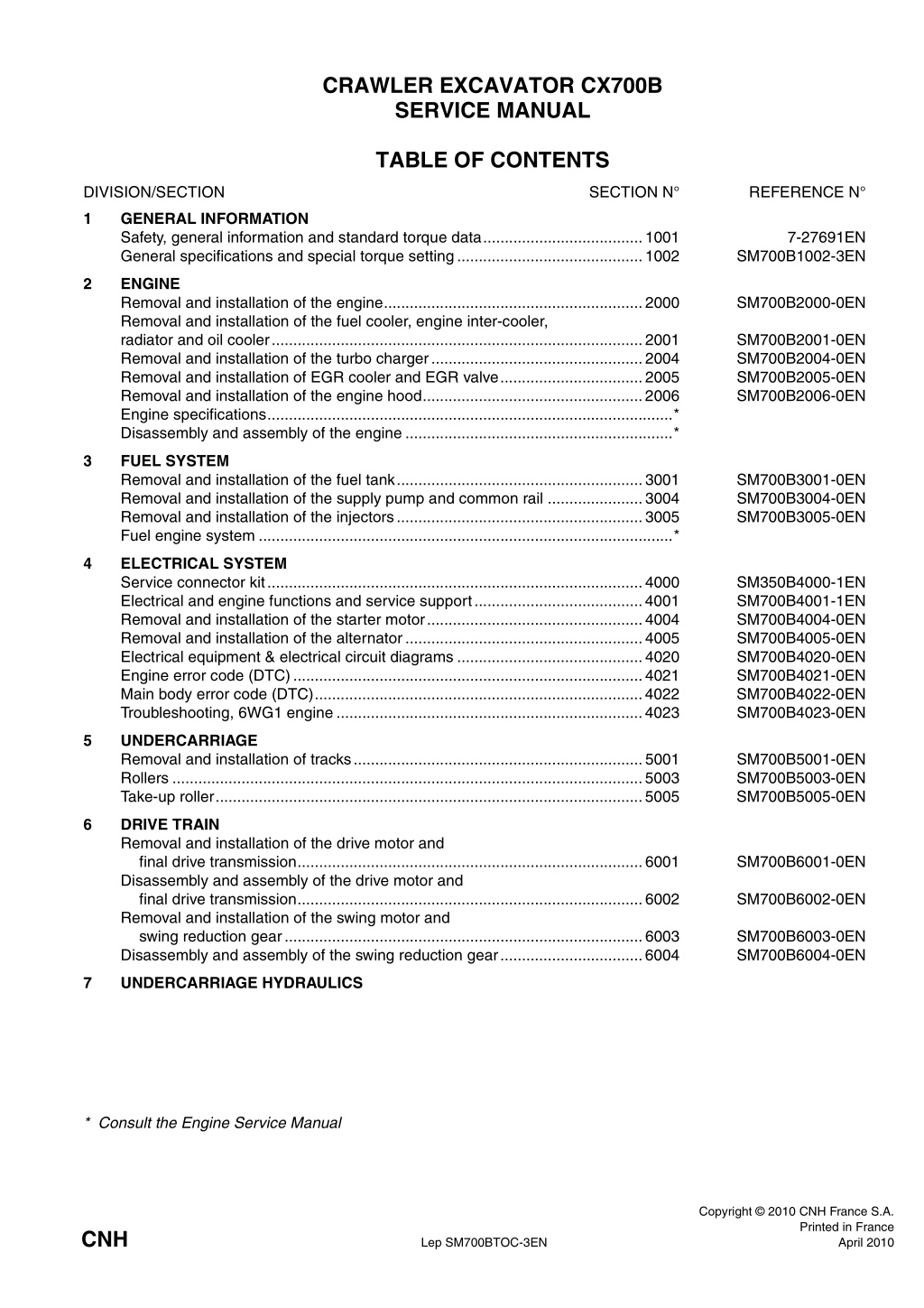
CRAWLER EXCAVATOR CX700B SERVICE MANUAL TABLE OF CONTENTS DIVISION/SECTION SECTION N REFERENCE N 1 GENERAL INFORMATION Safety, general information and standard torque data.....................................1001 General specifications and special torque setting...........................................1002 7-27691EN SM700B1002-3EN 2 ENGINE Removal and installation of the engine............................................................2000 Removal and installation of the fuel cooler, engine inter-cooler, radiator and oil cooler......................................................................................2001 Removal and installation of the turbo charger.................................................2004 Removal and installation of EGR cooler and EGR valve.................................2005 Removal and installation of the engine hood...................................................2006 Engine specifications..............................................................................................* Disassembly and assembly of the engine ..............................................................* SM700B2000-0EN SM700B2001-0EN SM700B2004-0EN SM700B2005-0EN SM700B2006-0EN 3 FUEL SYSTEM Removal and installation of the fuel tank.........................................................3001 Removal and installation of the supply pump and common rail ......................3004 Removal and installation of the injectors.........................................................3005 Fuel engine system ................................................................................................* SM700B3001-0EN SM700B3004-0EN SM700B3005-0EN 4 ELECTRICAL SYSTEM Service connector kit.......................................................................................4000 Electrical and engine functions and service support.......................................4001 Removal and installation of the starter motor..................................................4004 Removal and installation of the alternator.......................................................4005 Electrical equipment & electrical circuit diagrams ...........................................4020 Engine error code (DTC).................................................................................4021 Main body error code (DTC)............................................................................4022 Troubleshooting, 6WG1 engine.......................................................................4023 SM350B4000-1EN SM700B4001-1EN SM700B4004-0EN SM700B4005-0EN SM700B4020-0EN SM700B4021-0EN SM700B4022-0EN SM700B4023-0EN 5 UNDERCARRIAGE Removal and installation of tracks...................................................................5001 Rollers .............................................................................................................5003 Take-up roller...................................................................................................5005 SM700B5001-0EN SM700B5003-0EN SM700B5005-0EN 6 DRIVE TRAIN Removal and installation of the drive motor and final drive transmission................................................................................6001 Disassembly and assembly of the drive motor and final drive transmission................................................................................6002 Removal and installation of the swing motor and swing reduction gear...................................................................................6003 Disassembly and assembly of the swing reduction gear.................................6004 SM700B6001-0EN SM700B6002-0EN SM700B6003-0EN SM700B6004-0EN 7 UNDERCARRIAGE HYDRAULICS * Consult the Engine Service Manual Copyright 2010 CNH France S.A. Printed in France April 2010 CNH Lep SM700BTOC-3EN
DIVISION/SECTION SECTION N REFERENCE N 8 UPPERSTRUCTURE HYDRAULICS Specifications, troubleshooting, checks and hydraulic pressure settings..........................................................................8001 Removal and installation of the hydraulic reservoir .........................................8002 Removal and installation of the main hydraulic pump......................................8003 Removal and installation of the main hydraulic control valve...........................8004 Removal and installation of the attachment cylinders......................................8005 Removal and installation of the hydraulic swivel..............................................8006 Removal and installation of the pilot blocs.......................................................8007 Disassembly and assembly of the main hydraulic pump .................................8010 Disassembly and assembly of the main hydraulic control valve ......................8011 Disassembly and assembly of the attachment cylinders .................................8012 Disassembly and assembly of the hand control levers....................................8013 Disassembly and assembly of the foot control levers ......................................8014 Disassembly and assembly of the cushion valve.............................................8016 Removal and installation of the safety valve....................................................8017 Disassembly and assembly of the swing motor...............................................8019 Hydraulic functions ..........................................................................................8020 Hydraulic component functions........................................................................8030 SM700B8001-0EN SM700B8002-0EN SM700B8003-0EN SM700B8004-0EN SM700B8005-0EN SM700B8006-0EN SM700B8007-0EN SM700B8010-0EN SM700B8011-0EN SM700B8012-0EN SM130B8013-0EN SM350B8014-0EN SM130B8016-0EN SM700B8017-0EN SM700B8019-0EN SM700B8020-0EN SM700B8030-1EN 9 UPPERSTRUCTURE Removal and installation of the counterweight ................................................9002 Removal and installation of the boom, dipper and bucket ...............................9003 Removal and installation of the seat................................................................9004 Removal and installation of the cab and cab equipment .................................9005 Air conditioner functions and troubleshooting..................................................9006 Air conditioning unit .........................................................................................9007 Air conditioning components............................................................................9009 Removal and installation of the attachment, counterweight and side frame.............................................................................................9010 Large size hydraulic schematics...................................................................Pocket Large size electrical schematics...................................................................Pocket SM700B9002-0EN SM700B9003-0EN SM130B9004-0EN SM130B9005-0EN SM700B9006-1EN SM700B9007-0EN SM700B9009-0EN SM700B9010-0EN KWJ11230-E02 KWR10070-E04 NOTE: CNH France S.A. Company reserves the right to make changes in the specification and design of the machine without prior notice and without incurring any obligation to modify units previously sold. The description of the models shown in this manual has been made in accordance with the technical speci- fications known as of the date of design of this document. All data given in this manual is subject to production variations. Dimensions and weights are provided with approximate values and the machine fitting shown in the illustrations may not correspond with standard models. For precise information on specific machine models and versions, please contact your CASE dealer. Reproduction or tranlation, even partial, is prohibited without written authorization from CNH France SA Company. Lep SM700BTOC-3EN Issued 04-2010
1001 Section 1001 SAFETY, GENERAL INFORMATION AND TORQUE SPECIFICATIONS Copyright 2006 CNH France S.A. Printed in France February 2006 CNH Lep 7-27691EN
https://www.ebooklibonline.com Hello dear friend! Thank you very much for reading. Enter the link into your browser. The full manual is available for immediate download. https://www.ebooklibonline.com
1001-3 GENERAL INFORMATION Cleanning Gears Clean all metal parts except bearings, in a suitable cleaning solvent or by steam cleaning. Do not use caustic soda for steam cleaning. After cleaning, dry and put oil on all parts. Clean oil passages with compressed air. Clean bearings in a suitable cleaning solvent, dry the bearings completely and put oil on the bearings. Inspection Check all gears for wear and damage. Replace gears that have wear or damage. Oil seals, O-rings and gaskets Always install new oil seals, O-rings and gaskets. Put petroleum jelly on seals and O-rings. Shafts Check all shafts that have wear or damage. Check the bearing and oil seal surfaces of the shafts for damage. Service parts Check all parts when the parts are disassembled. Replace all parts that have wear or damage. Small scoring or grooves can be removed with a hone or crocus cloth. Complete a visual inspection for indications of wear, pitting and the replacement of parts necessary to prevent early failures. Bearings Always install genuine Case service parts. When ordering refer to the Parts Catalog for the correct part number of the genuine Case replacement items. Failures due to the use of other than genuine Case replacement parts are not covered by warranty. Lubrication Check bearings for easy action. If bearings have a loose fit or rough action replace the bearing. Wash bearings with a suitable cleaning solvent and permit to air dry. DO NOT DRY BEARINGS WITH COMPRESSED AIR. Needle bearings Only use the oils and lubricants specified in the Operator s or Service Manuals. Failures due to the use of non-specified oils and lubricants are not covered by warranty. Before you press needle bearings in a bore always remove any metal protrusions in the bore or edge of the bore. Before you press bearings into position put petroleum jelly on the inside and outside diameter of the bearings. Lep 7-27691EN Issued 02-06
1001-4 SAFETY This symbol means ATTENTION! BECOME ALERT! YOUR SAFETY IS INVOLVED. The message that follows the symbol contains important information about safety. Carefully read the message. Make sure you fully understand the causes of possible injury or death. ! To prevent injury always follow the Warning, Caution and Danger notes in this section and throughout the manual. WARNING: Before starting engine, study Operator s Manual safety messages. Read all safety signs on machine. Clear the area of other persons. Learn and practice safe use of controls before operating. It is your responsibility to understand and follow manufacturers instructions on machine operation, service and to observe pertinent laws and regulations. Operator s and Service Manuals may be obtained from your Case dealer. Put the warning tag shown below on the key for the keyswitch when servicing or repairing the machine. One warning tag is supplied with each machine. Additional tags Part Number 331-4614 are available from your service parts supplier ! . WARNING: Read the operator s manual to familiarize yourself with the correct control functions. ! WARNING: If you wear clothing that is too loose or do not use the correct safety equipment for your job, you can be injured. Always wear clothing that will not catch on objects. Extra safety equipment that can be required includes hard hat, safety shoes, ear protection, eye or face protection, heavy gloves and reflector clothing. WARNING: Operate the machine and equipment controls from the seat position only. Any other method could result in serious injury. ! ! WARNING: This is a one man machine, no riders allowed. ! WARNING: When working in the area of the fan belt with the engine running, avoid loose clothing if possible, and use extreme caution. ! WARNING: When doing checks and tests on the equipment hydraulics, follow the procedures as they are written. DO NOT change the procedure. ! WARNING: When putting the hydraulic cylinders on this machine through the necessary cycles to check operation or to remove air from a circuit, make sure all people are out of the way. ! Lep 7-27691EN Issued 02-06
1001-5 WARNING: When servicing or repairing the machine, keep the shop floor and operator s compartment and steps free of oil, water, grease, tools, etc. Use an oil absorbing material and/or shop cloths as required. Use safe practices at all times. WARNING: Use insulated gloves or mittens when working with hot parts. ! ! WARNING: Lower all attachments to the ground or use stands to safely support the attachments before you do any maintenance or service. ! WARNING: Some components of this machine are very heavy. Use suitable lifting equipment or additional help as instructed in this Service Manual. ! WARNING: Pin sized and smaller streams of hydraulic oil under pressure can penetrate the skin and result in serious infection. If hydraulic oil under pressure does penetrate the skin, seek medical treatment immediately. Maintain all hoses and tubes in good condition. Make sure all connections are tight. Make a replacement of any tube or hose that is damaged or thought to be damaged. DO NOT use your hand to check for leaks, use a piece of cardboard or wood. WARNING: Engine exhaust fumes can cause death. If it is necessary to start the engine in a closed place, remove the exhaust fumes from the area with an exhaust pipe extension. Open the doors and get outside air into the area. ! ! WARNING: When the battery electrolyte is frozen, the battery can explode if (1), you try to charge the battery, or (2), you try to jump start and run the engine. To prevent the battery electrolyte from freezing, try to keep the battery at full charge. If you do not follow these instructions, you or others in the area can be injured. WARNING: When removing hardened pins such as a pivot pin, or a hardened shaft, use a soft head (brass or bronze) hammer or use a driver made from brass or bronze and a steel head hammer. ! ! WARNING: When using a hammer to remove and install pivot pins or separate parts using compressed air or using a grinder, wear eye protection that completely encloses the eyes (approved goggles or other approved eye protectors). ! WARNING: Use suitable floor (service) jacks or chain hoist to raise wheels or tracks off the floor. Always block machine in place with suitable safety stands. ! Lep 7-27691EN Issued 02-06
Section 2000 REMOVAL AND INSTALLATION OF THE ENGINE 2000 Copyright 2009 CNH France S.A. Printed in France February 2009 CNH Lep SM700B2000-0EN
2000-3 REMOVAL AND INSTALLATION OF THE ENGINE ASSEMBLY Keep away from fire. Be sure to release hydraulic pressure before beginning work. The air conditioner circuit is filled with high-pressure gas, so there is the danger of gas splaying out when loosening lines. Do not use open flames and do not allow sparks near the battery. Caution: Be sure to stop the engine before beginning work. Be sure to inspect the wire rope and other lifting equipment before beginning work. Do not stand or pass under the suspended load. Caution: 1 Removal of the engine [1] Drain the coolant from the radiator. (For details, see "Operator s Manual".) [2] Remove the engine hood. (For details, see "Removal and Installation of Engine Hood".) [3] Remove the alternator belt. (For details, see "Removal and Installation of Engine Hood".) [4] Remove the pump. (For details, see "Removal and Installation of Pump") [5] Use a wrench to remove the bolts (1), and then remove the step (2). [6] Use a wrench to remove the bolts (3) and washer, then remove the frame (4). 1 4 2 3 WF11005-011 [7] Use a wrench to remove the bolts, then remove the under cover (5). 5 WF11005-012 Lep SM700B2000-0EN Issued 02-2009
2000-4 [8] Use a wrench to loosen the hose band (6) on the radiator, and then remove the upper hose (7). 6 7 WF11005-013 [9] Use a wrench to loosen the hose band (6) on the radiator, and then remove the lower hose (8). Use caps to cover the radiator and hose to prevent the entry of water, dust or dirt. Before removing the radiator hose, completely drain the coolant. 6 8 WF11005-014 [10]Use a wrench to loosen the 2 line bolts (9), and then remove the 2 compressor lines (10) and (11). Before removing the compressor lines, recover the air conditioner gas. Always remove the low-pressure (suction side) line (10) first. Attach caps or plugs to the compressor and lines to prevent any entry of water, dust or dirt. The O-ring cannot be reused. Always replace it with a new one. 10 11 9 WF11005-015 Lep SM700B2000-0EN Issued 02-2009
2000-5 [11]Use a wrench to loosen the hose band (12) on the inter cooler, and then remove the hose (13). Use caps to cover the line and hose to prevent the entry of water, dust or dirt. 13 12 WF11005-016 [12]Use a wrench to remove the bolts (16), then remove the under covers (14) (15). 14 16 15 WF11005-026 [13]Prepare the waste oil can (17). Drain the engine oil before removing the engine oil hose. 17 WF11005-017 Lep SM700B2000-0EN Issued 02-2009
2000-6 [14]Use a wrench to remove the 2 engine oil remote hoses (18). Mark the engine and hoses so that the connectors match at the time of assembly. Attach caps or plugs to the engine and hoses to pre- vent any entry of water, dust or dirt. Clean the engine and hoses by spraying them with a parts cleaner to prevent scratches and prevent dirt from accumulating on the connectors. 18 WF11005-018 [15]Use a wrench to loosen the bolt (19), and then remove the battery cable (20) on the negative side. When removing the terminal and harness, secure them so that they do not interfere with the frame. Also, cover with a rubber cap to protect against sparks. 19 20 WF11005-019 [16]Use a wrench to remove the 1 nut (21), then remove the wiring (22) from the starter motor.. 21 22 WF11005-020 [17]Use a wrench to remove the 2 nuts (23), then remove the wiring (24) from the starter motor. 23 24 WF11005-021 Lep SM700B2000-0EN Issued 02-2009
2000-7 [18]Close the fuel line (25) stop valve (26). 26 25 WF11005-022 [19]Remove the hose bands (27), and then remove the fuel hoses (28). Attach caps or plugs to the engine and hoses to pre- vent any entry of water, dust or dirt. 28 27 WF11005-023 [20]Use a wrench to remove the 4 bolts (29), and then remove the box cover (30). 30 29 WF11005-024 Lep SM700B2000-0EN Issued 02-2009
2000-8 [21]Remove the connectors (31) in the box. Wrap the removed connectors in plastic after tying them together. 32 33 32 33 WF11005-027 [22]Use a wrench to loosen the hose bands (32), and then remove the heater hoses (33). Attach caps or plugs to the engine and hose to pre- vent any entry of water, dust or dirt. 32 33 32 33 WF11005-027 [23]Use a wrench to loosen the hose bands (34), and then remove the air hose (35). Use caps to cover the lines and hoses to prevent any entry of water, dust or dirt. 34 35 WF11005-028 Lep SM700B2000-0EN Issued 02-2009
2000-9 [24]Use a wrench to loosen the hose bands (36), and then remove the air hose (37). Use caps to cover the lines and hoses to prevent any entry of water, dust or dirt. 36 37 WF11005-029 [25]Remove the connector (38) from the alternator. [26]Use a wrench to remove the nut (39) and then remove the wiring (40) from the alternator. 39 38 40 WF11005-030 [27]Install the shackles (41, and then use the wire rope (42) and liftcrane to secure the engine main unit. 42 41 41 WF11005-031 Lep SM700B2000-0EN Issued 02-2009
2000-10 [28]Use a box wrench to remove the 4 bolts (43) from the mount. Remove from the right side (feed pump side). 43 43 43 43 WF11005-032 [29]Use the wire rope (42) and liftcrane to lift the engine main unit. [30]Thoroughly check that the location is safe before lowering the engine on wood planks, etc. 42 WF11005-033 Lep SM700B2000-0EN Issued 02-2009
2000-11 2 Installation of the engine [1] To install the engine, perform the reverse of the removal procedure. After installing the engine, resupply coolant and engine oil, perform fuel line air bleeding, and perform filling for the air conditioner gas. For details, see the individual explanations for each procedure. [2] Run the engine at no-load idling and check for any water or oil leaks. [3] Attach the hydraulic pump, covers, and counterweight. For details, see the individual explanations for each procedure. Lep SM700B2000-0EN Issued 02-2009
2001-3 REMOVAL AND INSTALLATION OF FUEL COOLER Be sure to stop the engine before beginning work. As the fuel hose will be removed, strictly prohibit open flames. Caution: 1 Removal of fuel cooler [1] UMark the fuel cooler (5) and hoses (1) (2) so that the connectors match at the time of assembly. Use pliers to loosen the hose bands (3) (4), and then remove the hoses. Fuel will spill out, so place a drip pan directly below the area. Attach caps or plugs to the fuel cooler and hoses to prevent any entry of water, dust or dirt. 2 4 1 3 WF11005-110 [2] Use a wrench to remove the bolts (6), and then remove the fuel cooler (5). 6 5 WF11005-111 2 Installation the fuel cooler Perform the reverse of the removal procedure. After connecting the hoses, carefully check for any fuel leaks. Lep SM700B2001-0EN Issued 02-2009
2001-4 REMOVAL AND INSTALLATION OF INTER COOLER Be sure to stop the engine before beginning work. As the fuel hose will be removed, strictly prohibit open flames. Caution: 1 Removal of inter cooler [1] Use a wrench to remove the bolts (1), then remove the left side of the engine hood (2). 1 2 WF11005-112 [2] Use a wrench or flathead screwdriver to loosen the 2 hose bands (3), and then remove the 2 hoses (front and rear) (4). Use caps to cover the inter cooler and hoses to pre- vent the entry of water, dust or dirt. 4 3 WF11005-113 [3] Use a wrench to remove the bolts (5), then remove the inter cooler (6). 5 6 WF11005-114 2 Installation of inter cooler Perform the reverse of the removal procedure. Check for any air leaks. Lep SM700B2001-0EN Issued 02-2009
2001-5 REMOVAL AND INSTALLATION OF RADIATOR Do not remove the radiator cap when the radiator coolant temperature is high. Hot liquid could spray out. Caution: Be sure to release hydraulic pressure before beginning work. Be sure to stop the engine before beginning work. Be sure to inspect the wire rope and other lifting equipment before beginning work. Do not stand or pass under the suspended load. Caution: 1 Removal of radiator [1] Open the engine hood (center) and remove the engine hood (left). (For details, see "Removal and Installation of Engine Hood".") [2] Drain the hydraulic oil from the hydraulic oil tank. (For details, see "Operator s Manual") [3] Use a wrench (19 mm) to remove the 5 bolts (1), and then remove the under cover (2). 1 2 WM13005-001 [4] Install the drain hose (3), and then prepare the drain tank (4). 3 4 WM13005-002 Lep SM700B2001-0EN Issued 02-2009
2001-6 [5] To make it easier to drain the coolant, remove the radiator cap (5). 5 WM13005-003 [6] Loosen the drain plug (6), and then drain the cool- ant. After draining the coolant, replace the radiator cap. 6 WM13005-004 [7] Use a wrench to loosen the hose band (7), and then remove the air hose (8). Use caps to cover the lines and hoses to prevent any entry of water, dust or dirt. 7 8 WM13005-005 [8] Use a wrench (8 mm) to loosen the hose band (7), and then remove the hose (9). Use caps to cover the lines and hoses to prevent any entry of water, dust or dirt. 9 7 WM13005-006 Lep SM700B2001-0EN Issued 02-2009
2001-7 [9] Use a wrench to remove the bolts (10), washers (11), and seal retainers (12), and then remove the covers (13), (14), (15), (16) and (17). 13 15 14 16 101112 17 WM13005-007 [10]Use a wrench to remove the 2 bolts (19) and wash- ers, and then remove the stay (18). 19 18 19 WM13005-008 [11]Use a wrench to remove the 2 bolts (19) and wash- ers, and then remove the stay (20). 20 19 19 WM13005-009 Lep SM700B2001-0EN Issued 02-2009
2001-8 [12]Use a wrench to loosen the hose band (21), and then remove the upper hose (22) from the radiator. Use caps to cover the radiator and hoses to prevent the entry of water, dust or dirt. 21 22 WM13005-010 [13]Use a wrench to loosen the hose band (21), and then remove the lower hose (23) from the radiator. Use caps to cover the radiator and hoses to prevent the entry of water, dust or dirt. 21 23 WM13005-011 [14]Close the drain plug (6), loosen the hose band (25), and then remove the hose (24). 6 24 25 WM13005-012 [15]Loosen the hose band (27), and then remove the hose (26) from the radiator cap. Attach caps or plugs to the hoses to prevent any entry of water, dust or dirt. 26 27 WM13005-013 Lep SM700B2001-0EN Issued 02-2009
2001-9 [16]Use a wrench to loosen the hose band (28), and then remove the oil cooler hose (29). 28 28 29 WM13005-014 [17]Use a wrench to loosen the hose band (30), and then remove the oil cooler hose (31). Use caps to cover the hoses and lines to prevent any entry of water, dust or dirt. 30 31 WM13005-015 [18]Use a wrench to remove the fan hoses (32) and (33). 32 33 WM13005-016 Lep SM700B2001-0EN Issued 02-2009
2001-10 [19]Use a wrench to remove the 4 bolts (34) and wash- ers from the radiator. 34 WM13005-017 [20]Install the 2 shackles (35) to the top of the radiator assembly, and then use the wire rope (36) and lift- crane to lift the radiator assembly. [21]Thoroughly check that the location is safe before lowering the radiator on square wooden piece. 36 35 WM13005-018 [22]Use a wrench to remove the 6 bolts (37) securing the flange. [23]Use a wrench (17 mm) to remove the 4 bolts (38), and then remove the 6 L-brackets (39). [24]Pull out the 3 radiator cores (40). 37 38 39 40 WM13005-019 Lep SM700B2001-0EN Issued 02-2009
2001-11 2 Installation of radiator To install, perform the reverse of the removal procedure. For details on the method for coolant filling, see the Operator s Manual. Finally, check that the level of coolant is correct. Lep SM700B2001-0EN Issued 02-2009
2001-12 REMOVAL AND INSTALLATION OF OIL COOLER Keep away from fire Caution: Be sure to stop the engine before beginning work. Be sure to inspect the wire rope and other lifting equipment before beginning work. Do not stand or pass under the suspended load. Caution: 1 Removal of oil cooler [1] Drain the hydraulic oil from the hydraulic oil tank. See "Operator s Manual" for details of this procedure. [2] Remove the radiator assembly. See "Removal and Installation of Radiator" for details of this procedure. [3] Use a wrench to remove the 6 bolts (1), and then remove the bracket (2). [4] Pull out the oil cooler (3). 1 2 3 WM13005-020 2 Installation of oil cooler Perform the reverse of the removal procedure. Lep SM700B2001-0EN Issued 02-2009
2004-3 REMOVAL AND INSTALLATION OF TURBO CHARGER The turbo charger is extremely hot just after stopping the engine. Wait for them to sufficiently cool before beginning work. Caution: Be sure to stop the engine before beginning work. Caution: 1 Removal of turbo charger The engine oil line and coolant line will be removed, so either drain the engine oil and coolant beforehand or use stoppers on the ends of the lines to prevent leaking. [1] Release the 2 lock levers (2) and open the center engine hood (1). 1 2 WF11005-094 [2] Loosen the hose bands (3), and then remove the air hose (4). Use caps to cover the turbo charger and the hose to prevent any entry of water, dust or dirt. 3 4 WF11005-095 [3] Loosen the hose bands (5), and then remove the hose (6). Use caps to cover the turbo charger and the hose to prevent any entry of water, dust or dirt. 5 6 WF11005-096 Lep SM700B2004-0EN Issued 02-2009
2004-4 [4] Remove the 2 eyebolts (7), then remove the pipe bracket (8). [5] Remove the eyebolt (9), then remove the oil feed pipe (10). Use caps and plugs to cover the turbo charger and oil feed pipe to prevent any entry of water, dust or dirt. When removing the oil feed pipe, be very careful not to damage or lose the packing. 8 7 10 9 WF11005-097 [6] Remove the 2 bolts (11), then remove the oil return pipe (12). Use caps and plugs to cover the turbo charger and oil return pipe to prevent any entry of water, dust or dirt. 11 12 WF11005-098 [7] Remove the 4 nuts (13), then remove the turbo charger (14). [8] Remove the 8 nuts (15), then remove the line (16) from the turbo charger main unit. 13 14 15 16 WF11005-099 Lep SM700B2004-0EN Issued 02-2009
Suggest: If the above button click is invalid. Please download this document first, and then click the above link to download the complete manual. Thank you so much for reading
2004-5 2 Installation of turbo charger To install, perform the reverse of the removal procedure. During installation, replace each gasket and the packing with new ones. Make sure to check the engine oil and coolant levels and resupply as necessary. Each of the installation tightening torque values are indicated below. Check carefully for exhaust leaks, water leaks, and oil leaks. 1 Tightening torque Unit: Nm 1 2 3 4 5 Oil feed pipe Exhaust manifold Turbo charger assembly Exhaust adapter Oil return pipe 34 Nm - 40 Nm 14.7 Nm 50 Nm 4 3 2 1 5 WF11005-100 Lep SM700B2004-0EN Issued 02-2009
https://www.ebooklibonline.com Hello dear friend! Thank you very much for reading. Enter the link into your browser. The full manual is available for immediate download. https://www.ebooklibonline.com


![Comprehensive Case Study on [Insert Case Title Here]](/thumb/159705/comprehensive-case-study-on-insert-case-title-here.jpg)


![Property Settlements in Family Law: Case Study of Stamatou & Stamatou [2022] FedCFamC1F 241](/thumb/63303/property-settlements-in-family-law-case-study-of-stamatou-stamatou-2022-fedcfamc1f-241.jpg)