BOBCAT 320 COMPACT EXCAVATOR Service Repair Manual Instant Download (SN 511720001 & Above)
Please open the website below to get the complete manualnn// n

Download Presentation

Please find below an Image/Link to download the presentation.
The content on the website is provided AS IS for your information and personal use only. It may not be sold, licensed, or shared on other websites without obtaining consent from the author. Download presentation by click this link. If you encounter any issues during the download, it is possible that the publisher has removed the file from their server.
E N D
Presentation Transcript
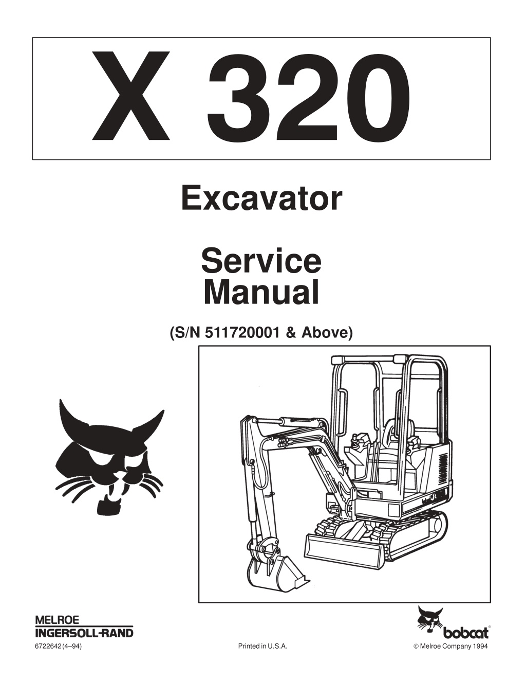
????? Excavator Service Manual (S/N 511720001 & Above) Melroe Company 1994 6722642 (4 94) Printed in U.S.A.
MAINTENANCE SAFETY Instructions are necessary before operating or servicing machine. Read and understand the Operation & Maintenance Manual, Operator s Handbook and signs (decals) on machine. Follow warnings and instructions in the manuals when making repairs, adjustments or servicing. Check for correct function after adjustments, repairs or service. Untrained operators and failure to follow instructions can cause injury or death. WARNING W-2003-0903 Safety Alert Symbol: This symbol with a warning statement, means: Warning, be alert! Your safety is involved! Carefully read the message that follows. CORRECT CORRECT CORRECT B-10731a B-14148 B-14142 Use the correct procedure to lift and support the excavator. Always lift the blade fully before installing jackstands. Never Hydraulic instructions. service Excavator the Bobcat without Cleaning and maintenance are required daily. WRONG WRONG WRONG B-14145 B-14141 B-14147 Have good ventilation when welding or grinding painted parts. Wear dust mask when grinding painted parts. Toxic dust and gas can be produced. Vent exhaust to outside when engine must be run for service. Exhaust system must be tightly sealed. Exhaust Fumes can kill without warning. Always lower the bucket and blade to the ground before doing any maintenance. Never modify equipment or add attachments not approved by Bobcat Company. WRONG WRONG WRONG B-14143 B-14146 B-6589 B-16102 B-16102 Stop, cool and clean engine of flammable materials checking fluids. Never service or adjust machine with the engine running unless instructed to do so in the manual. Avoid contact hydraulic fluid or diesel fuel under pressure. It can penetrate the skin or eyes. Never fill fuel tank with engine running, while smoking or when near open flame. Keep body, jewelry and clothing away from electrical contact, hot parts and exhaust. Wear eye protection to guard from battery acid, compressed springs, fluids under pressure and flying debris when engines are running or tools are used. Use eye protection approved for type of welding. Keep rear door closed except for service. Close and latch door before operating the excavator. Lead-acid flammable and explosive gases. Keep arcs, sparks, flames and lighted tobacco batteries. Batteries contain acid which burns eyes or skin on contact. Wear protective clothing. If acid contacts body, flush well with water. For eye contact flush well and get immediate attention. batteries produce before moving parts, away from with leaking medical Maintenance procedures which are given in the Operation & Maintenance Manual can be performed by the owner/ operator without any specific technical training. Maintenance procedures which are not in the Operation & Maintenance Manual must be performed ONLY BY QUALIFIED BOBCAT SERVICE PERSONNEL. Always use genuine Bobcat replacement parts. The Service Safety Training Course is available from your Bobcat dealer. MSW20-0805
CONTENTS PREVENTIVE MAINTENANCE SAFETY INSTRUCTIONS SERIAL NUMBER LOCATIONS DELIVERY REPORT HYDRAULIC EXCAVATOR IDENTIFICATION PREVENTIVE MAINTENANCE HYDRAULIC SYSTEM DRIVE SECTION . . . . . . . . . . . . . . . . . . . . . . . . . . . . . . . . . . . . . . . . . . . . . . . . UPPER WORKS & SWING SECTION MAIN FRAME & TRACKS . . . . . . . . . . . . . . . . . . . . . . . . . . . . . . . . . . . . . . . . . ELECTRICAL SYSTEM . . . . . . . . . . . . . . . . . . . . . . . . . . . . . . . . . . . . . . . . . . . ENGINE SERVICE . . . . . . . . . . . . . . . . . . . . . . . . . . . . . . . . . . . . . . . . . . . . . . . SPECIFICATIONS . . . . . . . . . . . . . . . . . . . . . . . . . . . . . . . . . . . . . . . . . . . . . . . . . . . . . . . . . . . . . . . . . . . . . . . . . . . . . . . . . . . . . . . . . . . . . . . . . . . . . . . . . . . . . . . . . . . . . . . . . . . . . . . . . . . . . . . . . . . . . . . . . . . . . . . . . . . . . . . . . . . . . . . . . . . . . . . . . . . . . . . . . . . . . . . . . . . . . . . . . . . . . . . . . . . . . . . . . . . . . . . . . . . . . . . . . . . . . . . . . . . . . . . . . . . . . . . . . . . . . . . . . . . . . . . . . . . . . . . . . . i ii ii iii HYDRAULIC SYSTEM 1 1 2 1 3 1 4 1 5 1 6 1 7 1 8 1 . . . . . . . . . . . . . . . . . . . . . . . . . . . . . . DRIVE SECTION UPPER WORKS & SWING SECTION MAIN FRAME & TRACKS ELECTRICAL SYSTEM ENGINE SERVICE SPECIFICATIONS 320 (S/N 511720001 & Above) Excavator 1 Service Manual
https://www.ebooklibonline.com Hello dear friend! Thank you very much for reading. Enter the link into your browser. The full manual is available for immediate download. https://www.ebooklibonline.com
FOREWORD This manual is for the Bobcat hydraulic excavator mechanic. It provides necessary servicing and adjustment procedures for the hydraulic excavator and its component parts and systems. Refer to the Operation & Maintenance Manual for operating instructions, starting procedure, daily checks, etc. A general inspection of the following items must be made after the hydraulic excavator has had service or repair: 1. Check that the ROPS/FOPS (Including sidescreens) is in good condition and is not modified. 9. Safety treads must in good condition. 2. Check that ROPS mounting hardware is tightened and is Melroe approved. 10. Check for correct function of indicator lamps (Optional on some models). 3. The seat belt must be correctly installed, functional and in good condition. 11. Check hydraulic fluid level, engine oil level and fuel supply. 12. Inspect for fuel, oil or hydraulic fluid leaks. 4. Inspect for loose or broken parts or connections. 5. Machine signs must be legible and in the correct location. 13. Lubricate the loader. 6. Steering levers, control levers and foot pedals must return to neutral. Check that foot pedals lock and control lever locks are in working condition. 14. Check the condition of the battery and cables. 7. Inspect the air cleaner for damage or leaks. Check the condition of the element. Recommend to the owner that all necessary corrections be made before the machine is returned to service. 8. Check the electrical charging system. 320 (S/N 511720001 & Above) Excavator i Service Manual
SAFETY INSTRUCTIONS Instructions are necessary before operating or servicing machine. Read Operation & Maintenance Manual, Handbook and signs (decals) on machine. Follow warnings and instructions in the manuals when making repairs, adjustments or servicing. Check for correct function after adjustments, repairs or service. Failure to follow instructions can cause injury or death. W 2003 0797 The following publications provide information on the safe use and maintenance of the loader and attachments: The Delivery Report is used to assure that complete instructions have been given to the new owner and that the machine is in safe operating condition. The Operation & Maintenance Manual delivered with the excavator gives operating information as well as routine maintenance and service procedures. It is a part of the excavator and must stay with the machine when it is sold. Replacement Operation & Maintenance Manuals can be ordered from your Bobcat Excavator dealer. The excavator has machine signs (decals) which instruct on the safe operation and care. The signs and their locations are shown in the Operation & Maintenance Manual. Replacement signs are available from your Bobcat Excavator dealer. The Bobcat Hydraulic Excavator has a plastic Operator s Handbook fastened to the operator cab. It s brief instructions are convenient to the operator. The handbook is available from your dealer in an English, French, German, Dutch, Italian, Spanish, Portugese, Finnish, Danish, and Swedish editions. The CIMA Safety Manual delivered with the excavator gives information for safe operating and standard signals. The Service Manual and Parts Manual are available from your dealer for use by mechanics to do shop type service and repair work. The Bobcat compact Excavator Operator Training Course is available through your local dealer. This course is intended to provide rules and practices of correct operation of the Hydraulic Excavator. Warnings on the machine and in the manuals are for your safety. Failure to obey warnings can cause injury or death. This notice identifies procedures which must be followed to avoid damage to the machine. I 2019 0284 W 2044 1285 Safety Alert Symbol: This Safety Symbol is used for important safety messages. When you see this symbol follow the safety message to avoid personal injury or death. 320 (S/N 511720001 & Above) Excavator iii Service Manual
SAFETY INSTRUCTIONS (Contd) Wear tight fitting clothing. Always wear safety glasses when maintaining or servicing the excavator. Safety glasses, hear- ing protection or loader special application kits are required for some work. See your dealer for Melroe Safety equipment. Know where fire extinguishers and first aid kits are located and how to use them. Do not use the Bobcat excavator where exhaust, arcs, sparks or hot components can contact flammable material, explosive dust or gases. The engine compartment and engine cooling system must be inspected every day and cleaned if necessary to prevent a fire hazard and overheating. Check all electrical wiring and connections for damage. Keep the battery terminals clean and tight. Repair or replace any damaged part. Check fuel and hydraulic tubes, hoses and fittings for damage and leakage. Never use open flame or bare skin to check for leaks. Tighten or replace any parts that show leakage. Always clean fluid spills. Do not use gasoline or diesel fuel for cleaning parts. Use commercial nonflammable solvents. Follow any environmental safety regulations when disposing of used fluids such as engine oil, grease or anti freeze. Do not use ether or starting fluids on an engine that has glow plugs. These starting aids can cause an explosion and injure you or bystanders. Always clean the excavator and disconnect the battery before doing any welding. Cover rubber hoses, battery and all other flammable parts. Keep a fire extinguisher near the excavator when welding. Have good ventilation when grinding or welding painted parts. Wear a dust mask when grinding painted parts. Toxic dust or gas can be produced. Stop the engine and let it cool before adding fuel. No smoking! Use the procedure in the Operation & Maintenance or Service Manuals for connecting the battery. Call Before You Dig 1 888 258 0808 When you call, you will be directed to a location in your state/city for information about burried lines (telephone, cable TV, water, sewer, gas,etc.). 320 (S/N 511720001 & Above) Excavator iv Service Manual
SERIAL NUMBER LOCATIONS A Always use the serial number of the loader when requesting service information or when ordering parts. Early or later models (identification made by serial number) may use different parts, or it may be necessary to use a different procedure in doing a specific service operation. HYDRAULIC EXCAVATOR SERIAL NUMBER The excavator serial number is on the front of the machine frame, to the left of the boom [A]. P 2216 ENGINE SERIAL NUMBER B The engine serial number is located on the engine block, near the fuel injection pump [B]. XXXX XXXXX P 0842 C DELIVERY REPORT The Delivery Report must be filled out by the dealer and signed by the owner or operator when the Bobcat loader is delivered. The form contents must be explained to the owner. Make sure it is filled out completely [C]. 320 (S/N 511720001 & Above) Excavator v Service Manual
HYDRAULIC EXCAVATOR IDENTIFICATION 320 Service Manual (S/N 511720001 & Above) #6722642 Content Section GRAB HANDLES CONTROL LEVERS (JOYSTICK) CANOPY (ROPS) ENGINE COVER UPPER STRUCTURE TRACK FRAME TRACK GRAB HANDLES OPERATORS HANDBOOK ARM CYLINDER BOOM OPERATOR SEAT AUXILIARY LINES BUCKET CYLINDER SEAT BELT ARM TOOL BOX (Operator s Manual Location) BUCKET LINK BLADE CYLINDER BUCKET BOOM CYLINDER BLADE B 14408 B 14407 320 (S/N 511720001 & Above) Excavator vi Service Manual
PREVENTIVE MAINTENANCE PREVENTIVE MAINTENANCE Page Number AIR CLEANER . . . . . . . . . . . . . . . . . . . . . . . . . . . . . . . . . . . . . . . . . . . . . . . . . 1 2 COOLING SYSTEM Coolant Level Coolant Replacement . . . . . . . . . . . . . . . . . . . . . . . . . . . . . . . . . . . . . . . . . . . . . . . . . . . . . . . . . . . . . . . . . . . . . . . . . . . . . . . . . . . . . . . . . . . 1 6 1 6 ENGINE COVER Opening the Cover . . . . . . . . . . . . . . . . . . . . . . . . . . . . . . . . . . . . . . . . . . . . 1 2 ENGINE LUBRICATION SYSTEM Engine Oil and Filter Replacement To Add Oil to Engine . . . . . . . . . . . . . . . . . . . . . . . . . . . . . . . . . . . . . . . . . . . . . . . . . . . . . . . . . . . . . . . . . . . . . . . . . 1 5 1 5 FUEL SYSTEM Fuel Filter Fuel System Service Maintenance Removing Air From the Fuel System . . . . . . . . . . . . . . . . . . . . . . . . . . . . . . . . . . . . . . . . . . . . . . . . . . . . . . . . . . . . . . . . . . . . . . . . . . . . . . . . . . . . . . . . . . . . . . . . . . . . . . . . . . . . . . . . . . . . . . . . . . . . . . . . . . . . . . . . . . . . . . . . . . . . . . . . . . . . . . . . . . . . . . . . . . . . . 1 4 1 3 1 3 1 4 HYDRAULIC SYSTEM Checking and Adding Fluid Diagnostic Couplers Hydraulic Reservoir Replacement of the Hydraulic Filter . . . . . . . . . . . . . . . . . . . . . . . . . . . . . . . . . . . . . . . . . . . . . . . . . . . . . . . . . . . . . . . . . . . . . . . . . . . . . . . . . . . . . . . . . . . . . . . . . . . . . . . . . . . . . . . . . . . . . . . . . . . . . . . . . . . . . . . . . . . . . . . . . . . . . . . . . 1 7 1 7 1 8 1 8 LUBRICATION OF THE HYDRAULIC EXCAVATOR Procedure . . . . . . . . . . . . . . . . . . . . . . . . . . . . . . . . . . . . . . . . . . . . . . . . . . . . 1 10 SERVICE SCHEDULE Chart . . . . . . . . . . . . . . . . . . . . . . . . . . . . . . . . . . . . . . . . . . . . . . . . . . . . . . . . 1 1 USING A BOOSTER BATTERY (JUMP STARTING) Procedure . . . . . . . . . . . . . . . . . . . . . . . . . . . . . . . . . . . . . . . . . . . . . . . . . . . . 1 9
SERVICE SCHEDULE Maintenance work must be done at regular intervals. Failure to do so will result in excessive wear and early failures. The service schedule is a guide for correct maintenance of the Hydraulic Excavator. Instructions are necessary before operating or servicing machine. Read Operation & Maintenance Manual, Handbook and signs (decals) on machine. Follow warnings and instructions in the manuals when making repairs, adjustments or servicing. Check for correct function after adjustments, repairs or service. Failure to follow instructions can cause injury or death. W 2003 1089 ITEM SERVICE REQUIRED 8 10 50 100 250 500 1000 Engine Air Cleaner Engine Oil Engine Coolant System Indicator Lights Operator Canopy Seat Belt Safety Signs (Decals) Tracks Hydraulic Reservoir All Machinery Pivot Points Fuel Tank/Fuel Filter Swing Circle Swing Pinion Engine Oil & Filter Alternator Belt Hydraulic Filter Fuel Filter Battery Air Cleaner Cooling System Alternator & Starter Engine Valve Clearance Cooling System Case Drain Return Screen Hydraulic Tank Final Drive Case Check & empty dust cup as required. Check the oil level & add oil as needed. Check radiator coolant level. Check for correct operation. Check the fastening bolts, nuts, & condition of cab. Check the condition & that fasteners are tight. Check for damaged signs (decals) replace as needed. Check & adjust tension. Check fluid level. Lubricate 22 grease fittings. Drain water and sediment from fuel tank/filter. Lubricate two grease fittings. Lubricate one grease fitting. Replace oil & filter element. Check & adjust tension. Replace filter element. Replace filter element. Check & clean cable ends & check electrolyte level. Replace the filter element. Clean the radiator fins. Check the condition. Check & adjust valve clearance. Drain, flush & add new coolant to the cooling system. Clean the screen with solvent. Change the fluid, clean fill neck strainer. Change the oil. After the first 250 hours of machine operation do the following: Change oil in final drive case. Check and adjust engine valve clearance. 320 (S/N 511720001 & Above) Excavator 1 1 Service Manual
ENGINE COVER A Opening the Cover AVOID INJURY Never service or adjust the machine when the engine is running unless instructed to do so in this manual. W 2012 0290 P 2218 Keep the engine cover closed when operating the machine. B W 2141 0189 Open the engine cover to service the engine. Pull on the latch and lift the engine cover up until it is fully raised [A] AIR CLEANER SERVICE See the Service Schedule Page 1 3 for the correct service interval. Service the air cleaner as follows: P 2188 Daily Check: 1. Loosen the clamp on the air cleaner [B]. C 2. Remove the cover (Item 1) [C]. Empty the dust cup. Visually inspect the filter element. Do Not remove the element unless plugged and replacement is necessary. 3 Filter Replacement: 3. Remove the wing Nut (Item 3) [C]. 2 1 P 2185 4. Remove the filter element [D]. D 5. Check the air cleaner housing for damage. 1 6. Wipe the canister clean with a clean cloth. Do Not use compressed air. 7. Check the seal (Item 1) [D]. 8. Install a new air filter element. Install and tighten the wing nut. 9. Install the dust cup and cover so the arrow points up. 10. Check that all the air cleaner hose clamps are tight. P 2187 320 (S/N 511720001 & Above) Excavator 1 2 Service Manual
FUEL SYSTEM A Use Number 2 diesel fuel in the engine. When the temperature goes below 14 F ( 10 C), Number 1 fuel can be used. (See fuel, coolant and lubricants chart, Page 8 1.) 2 1 Stop and cool the engine before adding fuel, NO SMOKING! Failure to obey warnings can cause an explosion or fire. P 0805 W 2063 0887 B Fuel System Service The fuel level in the tank is indicated by the fuel gauge (Item 1) [A] when the ignition key in in the ON position. NOTE: When the fuel level reaches the 1/8 fuel setting, the low fuel light (Item 2) [A] will come ON to alert the operator of this condition. Use the key to un lock the fuel fill door [B]. Turn the fill cap to remove it [C]. Use a clean, approved safety container to add fuel to the tank. P 2208 Add fuel only in an area that has a free movement of air and no open flames or sparks. NO SMOKING! C After the tank is full, install and tighten the fuel fill cap. Close and lock the fuel fill door. Always clean up spilled fuel or oil. Keep heat, flames, sparks or lighted tobacco away from fuel and oil. Failure to use care around combustibles can cause explosion or fire which can result in injury or death. P 2206 W 2103 1285 D Maintenance The excavator is equipped with a fuel drain valve in the bottom of the fuel tank. 1 Turn the upperstructure until access to the bottom of the fuel tank is available [D]. Open the drain valve (Item 1) [D] and drain all water and sediment into a container. NOTE: A hose can be installed onto the drain valve to prevent fuel from spilling while draining the tank. P 2187 320 (S/N 511720001 & Above) Excavator 1 3 Service Manual
A FUEL SYSTEM(Cont d) Fuel Filter See the Service Schedule Page 1 3 for the service interval. To remove water from filter, open drain valve (Item 1) [A] at the bottom of the fuel filter. Drain water and sediment into a container. Use a filter wrench to remove the fuel filter element [A]. 1 Cleaner filter housing surface. Put clean oil on the filter gasket. Install the new element and hand tighten only. P 2217 Removing Air from the Fuel System B After replacing the fuel filter or when the fuel tank has run out of fuel, the air must be removed from the fuel system. Open the vent (Item 1) on the fuel filter housing [B]. 1 P 0727 Open the bleed screw on the top of the fuel filter housing (Item 1) [C]. C 1 Squeeze the primer bulb to fill the filter [D]. P 2350 When fuel, free of air bubbles, emerges from the filter housing, close the bleed screw (Item 1) [C]. D Leave the vent (Item 1) [B] on the injection pump open slightly. Start the engine. When the engine runs smoothly, close the vent screw on the injection pump. NOTE: If engine fails to start after the above procedure is performed, it will be necessary to bleed the injector lines; do the following: 1. Loosen the three (3) injector line locknuts, one turn. 2. While cranking the engine and fuel emerges from the injector lines, slowly tighten the injector line lock nuts. P 2184 320 (S/N 511720001 & Above) Excavator 1 4 Service Manual
ENGINE LUBRICATION SYSTEM A Check the engine oil every day. Stop the engine. Open the engine cover. Remove the dipstick [A]. Keep the oil level between the marks on the dipstick. Use a good quality motor oil that meets API Service Clarification of CE or CD. (See Fuel, Coolant and Lubricants Chart, Page 8 1.) P 2194 Engine Oil and Filter Replacement B See the Service Schedule Page 1 3 for the correct service interval. Use the following procedure to change the oil and filter: 1. Run the engine until it is at operating temperature. 2. Turn the upperstructure so there is clearance for the engine oil drain plug between the tracks. Stop the engine. 1 3. Remove the drain plug (Item 1) [B]. Drain the oil into a container. P 2231 NOTE: Some excavators may have a field installed belly pan (available from Melroe Parts). This belly pan has a rectangular hole for access to the oil pan drain plug. C 4. Remove the oil filter (Item 1) [C], using a filter wrench. 5. Clean the filter housing surface. Put clean oil on the filter gasket. Install the new filter and hand tighten only. 1 6. Install and tighten the oil drain plug. P 2191 To Add Oil to Engine: D 7. Remove the dipstick [A]. 8. Remove the dipstick fill tube cap [D]. P 2195 320 (S/N 511720001 & Above) Excavator 1 5 Service Manual
ENGINE LUBRICATION SYSTEM (Contd) A To Add Oil to Engine (Cont d) 9. Install a funnel into the dipstick fill tube [A]. Put 4.5 quarts (4,3 L) of oil into the engine. (See Fuel, Coolant and Lubricants Chart, Page 8 1.) 10. Start the engine and let it run for several minutes. Stop the engine. Check for leaks at the oil filter and drain plug. 11. Check the oil level and add oil as needed to bring it to the top mark on the dipstick. Optional engine oil fill location [B]. The valve cover oil fill cap can be used for adding oil in place of the dipstick tube. Use protective, heat resistant shield over the muffler to protect yourself from the HOT muffler. P 2196 B COOLING SYSTEM Coolant Level When the engine is cool, remove the radiator cap [C]. The coolant level must be 3/4 1 inch (19 25 mm) below the filler neck at the radiator. If the coolant level is low, add pre mixed coolant (50% water and 50% ethylene glycol) to the radiator. Coolant Replacement P 2209 C Do not remove radiator cap when the engine is hot. You can be seriously burned. W 2070 1285 Wear safety glasses to prevent eye injury when any of the following conditions exist: When fluids are under pressure. Flying debris or loose material is present. Engine is running. Tools are being used. W 2019 1285 1. Turn the upperstructure so there is access to the engine and radiator from underneath. Stop the engine. 2. Loosen and remove the radiator cap [C]. 3. Open the radiator drain valve (Item 1) [D]. 4. Drain all the coolant from the system. 5. When all the coolant is removed, close the drain valve. 6. Pre mix 50% water and 50% ethylene glycol in a separate container. Fill the radiator with the pre mixed coolant until it is full. 7. Run the engine at idle speed for about 5 10 minutes to remove the air from the cooling system (leave the radiator cap off during this operation). 8. Stop the engine. Check the coolant level and add as needed to bring it 3/4 1 inch (19 25 mm) below the filler neck. Install the radiator cap and tighten. P 2199 D 1 P 2198 320 (S/N 511720001 & Above) Excavator 1 6 Service Manual
HYDRAULIC SYSTEM A Checking and Add Fluid To check and add hydraulic fluid to the reservoir, use the following procedure: 1 Prior to checking the hydraulic fluid level, retract the arm and bucket cylinder, put the bucket on the ground and raise the blade. P 2203 I 2076 0795 B 1. Put the machine on a flat level surface. 2. Retract the arm and bucket cylinders, put the bucket on the ground and raise the blade. Stop the engine. 3. The hydraulic fluid level must be visible in the sight gauge (Item 1) [A]. 4. If fluid level is not correct, open the hydraulic fill door and remove the hydraulic cap [B]. P 2192 C 5. Remove the screen from the fill neck and replace it if damaged [C].Install the screen before adding fluid. 6. Add the correct fluid to the reservoir until it is visible in the center of the sight gauge [A]. (See Fuel, Coolant and Lubricants Chart, Page 8 1.) 7. Install the reservoir cap. P 2204 Diagnostic Couplers D Diagnostic couplers are located at each hydraulic pump (Item 1) [D]. The couplers can be used to check circuit pressures. Refer to Page 2 1 for test procedure and tools needed for testing. 1 P 2341 320 (S/N 511720001 & Above) Excavator 1 7 Service Manual
HYDRAULIC SYSTEM (Contd) A Prior to checking the hydraulic fluid level, retract the arm and bucket cylinder, put the bucket on the ground and raise the blade. 1 I 2076 0795 P 2189 Replacement of the Hydraulic Filter See the Service Schedule Page 1 3 for the correct service interval. B 1. Open the engine cover. 2. Use a filter wrench and remove the filter element (Item 1) [A]. 3. Clean the housing where the filter gasket makes contact. 1 4. Put clean hydraulic fluid on the gasket. Install the new filter element and hand tighten only. 5. Start the engine. Run the machine through the hydraulic functions. Stop the engine. Check the fluid level at the reservoir and add as needed. Check the filter area for leaks. Hydraulic Reservoir P 2226 Replacement of the Hydraulic Fluid See the Service Schedule Page 1 3 for the correct service interval. 1. Turn the upperstructure until the reservoir drain valve is between the tracks. Always clean up spilled fuel or oil. Keep heat, flames, sparks or lighted tobacco away from fuel and oil. Failure to use care around combustibles can cause explosion or fire which can result in injury or death. 2. Retract the arm and bucket cylinder, lower the bucket to the ground. Stop the engine. W 2103 1285 3. Remove the hydraulic filter element [A]. 4. Remove the drain plug (Item 1) [B] from the bottom of the reservoir. 5. Drain the fluid into a container (approximately 3.65 gals. (13.8 L). 6. Install the drain plug. 7. Install a new hydraulic filter. 8. Add the correct fluid to the reservoir until it is visible in the sight gauge (approximately 3.65 gals. (13,8 L.) to fill only the reservoir). (See Fuel, Coolant and Lubricants Chart, Page 8 1.) 9. Run the machine through the hydraulic functions. Stop the engine. Check the fluid level and add as needed. 320 (S/N 511720001 & Above) Excavator 1 8 Service Manual
USING A BOOSTER BATTERY (JUMP STARTING) A Procedure If it is necessary to use a booster battery to start the engine, BE CAREFUL! Make sure the swing locking lever is in the engaged position. The key switch must be in the OFF position. The booster battery must be 12 volt. Open the engine cover [A]. P 2218 Connect the end of the first cable to the positive (+) terminal of the booster battery. Connect the other end of the same cable to the starter positive (+) battery cable terminal (Item 1) [B] & [C]. B Connect the end of the second cable to the negative ( ) terminal of the booster battery. Connect the other end of the same cable to the machine frame (Item 2) [B] & [C]. NOTE: Also see Cold Starting Procedure, in Operation & Maintenance Manual. 1 2 Start the engine. After the engine is running, remove the cable (Item 2) [B] & [C] connected to the frame first. Disconnect the cable from the starter terminal (Item 1) [B] & [C]. P 2215 C If jump starting the excavator from a second machine: When jump starting the excavator from a battery installed in a second machine. Make sure that the second machine is NOT running while using the glow plugs. High voltage spikes from a running machine can burn out the glow plugs. 1 2 I 2060 0195 P 2213 Damage to the alternator can occur if: Engine is operated with battery cables disconnected. Battery cables are connected when using a fast charger or when welding on the loader (Remove both cables from the battery). Extra battery cables (booster cables) are connected wrong. Keep arcs, sparks, flames and lighted tobacco away from batteries. When jumping from booster battery make (negative) at engine frame. final connection Do not jump start or charge a frozen battery. Warm battery to 60 F. (16 C.) before connecting to a charger. Unplug charger before connecting or disconnecting cables to battery. I 2023 1285 Battery gas can explode and cause serious injury. W 2066 0490 320 (S/N 511720001 & Above) Excavator 1 9 Service Manual
LUBRICATION OF THE HYDRAULIC EXCAVATOR A Procedure 1 Lubricate the Hydraulic Excavator as specified in the Service Schedule Page 1 1 for the best performance of the machine. Always use a good quality lithium based multi purpose grease when lubricated the machine. Apply the lubricant until extra grease shows. 2 Ref. Description (# of Fittings) 3 1. Blade Cylinder Rod End, every 8 10 hours (1) [A]. 2. Blade Pivots, every 8 10 hours (2) [A]. 3. Blade Cylinder Base End, every 8 10 hours (1) [A]. P 2224 B 4. Boom Swing Cylinder Rod End, every 8 10 hours (1) [B]. 5. Boom Cylinder Base End, every 8 10 hours (1) [B]. 6. Boom Base Pivot, every 8 10 hours (1) [B]. 7. Swing Circle Pinion, every 50 hours (1) [B], Install 4 pumps of grease from a grease gun into the grease fitting. Rotate the upperstructure 180 and install 4 more pumps of grease into the grease fitting. 6 7 5 4 P 2222 C 8. Boom Swing Bracket Pivot, every 8 10 hours (2) [C]. 9. Frame Swing Bracket Pivot, every 8 10 hours (1) [C]. 9 8 P 2228 D 10. Boom Cylinder Rod End, every 8 10 hours (1) [D]. 11. Arm Cylinder Base End, every 8 10 hours (1) [D]. 12. Arm Cylinder Rod End, every 8 10 hours (1) [D]. 13. Arm Base Pivot, every 8 10 hours (1) [D]. 14. Bucket Cylinder Base End, every 8 10 hours (1) [D]. 12 13 11 14 10 P 2220 320 (S/N 511720001 & Above) Excavator 1 10 Service Manual
LUBRICATION OF THE HYDRAULIC EXCAVATOR (Cont d) A 16 Procedure (Cont d) Ref. Description (# of Fittings) 17 15 15. Bucket Cylinder Rod End, every 8 10 hours (1) [A]. 16. Bucket Link Pivots, every 8 10 hours (2) [A]. 17. Bucket Pivots, every 8 10 hours (3) [A]. P 2223 B 18. Boom Swing Cylinder End, every 8 10 hours (1) [B]. 18 P 2227 C 19. Swing Circle Ball Bearing, every 50 hours (2) [C] & [D]. Located 180 degrees apart on the bearing. NOTE: Do Not overgrease the swing circle or damage to the seal could result, Install 4 to 5 pumps of grease gun into each of the 2 grease fittings. Rotate the upperstructure 90 and install 4 to 5 pumps of grease into each of the 2 grease fittings. 19 P 2230 D 19 CD 9144 320 (S/N 511720001 & Above) Excavator 1 11 Service Manual
HYDRAULIC SECTION Page Number ARM CYLINDER Removal And Installation . . . . . . . . . . . . . . . . . . . . . . . . . . . . . . . . . . . . . . . 2 71 AUXILIARY COUPLERS Removal And Installation HYDRAULIC SYSTEM . . . . . . . . . . . . . . . . . . . . . . . . . . . . . . . . . . . . . . . 2 84 BLADE CYLINDER Removal And Installation . . . . . . . . . . . . . . . . . . . . . . . . . . . . . . . . . . . . . . . 2 73 BOOM CYLINDER Boom Cylinder Shield Removal And Installation . . . . . . . . . . . . . . . . . . . . . . . . . . . . . . . . . . . . . . . . . . . . . . . . . . . . . . . . . . . . . . . . . . . . . . . . . . . . . . . . . 2 70 2 70 BOOM SWING CYLINDER Removal And Installation . . . . . . . . . . . . . . . . . . . . . . . . . . . . . . . . . . . . . . . 2 74 BUCKET CYLINDER Removal And Installation . . . . . . . . . . . . . . . . . . . . . . . . . . . . . . . . . . . . . . . 2 72 DRAIN BLOCK Filter Screen Removal And Installation . . . . . . . . . . . . . . . . . . . . . . . . . . . . . . . . . . . . . . . . . . . . . . . . . . . . . . . . . . . . . . . . . . . . . . . . . . . . . . . . . . . . . . . . . 2 88 2 88 HYDRAULIC CONTROL VALVE (6 Spool) DUKES VALVE (S/N 511720001 511721411) Assembly . . . . . . . . . . . . . . . . . . . . . . . . . . . . . . . . . . . . . . . . . . . . . . . . . . . Disassembly . . . . . . . . . . . . . . . . . . . . . . . . . . . . . . . . . . . . . . . . . . . . . . . . . Inlet Section (R.H. & L.H. Travel) Assembly . . . . . . . . . . . . . . . . . . . . . . . . . . . . . . . . . . . . . . . . . . . . . . . . . . Disassembly . . . . . . . . . . . . . . . . . . . . . . . . . . . . . . . . . . . . . . . . . . . . . . . . Main Relief Valve Adjustment . . . . . . . . . . . . . . . . . . . . . . . . . . . . . . . . . . . . . . . . . . . . . . . . . Assembly . . . . . . . . . . . . . . . . . . . . . . . . . . . . . . . . . . . . . . . . . . . . . . . . . . Disassembly . . . . . . . . . . . . . . . . . . . . . . . . . . . . . . . . . . . . . . . . . . . . . . . . Parts Identification . . . . . . . . . . . . . . . . . . . . . . . . . . . . . . . . . . . . . . . . . . . Port Relief Valve Adjustment . . . . . . . . . . . . . . . . . . . . . . . . . . . . . . . . . . . . . . . . . . . . . . . . . Assembly . . . . . . . . . . . . . . . . . . . . . . . . . . . . . . . . . . . . . . . . . . . . . . . . . . Disassembly . . . . . . . . . . . . . . . . . . . . . . . . . . . . . . . . . . . . . . . . . . . . . . . . Removal And Installation . . . . . . . . . . . . . . . . . . . . . . . . . . . . . . . . . . . . . . Valve Sections (Auxiliary) Assembly . . . . . . . . . . . . . . . . . . . . . . . . . . . . . . . . . . . . . . . . . . . . . . . . . . Disassembly . . . . . . . . . . . . . . . . . . . . . . . . . . . . . . . . . . . . . . . . . . . . . . . . Valve Sections (Boom, Bucket and Arm) Assembly . . . . . . . . . . . . . . . . . . . . . . . . . . . . . . . . . . . . . . . . . . . . . . . . . . Disassembly . . . . . . . . . . . . . . . . . . . . . . . . . . . . . . . . . . . . . . . . . . . . . . . . 2 23 2 16 2 18 2 17 2 26 2 26 2 26 2 15 2 24 2 24 2 24 2 14 2 22 2 21 2 20 2 19 HYDRAULIC CONTROL VALVE (3 Spool) DUKES VALVE (S/N 511720001 511721411) Assembly . . . . . . . . . . . . . . . . . . . . . . . . . . . . . . . . . . . . . . . . . . . . . . . . . . . Build Up Valve Assembly . . . . . . . . . . . . . . . . . . . . . . . . . . . . . . . . . . . . . . . . . . . . . . . . . . Disassembly . . . . . . . . . . . . . . . . . . . . . . . . . . . . . . . . . . . . . . . . . . . . . . . . Disassembly . . . . . . . . . . . . . . . . . . . . . . . . . . . . . . . . . . . . . . . . . . . . . . . . . 2 36 2 37 2 37 2 29 Continued On Next Page Revised June 98 320 (S/N 511720001 & Above) Excavator Service Manual
HYDRAULIC SECTION (Contd) Page Number HYDRAULIC CONTROL VALVE (3 Spool) DUKES VALVE (S/N 511720001 511721411) (Cont d) End Cover (Boom Swing) and Valve Section (Blade) Assembly . . . . . . . . . . . . . . . . . . . . . . . . . . . . . . . . . . . . . . . . . . . . . . . . Disassembly . . . . . . . . . . . . . . . . . . . . . . . . . . . . . . . . . . . . . . . . . . . . . . Inlet Section (Housing Swing) Assembly . . . . . . . . . . . . . . . . . . . . . . . . . . . . . . . . . . . . . . . . . . . . . . . . Disassembly . . . . . . . . . . . . . . . . . . . . . . . . . . . . . . . . . . . . . . . . . . . . . . Load Check Block Assembly . . . . . . . . . . . . . . . . . . . . . . . . . . . . . . . . . . . . . . . . . . . . . . . . Disassembly . . . . . . . . . . . . . . . . . . . . . . . . . . . . . . . . . . . . . . . . . . . . . . Main Relief Valve Adjustment . . . . . . . . . . . . . . . . . . . . . . . . . . . . . . . . . . . . . . . . . . . . . . . Assembly . . . . . . . . . . . . . . . . . . . . . . . . . . . . . . . . . . . . . . . . . . . . . . . . Disassembly . . . . . . . . . . . . . . . . . . . . . . . . . . . . . . . . . . . . . . . . . . . . . . Parts Identification . . . . . . . . . . . . . . . . . . . . . . . . . . . . . . . . . . . . . . . . . . Removal And Installation . . . . . . . . . . . . . . . . . . . . . . . . . . . . . . . . . . . . . 2 33 2 31 2 30 2 30 2 35 2 35 2 38 2 38 2 38 2 28 2 27 HYDRAULIC CONTROL VALVE (6 Spool) HUSCO VALVE (S/N 511721412 & Above) Assembly . . . . . . . . . . . . . . . . . . . . . . . . . . . . . . . . . . . . . . . . . . . . . . . . . Auxiliary Section Assembly . . . . . . . . . . . . . . . . . . . . . . . . . . . . . . . . . . . . . . . . . . . . . . . . Disassembly . . . . . . . . . . . . . . . . . . . . . . . . . . . . . . . . . . . . . . . . . . . . . . Boom, Bucket & Arm Section Assembly . . . . . . . . . . . . . . . . . . . . . . . . . . . . . . . . . . . . . . . . . . . . . . . . Disassembly . . . . . . . . . . . . . . . . . . . . . . . . . . . . . . . . . . . . . . . . . . . . . . Disassembly . . . . . . . . . . . . . . . . . . . . . . . . . . . . . . . . . . . . . . . . . . . . . . . Inlet Section Disassembly And Assembly Parts Identification . . . . . . . . . . . . . . . . . . . . . . . . . . . . . . . . . . . . . . . . . Right Hand And Left Hand Travel Section Assembly . . . . . . . . . . . . . . . . . . . . . . . . . . . . . . . . . . . . . . . . . . . . . . . . Disassembly . . . . . . . . . . . . . . . . . . . . . . . . . . . . . . . . . . . . . . . . . . . . . . 2 50 2 49 2 48 2 46 2 45 2 40 2 41 2 39 . . . . . . . . . . . . . . . . . . . . . . 2 43 2 42 HYDRAULIC CONTROL VALVE (3 Spool) HUSCO VALVE (S/N 511721412 & Above) Assembly . . . . . . . . . . . . . . . . . . . . . . . . . . . . . . . . . . . . . . . . . . . . . . . . . Blade And Boom Swing Section Assembly . . . . . . . . . . . . . . . . . . . . . . . . . . . . . . . . . . . . . . . . . . . . . . . . Disassembly . . . . . . . . . . . . . . . . . . . . . . . . . . . . . . . . . . . . . . . . . . . . . . Lockout Valve Assembly . . . . . . . . . . . . . . . . . . . . . . . . . . . . . . . . . . . Lockout Valve Disassembly . . . . . . . . . . . . . . . . . . . . . . . . . . . . . . . . . Build Up Valve Assembly . . . . . . . . . . . . . . . . . . . . . . . . . . . . . . . . . . . . Build Up Valve Disassembly . . . . . . . . . . . . . . . . . . . . . . . . . . . . . . . . . Build Up Valve Test Procedure . . . . . . . . . . . . . . . . . . . . . . . . . . . . . . . Disassembly . . . . . . . . . . . . . . . . . . . . . . . . . . . . . . . . . . . . . . . . . . . . . . . . Parts Identification . . . . . . . . . . . . . . . . . . . . . . . . . . . . . . . . . . . . . . . . . . Swing Motor Valve Section Assembly . . . . . . . . . . . . . . . . . . . . . . . . . . . . . . . . . . . . . . . . . . . . . . . . . Disassembly . . . . . . . . . . . . . . . . . . . . . . . . . . . . . . . . . . . . . . . . . . . . . . . 2 67 2 62 2 60 2 64 2 63 2 69 2 69 2 69 2 59 2 58 2 66 2 65 HYDRAULIC CYLINDER Disassembly Assembly . . . . . . . . . . . . . . . . . . . . . . . . . . . . . . . . . . . . . . . . . . . . . . . . . . . . . . . . . . . . . . . . . . . . . . . . . . . . . . . . . . . . . . . . . . . . . . . . . . 2 75 2 79 Continued On Next Page 320 (S/N 511720001 & Above) Excavator 2 2o Service Manual Revised June 98
MORE MANUALS: https://www.ebooklibonline.com/ Suggest: If the above button click is invalid. Please download this document first, and then click the above link to download the complete manual. Thank you so much for reading
HYDRAULIC SECTION (Contd) Page Number HYDRAULIC FILTER ASSEMBLY Removal And Installation . . . . . . . . . . . . . . . . . . . . . . . . . . . . . . . . . . . . . 2 84 HYDRAULIC PUMP Assembly Disassembly Hydraulic Pump Assembly . . . . . . . . . . . . . . . . . . . . . . . . . . . . . . . . . . . . . . . . . . . . . . . . . . . . . . . . . . . . . . . . . . . . . . . . . . . . . . . . . . . . . . . . . . . . . . . . . . . . . . . . . . . . . . . . . . . . . . . . . . . . . . . . . . . . . . 2 11 2 9 2 8 HYDRAULIC SERVICE INFORMATION Checking The Hydraulic Pump Checking The Main Relief Valve . . . . . . . . . . . . . . . . . . . . . . . . . . . . . . . . . . . . . . . . . . . . . . . . . . . . . . . . . . . . . . . 2 7 2 6 HYDRAULIC SYSTEM TROUBLESHOOTING Charts . . . . . . . . . . . . . . . . . . . . . . . . . . . . . . . . . . . . . . . . . . . . . . . . . . . . . 2 1 JOYSTICK MANIFOLD WITH ACCUMULATOR Description . . . . . . . . . . . . . . . . . . . . . . . . . . . . . . . . . . . . . . . . . . . . . . . . . Disassembly And Assembly . . . . . . . . . . . . . . . . . . . . . . . . . . . . . . . . . . Removal And Installation . . . . . . . . . . . . . . . . . . . . . . . . . . . . . . . . . . . . . 2 85 2 87 2 85 JOYSTICK CONTROL CHANGE ISO to Standard Standard to ISO . . . . . . . . . . . . . . . . . . . . . . . . . . . . . . . . . . . . . . . . . . . . . . . . . . . . . . . . . . . . . . . . . . . . . . . . . . . . . . . . . . . . . . . . . . 2 90 2 90 MAIN RELIEF VALVES HUSCO VALVE Adjusting The Main Relief Valves Assembly . . . . . . . . . . . . . . . . . . . . . . . . . . . . . . . . . . . . . . . . . . . . . . . . . . Disassembly . . . . . . . . . . . . . . . . . . . . . . . . . . . . . . . . . . . . . . . . . . . . . . . . Parts Identification . . . . . . . . . . . . . . . . . . . . . . . . . . . . . . . . . . . . . . . . . . . . . . . . . . . . . . . . . . . . . . . . . . . . . . . . 2 57 2 56 2 56 2 55 OIL COOLER Removal And Installation . . . . . . . . . . . . . . . . . . . . . . . . . . . . . . . . . . . . . 2 89 PORT RELIEF VALVES HUSCO VALVE Adjustment . . . . . . . . . . . . . . . . . . . . . . . . . . . . . . . . . . . . . . . . . . . . . . . . . Assembly . . . . . . . . . . . . . . . . . . . . . . . . . . . . . . . . . . . . . . . . . . . . . . . . . . Disassembly . . . . . . . . . . . . . . . . . . . . . . . . . . . . . . . . . . . . . . . . . . . . . . . . Parts Identification . . . . . . . . . . . . . . . . . . . . . . . . . . . . . . . . . . . . . . . . . . 2 54 2 54 2 53 2 52 320 (S/N 511720001 & Above) Excavator 2 1 Service Manual Revised June 98
https://www.ebooklibonline.com Hello dear friend! Thank you very much for reading. Enter the link into your browser. The full manual is available for immediate download. https://www.ebooklibonline.com


")


")

")
")


")

")