Caterpillar Cat CS-583 VIBRATORY COMPACTOR (Prefix 8YJ) Service Repair Manual Instant Download (8YJ00001 and up)
Please open the website below to get the complete manualnn// n

Download Presentation

Please find below an Image/Link to download the presentation.
The content on the website is provided AS IS for your information and personal use only. It may not be sold, licensed, or shared on other websites without obtaining consent from the author. Download presentation by click this link. If you encounter any issues during the download, it is possible that the publisher has removed the file from their server.
E N D
Presentation Transcript
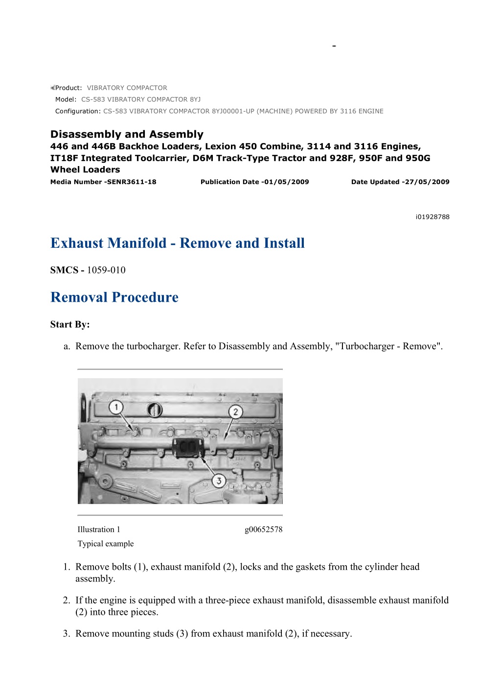
CS-583 VIBRATORY COMPACTOR 8YJ00001-UP (MACHINE) POWERED BY 3... 1/4 Product: VIBRATORY COMPACTOR Model: CS-583 VIBRATORY COMPACTOR 8YJ Configuration: CS-583 VIBRATORY COMPACTOR 8YJ00001-UP (MACHINE) POWERED BY 3116 ENGINE Disassembly and Assembly 446 and 446B Backhoe Loaders, Lexion 450 Combine, 3114 and 3116 Engines, IT18F Integrated Toolcarrier, D6M Track-Type Tractor and 928F, 950F and 950G Wheel Loaders Media Number -SENR3611-18 Publication Date -01/05/2009 Date Updated -27/05/2009 i01928788 Exhaust Manifold - Remove and Install SMCS - 1059-010 Removal Procedure Start By: a. Remove the turbocharger. Refer to Disassembly and Assembly, "Turbocharger - Remove". Illustration 1 g00652578 Typical example 1. Remove bolts (1), exhaust manifold (2), locks and the gaskets from the cylinder head assembly. 2. If the engine is equipped with a three-piece exhaust manifold, disassemble exhaust manifold (2) into three pieces. 3. Remove mounting studs (3) from exhaust manifold (2), if necessary. https://127.0.0.1/sisweb/sisweb/techdoc/techdoc_print_page.jsp?returnurl=/sis... 2021/7/18
CS-583 VIBRATORY COMPACTOR 8YJ00001-UP (MACHINE) POWERED BY 3... 2/4 Installation Procedure Table 1 Required Tools Tool Part Number Part Description Qty A 5P-3931 Anti-Seize Compound 1 B 2P-2333 High Temperature Sealer 1 Illustration 2 g00652578 Typical example 1. Apply Tooling (A) to the threads of mounting studs (3). 2. Install mounting studs (3). Tighten mounting studs (3) to a torque of 35 5 N m (26 4 lb ft). 3. If the engine is equipped with a three-piece exhaust manifold, apply a thin coat of Tooling (B) to the male ends of exhaust manifold (2). Coat the inside of the female ends of exhaust manifold (2) with clean engine oil. Assemble exhaust manifold (2) and remove the excess sealant from the joints. 4. Install new exhaust manifold gaskets. 5. Apply Tooling (A) to the threads of bolts (1). Position the gaskets and exhaust manifold (2) on the cylinder head assembly. Install locks and bolts (1). https://127.0.0.1/sisweb/sisweb/techdoc/techdoc_print_page.jsp?returnurl=/sis... 2021/7/18
CS-583 VIBRATORY COMPACTOR 8YJ00001-UP (MACHINE) POWERED BY 3... 3/4 Illustration 3 g00617739 Typical example of a three-piece exhaust manifold Illustration 4 g00641026 Exhaust manifold for a Four cylinder engine https://127.0.0.1/sisweb/sisweb/techdoc/techdoc_print_page.jsp?returnurl=/sis... 2021/7/18
https://www.ebooklibonline.com Hello dear friend! Thank you very much for reading. Enter the link into your browser. The full manual is available for immediate download. https://www.ebooklibonline.com
CS-583 VIBRATORY COMPACTOR 8YJ00001-UP (MACHINE) POWERED BY 3... 4/4 Illustration 5 g00641092 Water cooled exhaust manifold 6. Tighten bolts (1) in a numerical sequence to a torque of 4 1 N m (35 9 lb in). 7. Tighten bolts (1) in a numerical sequence to a torque of 45 5 N m (33 4 lb ft). Illustration 6 g00675760 Typical example of locking tabs 8. Bend the locking tabs (4) over the flat of each bolt head. End By: a. Install the turbocharger. Refer to Disassembly and Assembly, "Turbocharger - Install". https://127.0.0.1/sisweb/sisweb/techdoc/techdoc_print_page.jsp?returnurl=/sis... 2021/7/18
CS-583 VIBRATORY COMPACTOR 8YJ00001-UP (MACHINE) POWERED BY 3... 1/2 Product: VIBRATORY COMPACTOR Model: CS-583 VIBRATORY COMPACTOR 8YJ Configuration: CS-583 VIBRATORY COMPACTOR 8YJ00001-UP (MACHINE) POWERED BY 3116 ENGINE Disassembly and Assembly 446 and 446B Backhoe Loaders, Lexion 450 Combine, 3114 and 3116 Engines, IT18F Integrated Toolcarrier, D6M Track-Type Tractor and 928F, 950F and 950G Wheel Loaders Media Number -SENR3611-18 Publication Date -01/05/2009 Date Updated -27/05/2009 i01328419 Inlet Manifold - Remove SMCS - 1058-011 Removal Procedure Start By: a. Remove the valve mechanism cover. Refer to Disassembly and Assembly, "Valve Mechanism Cover - Remove and Install". NOTICE Keep all parts clean from contaminants. Contaminants may cause rapid wear and shortened component life. NOTICE Care must be taken to ensure that fluids are contained during performance of inspection, maintenance, testing, adjusting, and repair of the product. Be prepared to collect the fluid with suitable containers before opening any compartment or disassembling any component containing fluids. Refer to Special Publication, NENG2500, "Dealer Service Tool Catalog" for tools and supplies suitable to collect and contain fluids on Cat products. https://127.0.0.1/sisweb/sisweb/techdoc/techdoc_print_page.jsp?returnurl=/sis... 2021/7/18
CS-583 VIBRATORY COMPACTOR 8YJ00001-UP (MACHINE) POWERED BY 3... 2/2 Dispose of all fluids according to local regulations and mandates. 1. Disconnect air inlet piping from the turbocharger to the aftercooler, if necessary. Illustration 1 g00629952 2. Remove bolts (1) and disconnect air inlet heater solenoid (3). 3. Remove air inlet elbows (2) from air inlet manifold (5). 4. Remove bolts (4) from air inlet manifold (5). 5. Remove air inlet manifold (5) and the gasket. https://127.0.0.1/sisweb/sisweb/techdoc/techdoc_print_page.jsp?returnurl=/sis... 2021/7/18
CS-583 VIBRATORY COMPACTOR 8YJ00001-UP (MACHINE) POWERED BY 3... 1/2 Product: VIBRATORY COMPACTOR Model: CS-583 VIBRATORY COMPACTOR 8YJ Configuration: CS-583 VIBRATORY COMPACTOR 8YJ00001-UP (MACHINE) POWERED BY 3116 ENGINE Disassembly and Assembly 446 and 446B Backhoe Loaders, Lexion 450 Combine, 3114 and 3116 Engines, IT18F Integrated Toolcarrier, D6M Track-Type Tractor and 928F, 950F and 950G Wheel Loaders Media Number -SENR3611-18 Publication Date -01/05/2009 Date Updated -27/05/2009 i01414226 Inlet Manifold - Install SMCS - 1058-012 Installation Procedure NOTICE Keep all parts clean from contaminants. Contaminants may cause rapid wear and shortened component life. NOTICE Care must be taken to ensure that fluids are contained during performance of inspection, maintenance, testing, adjusting, and repair of the product. Be prepared to collect the fluid with suitable containers before opening any compartment or disassembling any component containing fluids. Refer to Special Publication, NENG2500, "Dealer Service Tool Catalog" for tools and supplies suitable to collect and contain fluids on Cat products. Dispose of all fluids according to local regulations and mandates. https://127.0.0.1/sisweb/sisweb/techdoc/techdoc_print_page.jsp?returnurl=/sis... 2021/7/18
CS-583 VIBRATORY COMPACTOR 8YJ00001-UP (MACHINE) POWERED BY 3... 2/2 Illustration 1 g00675794 1. Install a new gasket (6) on the cylinder head. Illustration 2 g00629952 2. Position the air inlet manifold (5) on the engine. 3. Install bolts (4). Tighten the bolts to a torque of 28 7 N m (21 5 lb ft). 4. Install air inlet elbows (2) on air inlet manifold (5). 5. Install bolts (1) and connect air inlet heater solenoid (3). End By: a. Install the valve mechanism cover. Refer to Disassembly and Assembly, "Valve Mechanism Cover - Remove and Install". https://127.0.0.1/sisweb/sisweb/techdoc/techdoc_print_page.jsp?returnurl=/sis... 2021/7/18
CS-583 VIBRATORY COMPACTOR 8YJ00001-UP (MACHINE) POWERED BY 3... 1/5 Product: VIBRATORY COMPACTOR Model: CS-583 VIBRATORY COMPACTOR 8YJ Configuration: CS-583 VIBRATORY COMPACTOR 8YJ00001-UP (MACHINE) POWERED BY 3116 ENGINE Disassembly and Assembly 446 and 446B Backhoe Loaders, Lexion 450 Combine, 3114 and 3116 Engines, IT18F Integrated Toolcarrier, D6M Track-Type Tractor and 928F, 950F and 950G Wheel Loaders Media Number -SENR3611-18 Publication Date -01/05/2009 Date Updated -27/05/2009 i01943334 Inlet and Exhaust Valves - Remove and Install SMCS - 1105-010 Removal Procedure Table 1 Required Tools Tool Part Number Part Description Qty A 5S-1330 Valve Spring Compressor 1 Start By: a. Remove the cylinder head assembly. Refer to Disassembly and Assembly, "Cylinder Head - Remove". NOTICE Keep all parts clean from contaminants. Contaminants may cause rapid wear and shortened component life. Note: For information on the reusability of the inlet valves, the exhaust valves and the springs, refer to Guideline For Reusable Parts And Salvage Operations, SEBF8002, "Valves, Valve Springs, Valve Rotators, and Locks", Guideline For Reusable Parts And Salvage Operations, SEBF8034, "Valve and Valve Spring Specifications", and Guideline For Reusable Parts And Salvage Operations, SEBF8162, "Specifications to Measure and Salvage Cylinder Head Assemblies and Related Components". https://127.0.0.1/sisweb/sisweb/techdoc/techdoc_print_page.jsp?returnurl=/sis... 2021/7/18
CS-583 VIBRATORY COMPACTOR 8YJ00001-UP (MACHINE) POWERED BY 3... 2/5 Illustration 1 g01011225 Note: The following components of the exhaust valves are different from the components of the inlet valves: spring retainer (2), valve spring (3) and valve (5). Illustration 2 g01011269 1. Use Tooling (A) to compress valve spring (3). Remove retainer lock (1). 2. Remove Tooling (A). 3. Remove spring retainer (2). Remove valve spring (3). https://127.0.0.1/sisweb/sisweb/techdoc/techdoc_print_page.jsp?returnurl=/sis... 2021/7/18
CS-583 VIBRATORY COMPACTOR 8YJ00001-UP (MACHINE) POWERED BY 3... 3/5 4. Remove valve seal (4) and valve (5). 5. Repeat Steps 1 through 4 in order to remove the remaining inlet valves and exhaust valves. Installation Procedure Table 2 Required Tools Tool Part Number Part Description Qty A 5S-1330 Valve Spring Compressor 1 NOTICE Keep all parts clean from contaminants. Contaminants may cause rapid wear and shortened component life. Note: For information on the reusability of the inlet valves, the exhaust valves and the springs, refer to Guideline For Reusable Parts And Salvage Operations, SEBF8002, "Valves, Valve Springs, Valve Rotators, and Locks", Guideline For Reusable Parts And Salvage Operations, SEBF8034, "Valve and Valve Spring Specifications", and Guideline For Reusable Parts And Salvage Operations, SEBF8162, "Specifications to Measure and Salvage Cylinder Head Assemblies and Related Components". https://127.0.0.1/sisweb/sisweb/techdoc/techdoc_print_page.jsp?returnurl=/sis... 2021/7/18
CS-583 VIBRATORY COMPACTOR 8YJ00001-UP (MACHINE) POWERED BY 3... 4/5 Illustration 3 g01011225 1. Lubricate valve (5) with clean engine oil. Install valve (5) in the cylinder head assembly. Install new valve seal (4) against the valve guide. 2. Place the following items on the valve stem: valve spring (3) and spring retainer (2). The valve keepers can be thrown from the valve when the valve spring compressor is released. Ensure that the valve keepers are properly installed on the valve stem. To help prevent personal injury, keep away from the front of the valve keepers and valve springs during the installation of the valves. Note: A small amount of grease can be used to hold retainer locks (1) in position during installation. https://127.0.0.1/sisweb/sisweb/techdoc/techdoc_print_page.jsp?returnurl=/sis... 2021/7/18
CS-583 VIBRATORY COMPACTOR 8YJ00001-UP (MACHINE) POWERED BY 3... 5/5 Illustration 4 g01011269 3. Use Tooling (A) to compress valve spring (3). Install retainer lock (1). 4. Repeat Steps 1 through 3 in order to install the remaining inlet valves and exhaust valves. End By: a. Install the cylinder head assembly. Refer to Disassembly and Assembly, "Cylinder Head - Install". https://127.0.0.1/sisweb/sisweb/techdoc/techdoc_print_page.jsp?returnurl=/sis... 2021/7/18
CS-583 VIBRATORY COMPACTOR 8YJ00001-UP (MACHINE) POWERED BY 3... 1/4 Product: VIBRATORY COMPACTOR Model: CS-583 VIBRATORY COMPACTOR 8YJ Configuration: CS-583 VIBRATORY COMPACTOR 8YJ00001-UP (MACHINE) POWERED BY 3116 ENGINE Disassembly and Assembly 446 and 446B Backhoe Loaders, Lexion 450 Combine, 3114 and 3116 Engines, IT18F Integrated Toolcarrier, D6M Track-Type Tractor and 928F, 950F and 950G Wheel Loaders Media Number -SENR3611-18 Publication Date -01/05/2009 Date Updated -27/05/2009 i01961680 Inlet and Exhaust Valve Guides - Remove and Install SMCS - 1104-010 Removal Procedure Table 1 Required Tools Tool Part Number Part Description Qty Valve Guide Driver (1) A 1U-7793 1 ( 1 ) Part of 1U-6685 Valve Guide Tool Kit Start By: A. Remove the inlet and exhaust valves. Refer to Disassembly and Assembly, "Inlet and Exhaust Valves - Remove and Install". NOTICE Keep all parts clean from contaminants. Contaminants may cause rapid wear and shortened component life. Note: For information on the reusability of the valve guides, refer to Guideline For Reusable Parts And Salvage Operations, SEBF8218, "Specifications for Cylinder Head Asseblies 3114, 3116, and 3126 Engines" and Guideline For Reusable Parts And Salvage Operations, SEBF8162, "Procedure to Measure and Salvage Cylinder Head Assemblies and Related Components". https://127.0.0.1/sisweb/sisweb/techdoc/techdoc_print_page.jsp?returnurl=/sis... 2021/7/18
CS-583 VIBRATORY COMPACTOR 8YJ00001-UP (MACHINE) POWERED BY 3... 2/4 Illustration 1 g00745735 Typical example 1. Use Tooling (A) to remove the inlet valve guides from the cylinder head assembly. Use Tooling (A) to remove the exhaust valve guides from the cylinder head assembly. Installation Procedure Table 2 Required Tools Tool Part Number Part Description Qty A 1U-7793 Valve Guide Driver (1) 1 Guide Collar (1) B 1U-7792 1 C 9U-6895 Valve Guide Driver 1 D 149-4008 Guide Collar 1 ( 1 ) Part of 1U-6685 Valve Guide Tool Kit NOTICE Keep all parts clean from contaminants. Contaminants may cause rapid wear and shortened component life. https://127.0.0.1/sisweb/sisweb/techdoc/techdoc_print_page.jsp?returnurl=/sis... 2021/7/18
CS-583 VIBRATORY COMPACTOR 8YJ00001-UP (MACHINE) POWERED BY 3... 3/4 Note: For information on the reusability of the valve guides, refer to Guideline For Reusable Parts And Salvage Operations, SEBF8218, "Specifications for Cylinder Head Assemblies 3114, 3116, and 3126 Engines" and Guideline For Reusable Parts And Salvage Operations, SEBF8162, "Procedure to Measure and Salvage Cylinder Head Assemblies and Related Components". Illustration 2 g00745782 Typical example 1. Position inlet valve guide (1) and tap on the top of inlet valve guide (1). This is done in order to start inlet valve guide (1) into the cylinder head assembly. 2. Use Tooling (A) and Tooling (B) to install inlet valve guide (1). Install inlet valve guides (1) until tooling (B) contacts the cylinder head. https://127.0.0.1/sisweb/sisweb/techdoc/techdoc_print_page.jsp?returnurl=/sis... 2021/7/18
CS-583 VIBRATORY COMPACTOR 8YJ00001-UP (MACHINE) POWERED BY 3... 4/4 Illustration 3 g00745672 Typical example 3. Position exhaust valve guide (2) and tap on the top of exhaust valve guide (2). This is done in order to start the exhaust valve guide into the cylinder head assembly. Note: Some of the early engines have inlet valves and exhaust valves that are identical in size. Use the same specifications and the same tools for both valves. Proceed to Step 4 if the valves are not the same size. 4. Use Tooling (C) and Tooling (D) to install exhaust valve guide (2). Install inlet valve guides (2) until tooling (D) contacts the cylinder head. End By: Install the inlet and exhaust valves. Refer to Disassembly and Assembly, "Inlet and Exhaust Valves - Remove and Install". https://127.0.0.1/sisweb/sisweb/techdoc/techdoc_print_page.jsp?returnurl=/sis... 2021/7/18
CS-583 VIBRATORY COMPACTOR 8YJ00001-UP (MACHINE) POWERED BY 3... 1/4 Product: VIBRATORY COMPACTOR Model: CS-583 VIBRATORY COMPACTOR 8YJ Configuration: CS-583 VIBRATORY COMPACTOR 8YJ00001-UP (MACHINE) POWERED BY 3116 ENGINE Disassembly and Assembly 446 and 446B Backhoe Loaders, Lexion 450 Combine, 3114 and 3116 Engines, IT18F Integrated Toolcarrier, D6M Track-Type Tractor and 928F, 950F and 950G Wheel Loaders Media Number -SENR3611-18 Publication Date -01/05/2009 Date Updated -27/05/2009 i01929146 Inlet and Exhaust Valve Seat Inserts - Remove and Install SMCS - 1103-010 Removal Procedure Table 1 Required Tools Tool Part Number Part Description Qty A(1) 6V-4194 Valve Seat Extractor 1 B(1) 165-5647 Valve Seat Extractor 1 C(1) 6V-4804 Handle 1 D(1) 6V-4192 Threaded Shaft 1 E(1) 6V-4199 Lifting Bracket 1 (1)Part of the 166-7441 Valve Seat Extractor Tool Start By: a. Remove the inlet and exhaust valves. Refer to Disassembly and Assembly, "Inlet and Exhaust Valves - Remove and Install". NOTICE Keep all parts clean from contaminants. Contaminants may cause rapid wear and shortened component life. https://127.0.0.1/sisweb/sisweb/techdoc/techdoc_print_page.jsp?returnurl=/sis... 2021/7/18
CS-583 VIBRATORY COMPACTOR 8YJ00001-UP (MACHINE) POWERED BY 3... 2/4 Note: For information on the reusability of the valve seats, refer to Guideline For Reusable Parts And Salvage Operations, SEBF8218, "Specifications for Cylinder Head Assemblies 3114, 3116, and 3126 Engines". Illustration 1 g00615519 Illustration 2 g00656459 Note: Replace Tooling (A) with Tooling (B) for the removal of the inlet valve seat insert. 1. Install Tooling (A) in the exhaust valve seat insert. 2. Install Tooling (C) and Tooling (D) in Tooling (A). Hand tighten Tooling (D). Tooling (A) will expand below the edge of valve seat insert (1). https://127.0.0.1/sisweb/sisweb/techdoc/techdoc_print_page.jsp?returnurl=/sis... 2021/7/18
CS-583 VIBRATORY COMPACTOR 8YJ00001-UP (MACHINE) POWERED BY 3... 3/4 Illustration 3 g00656462 3. Install Tooling (E) on the cylinder head under Tooling (C). Hold Tooling (D) while you turn Tooling (C). Remove valve seat insert (1). Installation Procedure Table 2 Required Tools Tool Part Number Part Description Qty F 1U-6685 Guide and Insert Tool Group 1 NOTICE Keep all parts clean from contaminants. Contaminants may cause rapid wear and shortened component life. Note: For information on the reusability of the valve seats, refer to Guideline For Reusable Parts And Salvage Operations, SEBF8218, "Specifications for Cylinder Head Assemblies 3114, 3116, and 3126 Engines". 1. Cool the valve seat inserts for easier installation. https://127.0.0.1/sisweb/sisweb/techdoc/techdoc_print_page.jsp?returnurl=/sis... 2021/7/18
CS-583 VIBRATORY COMPACTOR 8YJ00001-UP (MACHINE) POWERED BY 3... 4/4 Illustration 4 g01003799 2. Turn Tooling (F) upside-down and use Tooling (F) and a press to install the valve seat inserts in the cylinder head assembly. 3. After the valve seat inserts are installed, grind the inserts to the final specification. Refer to Guideline for Reusable Parts and Salvage Operation, SEBF8218, "Specifications for Cylinder Head Assemblies 3114, 3116, and 3126 Engines" for the specifications. End By: a. Install the inlet valves and exhaust valves. Refer to Disassembly and Assembly, "Inlet and Exhaust Valves - Remove and Install". https://127.0.0.1/sisweb/sisweb/techdoc/techdoc_print_page.jsp?returnurl=/sis... 2021/7/18
CS-583 VIBRATORY COMPACTOR 8YJ00001-UP (MACHINE) POWERED BY 3... 1/2 Product: VIBRATORY COMPACTOR Model: CS-583 VIBRATORY COMPACTOR 8YJ Configuration: CS-583 VIBRATORY COMPACTOR 8YJ00001-UP (MACHINE) POWERED BY 3116 ENGINE Disassembly and Assembly 446 and 446B Backhoe Loaders, Lexion 450 Combine, 3114 and 3116 Engines, IT18F Integrated Toolcarrier, D6M Track-Type Tractor and 928F, 950F and 950G Wheel Loaders Media Number -SENR3611-18 Publication Date -01/05/2009 Date Updated -27/05/2009 i01929163 Engine Oil Filter Base - Remove SMCS - 1306-011 Removal Procedure Table 1 Required Tools Tool Part Number Part Description Qty A 185-3630 Strap Wrench 1 Start By: a. Remove the turbocharger. Refer to Disassembly and Assembly, "Turbocharger - Remove". NOTICE Keep all parts clean from contaminants. Contaminants may cause rapid wear and shortened component life. NOTICE Care must be taken to ensure that fluids are contained during performance of inspection, maintenance, testing, adjusting, and repair of the product. Be prepared to collect the fluid with suitable containers https://127.0.0.1/sisweb/sisweb/techdoc/techdoc_print_page.jsp?returnurl=/sis... 2021/7/18
CS-583 VIBRATORY COMPACTOR 8YJ00001-UP (MACHINE) POWERED BY 3... 2/2 before opening any compartment or disassembling any component containing fluids. Refer to Special Publication, NENG2500, "Dealer Service Tool Catalog" for tools and supplies suitable to collect and contain fluids on Cat products. Dispose of all fluids according to local regulations and mandates. Illustration 1 g01009468 1. Use Tooling (A) to remove engine oil filter (3). 2. Disconnect the tube assembly for the turbocharger inlet (1) from the engine oil filter base (4). 3. Remove bolts (2) and the washers that hold engine oil filter base (4) to the cylinder block. 4. Remove engine oil filter base (4) and the gasket. https://127.0.0.1/sisweb/sisweb/techdoc/techdoc_print_page.jsp?returnurl=/sis... 2021/7/18
Suggest: For more complete manuals. Please go to the home page. https://www.ebooklibonline.com If the above button click is invalid. Please download this document first, and then click the above link to download the complete manual. Thank you so much for reading
CS-583 VIBRATORY COMPACTOR 8YJ00001-UP (MACHINE) POWERED BY 3... 1/2 Product: VIBRATORY COMPACTOR Model: CS-583 VIBRATORY COMPACTOR 8YJ Configuration: CS-583 VIBRATORY COMPACTOR 8YJ00001-UP (MACHINE) POWERED BY 3116 ENGINE Disassembly and Assembly 446 and 446B Backhoe Loaders, Lexion 450 Combine, 3114 and 3116 Engines, IT18F Integrated Toolcarrier, D6M Track-Type Tractor and 928F, 950F and 950G Wheel Loaders Media Number -SENR3611-18 Publication Date -01/05/2009 Date Updated -27/05/2009 i01929612 Engine Oil Filter Base - Disassemble SMCS - 1306-015 Disassembly Procedure Start By: a. Remove the engine oil filter base. Refer to Disassembly and Assembly, "Engine Oil Filter Base - Remove". Illustration 1 g01011623 Personal injury can result from being struck by parts propelled by a released spring force. https://127.0.0.1/sisweb/sisweb/techdoc/techdoc_print_page.jsp?returnurl=/sis... 2021/7/18
CS-583 VIBRATORY COMPACTOR 8YJ00001-UP (MACHINE) POWERED BY 3... 2/2 Make sure to wear all necessary protective equipment. Follow the recommended procedure and use all recommended tooling to release the spring force. 1. Remove plugs (1) and (3) from oil filter base (2). Illustration 2 g01011627 2. Remove springs (4) and valves (6). Remove O-ring seals (5) from plugs (1) and (3). Inspect the parts for wear or damage. If the parts are worn or damaged, use new parts for replacement. https://127.0.0.1/sisweb/sisweb/techdoc/techdoc_print_page.jsp?returnurl=/sis... 2021/7/18
https://www.ebooklibonline.com Hello dear friend! Thank you very much for reading. Enter the link into your browser. The full manual is available for immediate download. https://www.ebooklibonline.com
 POWERED BY")
 POWERED BY")
 POWERED BY")

 POWERED BY")
 POWERED BY")
 POWERED BY")
 POWERED BY")
 POWERED BY")
 POWERED BY")
 POWERED BY")
 POWERED BY")
 POWERED BY")
 POWERED BY")
 POWERED BY")
 POWERED BY")
 POWERED BY")
 POWERED BY")
 POWERED BY")
 POWERED BY")
 POWERED BY")
 POWERED BY")
 POWERED BY")
 POWERED BY")

 POWERED BY")
 POWERED BY")