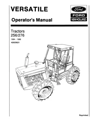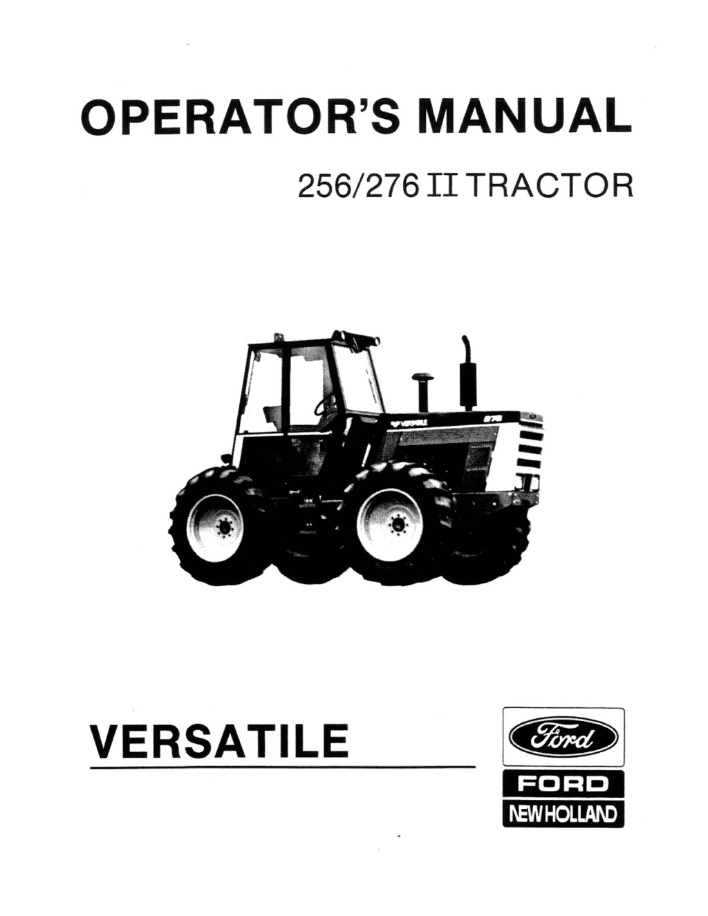
Versatile 256 276 II Tractor Operator’s Manual Instant Download (Publication No.42025620)
Please open the website below to get the complete manualnn//
Download Presentation

Please find below an Image/Link to download the presentation.
The content on the website is provided AS IS for your information and personal use only. It may not be sold, licensed, or shared on other websites without obtaining consent from the author. Download presentation by click this link. If you encounter any issues during the download, it is possible that the publisher has removed the file from their server.
E N D
Presentation Transcript
OPERATOR'S MANUAL 256/276 II TRACTOR l V_E_R_S_A_TI_L_E __ I~ FORD I\EW HOLLAI\D
WARRANTY VERSATILE PRODUCTS Ford New Holland, Inc. or New Holland of Canada Ltd., hereinafter called the "Company", warrants to each purchaser of farm equipment bearing the Versatile brand name from an authorized dealer that such equipment is free from defects in material and workmanship (except tires, tubes, and Cummins engines which are warranted as defined by the respective manufacturer) in accordance with the following provisions: All warranty periods begin with the date of first retail sale or first use, whether it be through rental, lease, or special demonstration program, whichever occurs first. This warranty is for the benefit of the original or subsequent purchaser during the remaining warranty period where the equipment is purchased from an authorized dealer of Versatile products. The warranty only applies if the equipment has been used and serviced in accordance with the recommendations in the Operator's Manual. The basic farm equipment warranty shall be 12 months. Specific tractor driveline components are extended to 24 months or 2,000 hours, whichever comes first. The obligation of the Company under this warranty is limited to repairing, or at its option replaCing any part(s} which, in the Company's judgment is defective. Except as set forth above, THE COMPANY SHALL HAVE NO OBLIGATION OR LIABILITY OF ANY KINO ON ACCOUNT OF ANY OF ITS EQUIPMENT . AND SHALL NOT BE LIABLE FOR SPECIAL OR CONSEQUENTIAL DAMAGES. THE COMPANY MAKES NO OTHER WARRANTY, EXPRESS OR IMPLIED, AND SPECIFICALLY, THE COMPANY DISCLAIMS ANY IMPLIED WARRANTY OF MERCHANTABILITY OR FITNESS. SOME STATES OR PROVINCES 00 NOT PERMIT LIMITATIONS OR EXCLUSIONS OF IMPLIED WARRANTIES OR INCIDENTAL OR CONSEQUENTIAL DAMAGES, SO THE LIMITATIONS OR EXCLUSIONS IN THIS WARRANTY MAY NOT APPLY. The specific details of the Owner's Warranty, outlined in more detail in "Warranty Detail" below are expressive of the quality built into your equipment. When you invested in this equipment, you became eligible for the protection of the Company's Warranty. WARRANTY DETAIL The following information explains the details of the Company warranty on Versatile products. Thase detaiis include an expianation of the criteria for determining warranty. those items covered by warranty, those not covered, and information on how to obtain warranty service. Items Not Covered 1. Dealer Travel Time - The customer shall be responsible for payment of dealer travet time to the machine or to deliver the machine to the dealer's service shop for repair. This warranty does not cover travel time. 2. Used Equipment - This warranty shall apply only to equipment sold by an authorized dealer. With the exception of special Extended Service Plans or other Owner Protection Programs, the Company shall have no liability for used equipment sold beyond the specified coverage period. All other used equipment is sold "AS IS". 3. Tires, Tubes - Tires and tubes shall be warranted by the respective manufacturers selling dealer or by local representatives of the manufacturer. 4. Modified or Altered Equipment - No warranty shall apply on any equipment or parts that have been modified, or altered in any way without prior approval and knowledge of the Company. Nor is there warranty if service, other than normal replacement of service items, is performed by someone other than an authorized deafer. 5. Normal Wear or Maintenance Parts - The Company shail not be responsible for normal replacement parts such as cutting knives. chains, belts, clutches, filters, oil, or other parts which are worn out. unless they are determined to be defective in material or workmanship. 6. Miscellaneous - No warranty shall apply to damage resulting from accident, misapplication. abuse, or damage caused by environment (such as exposure to corrosive material). The Company shall not be responsible for rental equipment used to replace the equipment being repaired, loss of time. or loss of use of product. or damage caused by improper servicing. Leased, Rented, or Special Purchase Plan When a unit is leased, rented or used by a customer on a Special Purchase Plan, the warranty period starts on the date the unit is first leased, rented. or otherwise put to use. If the unit is sold prior to the expiration of the warranty, the warranty will continue in effect for the remainder of the warranty period. About Improvements The Company is continually striving to improve its products, and therefore reserves the right to make improvements or changes when it becomes practical and possible to do so. Without incurring any obligations to make changes or additions to the equipment sold previously. Extended/LiriUIed Drivetrain Warranty In addition to the basic warranty, the following items are covered by an extended warranty to a maximum of 24 months or 2.000 hours, whichever comes first: - Hydrostatic Drive and Transmission case and all internal parts, transmission mounts, drivelines, and U-joints. - Axles, Differentials, dropbox housings and all internal parts. - Main Frame, Front and rear weldments. - Power Take-Off clutch, dropbox hOUSings and all internal parts, drivelines and U-joints. Warranty Determination Defective parts and the labor to replace same. are covered by this warranty. Any part or parts of a product found to be defective, will, in accordance with the provisions of this warranty. be repaired or replaced by an authorized dealer of Versatile products. Items Covered by Warranty This warranty includes the replacement or repair of any part or parts of machines or attachments on Versatile products purchased from an authorized dealer (except tires, and tubes, and Cummins engines) which are defective in material, workmanship. or both. Tires. tubes, and Cummins engines will be warranted as defined by their manufacturer. When premature part(s) failure can be attributed to normal use, and defective material or workmanship cannot be accurately defined, the allowance may be prorated according to the amount of use and known operating conditions. Genuine Versatile brand name replacement parts will be warranted for 90 days from date of purchase. or the remainder of the original equipment warranty period, whichever is longer. Obtaining Warranty Service To obtain warranty service. contact the authorized dealer from whom the machine was purChased. If this is not practical. any dealer authorized to sell Versatile products may perform warranty work, Engine warranty service shall be ha.ndled by the local Cummins dealer.
https://www.ebooklibonline.com Hello dear friend! Thank you very much for reading. Enter the link into your browser. The full manual is available for immediate download. https://www.ebooklibonline.com
OWNER ASSISTANCE We at Ford New Holland and your Ford New Holland dealer want you to be completely satisfied with your investment. Normally any problems with your equipment will be handled by your dealer's Service Department Sometimes, however, misunderstanding can occur. If your problem has not been handled to your satisfaction, we suggest the following. 1. Contact the owner or General Manager of the dealership, explain the problem. and request assistance. When additional assistance is needed, your dealer has direct access to our branch office. 2. If you cannot obtain satisfaction by doing this, contact the Ford New Holland branch office in your area and provide them with: Your name, address. and telephone number Machine model and serial number Dealership name and address Machine purchase date and amount of use Nature of problem New Holland 500 Diller Avenue New Holland, PA 17557 Telephone: (7i 7) 354':1112 Calgary Box 1616. Main P.O. Calgary. AB CANADA T2P 2M7 Telephone: (403) 273-6771 Toronto P.O. Box 7000 Brampton, ON CANADA l6V 2M9 Telephone: (416) 457 2720 Atlanta 2000 Mountain Ind, Blvd. Tucker, GA 30084 Telephone: (404) 491-3499 Oakland P.O. Box 12964 Oakland. CA 94604 Telephone: (415) 273-0200 Dallas P.O. BO")( 10227 Dallas, TX 75207 Telephone: (214) 939-4950 Kansas City P.O. Box 14550 lenexa, KS 66219 Telephone: (913) 888-7000 Minneapolis P.O. Box 1342 Minneapolis, MN 55440 Telephone: (612) 887-4232 Troy 1315 Coolidge Avenue Troy. MI 48084 Telephone: (313) 637-9382 3. If you need further assistance contact: Consumer Services Department Mail Station 500 Ford New Holland, Inc. New Holland, PA 17557 Telephone: (717) 354-1545 When contacting Ford New Holland's branch office or Consumer Services Department. be aware that your problem will likely be resolved in the dealership using the dealer's facilities, equipment, and personnel. So it is important that your initial contact be with the dealer.
Table of Contents 276 TRACTOR Operator'S Manual For Serial Numbers 332100 and ON 1 Safety ., ................. " ........................ " ...... Page 1 2 Controls and Instrumentation ................. Page 8 3 Operation ............................................. Page 15 4 Lubrication and Maintenance .............. Page 47 5 Troubleshooting .................................. Page 88 6 Storage ................................................. Page 93 7 Specifications and Schematics ............ Page 95 8 Index ................................................... Page 114 42025620 Replaces Versatile 108472 090087
Serial Number Location SERIAL NUMBER LOCATION IMPORTANT To obtain fastest service when ordering parts, Remember to: 1. Order part by the correct number. 2. State tractor mode! and year. 3. Include tractor, engine, transmission and frame serial numbers. TRACTOR ENGINE Serial number plate is located on engine left side ahead of fuel injection pump. Serial number plate is stamped on a metal tag on the steering console base right hand side. SERIAL ............................................................ . S,ERtAL No ....................................................... . Tractor Serial Number Plate Engine Serial Number Location ii
INTRODUCTION We are pleased you have chosen a VERSATILE Four Wheel Drive Tractor for your farming op- eration. It has evolved through the ideas and suggestions submitted to us by customers such as yourself. The suggested schedule has been designed to meet most operating conditions although it may be necessary to adjust your maintenance program to suit your specific operating condi- tions. Your Versatile dealer is factory trained to pro- vide you with genuine parts and professional repair service. Consult him for all your service needs. We ask that you study this manual and adopt the p,reventive maintenance program outlined in it. iii
aE ALERT Watch for this symbol. It identifies potential hazards to health or persona' safety. It pOints out safety precautions. It means: ATTENTION - Be Alert. Your safety is involved. Be ALERT BE ALERT BE ALERT BE ALERT iv
1 Safety National Safety Council statistics Indicate many people die or suffer serious Injury each year as a result of farm accidents. Don't become a statistic or victim. 7. Never jump from tractor. There is a danger of catching clothing on protruding parts. Carefully review the proce- ,....-------, dures g. iven in this manual with all operators ANNU- ALLY. It is important that all operators be familiar with, AND FOLLOW, safety prec- autions. 8. Use steps and handholds when mounting and dismounting tractor or for serVlcmg components too high to reach from the ground. 9. Fasten seat belt before starting engine. Operating instructions must be given to ev- eryone using the tractor before operation and at least once yearly thereafter in com- pliance with OSHA Regulation 1928.57 (United States). - 10. Safety devices are intended to protect op- erators from injury or death. Under no .cir- cumstances should they be disabled or removed. GENERAL SAFETY with ABC rating in the f Never let an unqualified or untrained driver operate tractor. 1. 11. To provide a better view, certain photos and illustrations show a safety shield re- moved. It is important that a machine never be operated in this way. Keep aU shields in place. Keep a fire extinguisher, 2. cab. Maintain it and be familiar with its use. OPERATING SAFETY Always operate tractor controls sitting in the operators seat 1. Never carry passengers. 3. Lock seat and instrument console in posi- tion and buckle seat belt before operating tractor. 2. Never operate tractor in a closed building. Provide adequate ventilation. ~ E n g i n e ex- haust fumes are poisonous and can kill. 4. Always start tractor with FNR (Propulslon)!ever in neutral, transmission in first range, PTO clutch lever(s) disengaged and other operating controls either in the OFF or neu- tral position. 3. Always keep sleeves, jackets or other clothing relatively tight and belted. Loose clothing may catch in moving parts and result In personal injury or death. 5. ,...-----.., Provide a first-aid kit in the cab for use in case of accident. 6. Safety 1
4. Always wait until all warning lights go out before putting tractor in gear. 5. Use caution when driving near the edge of' a ditch or gully. It may cave in, causing the tractor to roll over. 5. Never oil. grease or adjust tractor while it is running. Do not leave engine running while tractor or drawn equipment is being adjusted, repaired or cleaned. 6. Be especially alert when operating at rovv ends, road slopes and around ob- structions. 7. Slow down when turning corners, the dan- ger of tipping increases. 00 not travel at: high speeds. 6. Ensure parkbrake is set when tractor is stopped. Tractor can freewheel even when in gear. 7. Avoid abrupt turns, starts or stops, espe- cially at high speeds. MAINTENANCE SAFETY 1. Escaping hydraulic oil under pressure can pen- ~ etrate the skin causing personal injury. Wear gloves and goggles and use a piece of cardboard or wood as a backstop '-_____ for spurting fluid when searching for hy- draulic leaks. 8. Keep all safety shields in place when op- erating tractor. JC' . . 9. Do not operate tractor when you are tired, sick or impaired. -l 10. Never operate tractor in confined areas. Visabity next to tractor is reduced. Injury to bystanders or damage to tractor or equipement may result. 2. Ensure all connections are tight and lines and hoses are undamaged. Before dis- connecting hydraulic lines. relieve all- pressure. Do not overfill tank. 11. 00 not start engine by shorting across starter terminals. Engine can start and machine can move when starting safety switch is bypassed. 3. Add coolant to the cooling system only when engine is stopped and cool. Turn ra- diator cap slightly to its first stop to relieve pressure before remOVing. SAFE OPERATION IN ROUGH TERRAIN 4. Never when engine is hot or running. Do not smoke while filling fuel tank or servicing fuel system. Use precautions in han- dling any type of tractor fuel. Vapourized diesel fuel is highly flammable. overfill. refuel tractor 1. Drive tractor slowly on hillsides and curves to eliminate the danger of tipping. Avoid slopes which are too steep for safe operation. Avoid sharp uphill turns. Do not Ground fuel storage tanks to prevent stati c buifdup. 5. 2. Always drive slowly over rough ground. Drive at speeds slow enough to ensure your safety. 6. 00 not smoke and avoid open flames if servicing any batteries. 3. When driving out of a ditch, gully or up a steep hillside, engage the transmission drive slowly. Avoid sharp uphill turns. 7. Starting fluid is highly flammable. Do not use near fire, sparks, open flames or when engine is running. 4. When descending steep grades, select a sufficiently slow speed to maintain control with minimum braking. 8. Remove mUd, crop residue, chains and tools from steps and operator's platform. 2 Safety
2, Ensure articulation lock wl set and gearshift lever is in neutral when using PTO in stationary appli- cations. Do not leave tractor unattended. If you must leave the area for any reason, stop tractor and re- move key. They may interfere with pedal operation or entry/exit from tractor. POWER TAKE-OFF (PTO) SAFETY 1. Never start tractor with PTO engaged. Engage safety locks or block implements when servicing. 9. is engaged. parkbrake is 10. Ensure turbocharger is cool before servic- ing and keep flammable material away from turbocharger. 11. Never operate with a damaged tire. Tire may explode. 3. Take special care in hook-up of imple- ments to PTO. IMPLEMENT SAFETY Always hitch loads to drawbar or hitch points. 1, Ensure all guards are in place while oper- ating PTO. 4. 5. Stop tractor before disconnecting or ser- vicing PTO drivelines. 2. When drawbar, only allow assistant between tractor and implement if the tractor is in neutral and the brakes are engaged. hitching drawn equipment to SAFE HIGHWAY OPERATION 3. When implement is not in use' or being disconnected from the tractor, always r e ~ lieve p r e ~ s u r e from hydraulic circuits. In- stall safety locks or pins to prevent implement movement. 1. Before transporting tractor and/or imple- ments on public roadways check with au thorlties for local regulations. Drive tractor In engine forward configura- tion only when driving on roads or trans- porting implements. 2. Do not leave implements with hydraulic cylinders fully extended or retracted were the heat from the sun can cause the hy- draulic fluid to expand. Hydraulic pressure can rupture hoses, releasing high pres- sure oil causing personal injury. 4. Equip tractor and towed implements with slow moving vehicle (SMV) signs when travelling on public roads. 3. 8e careful when turning with a implement Lift it from the ground if possible during turns. Side thrust caused by implement could damage tire and implement. 5. Install additional lights on implement rear to safeguard against rear end collisions. Daybreak and dusk are particularly dan- gerous. VERSATILE seven-pin trailer connectors to facilitate installation of extra lighting. 4. tractors have Use transport locks, lower implement to ground and securely block frame before servicing Implement. Relieve pressure from the hydraulic system and shut off tractor. 6. 5. 8e aware of transport width of towed im- plements. Install additional lights to left side of wide implements to alert passing traffic. Keep clear of the. approaching lane. 6. Use hazard warning flashers as required by law when transporting or driving tractor on public roads. Safety 3
7. Keep to the right and yield right-at-way especially when pulling implements. Pull off road and stop to allow motorists to pass. Drive on the road shoulder, it per- mitted by law. less articulation lock and parkbrake are engaged. Use extreme caution when pulling heavy loads at road speeds. Avoid hard applica- tion of tractor brakes at high speed. Equip implement trailers with brakes as required by law. 8. 9. Ensure headlights are aligned so they will not blind the operators of oncoming vehi- cles. CHEMICAL SAFETY Articulation Lock 1. The cab air tilters are not designed to filter harmful chemicals. When using agricul- tural chemicals. follow the manufacturer's instructions carefully. ALTERNATE EXITS The cab has three exits which may be used in an emergency; the two doors and the rear window. Rear Window Open the rear window by unlocking the two latches. Push window open at bottom. 2. 00 nj2,t carrY harmful chemicals in the cab. Chemicals may rupture the container and the fumes may poison the operator. , ~ ~ POISON 3. Wear approved respiratory protection when working near toxic chemicals. Main- tain equipment regularly. ARTICULATION LOCK 1. Use articulation lock during stationary ap- plications, servicing, jacking or overhaul operations. 00 not use when tractor is op- erating. 2. Before engaging lock, drive tractor to a level surface, put steering straight, engage parkbrake, put FNR Lever in neutral and stop engine. Alternate Exit, Rear Window LOADER SAFETY Refer to Loader Operators Manual for further instructions 3. Remove arm from storage position on front frame and put through hole on rear frame. It may be necessary to start engine and articulate frame slightly to ensure arm is engaged. Secure with klik pin. 1. Improper use of loader or attachments can cause serious injury or death. 2. Operate all controls from operator's seat. Before starting engine, fasten seat belt and put all controls in neutral. 4. Do not allow personnel to enter artic- ulation area with the engine running, un- 4 Safety
12. Confine operation to solid ground. Loader operation around loose fill, rocks and holes is dangerous. 3. Be famiUar with hydraulic controls and d i ~ rection of operation. 4. Back down ramps and slopes keeping bucket low for added stability. Be extra careful on inclines. 13. Allow for loader length when making turns. Set wheels at widest convenient spacing for stability and add recommended ballast to engine end tires. 5. Never allow people to ride in bucket 14. Avoid overhead powerlines when loader is raised. 6. Do not hook a chain to bucket to pull or pry. 15. When removing loader from tractor park on a hard level surface. 7. Lower bucket to ground when leaving ma- chine for any reason. Do not walk or work under a raised bucket. SAFETY DeCALS 8. Reduce ground speed when earring loads and while turning. Carry loads within 600 mm (24 in.) of the ground. cloth when necessary. A 1. Keep decals clean. Re- move dirt with a wet 9. Carry loads within 600 mm (24 in.) of ground except when dumping. sharp. high speed turns with full bucket Use caution when handling loose or shiftable loads. Avoid BE ALERT 2. Replace safety decals if destroyed, miss- ing, painted over or unreadable. 3. If a section of the tractor is replaced that carries a safety decal, apply a new decal immediately. 10. Nevg wallCor work beneath raised bucket. 11. Never operate loader with frayed or dam- aged hoses or leaking fittings. Before dis- connecting lines, relieve all pressure. 4. New decals are available from your Ver- satile dealer. Safety 5
SAFETY DECALS 4 3 9 7 p!III!p.-----..... ACAUTION 1 0 " ' - ~ - - - - - . A CAUTION IMPORTANT l Opemill9 iJlSlrllCfI.A. mU$1 be gi' _ to mII'YO'M usin, tm. 'ItlIIltot It die time of InitW _DiUmnent allll tlNat 1I1l_tly tMrnft in fCconl.au wit" OSHA rqalatioe 1928'51 & 111%1-51 KEEP AU. SAFETY SHIELDS IN PLACE WHEN OPERATING MACHINE SEAT ROTATION LOCK SLIDE SEAT FULLY FOR WARD AND PULL OUT LOCK FOR ROTATION. EN- SURE LOCK IS ENGAGED BEFORE START!NG ENGINE. "':::4$ MAC 00 Oft'UfQlUATMS MItMW.. t J 6 ~ YlQ[O WITM -nJ1$ Wtfctl nculI{U' fASnftlOUii surtEtl *It mtl f V l l f i ' O ~ U !scUAt!: Of MtiCMlffEtJ ,nOI( stunK Nt l"*' OR OHU' .,. TMf ""in.I. ~ a ,ossm:u. *-YOID OfIEA4l'mG fMf lW "Tat .tAft ClTtH!$. fM,M U!TS fM MOtts fliUNCl S1t(D \ft.!. fUiUti_ (ROUl'*" SlOPE" DO. acrumt sua, a:a MUOIn' SUR ~ ...... .$fl.'" Of-f S\.OP $ tOtl!tUP: f(pi SAIl mu- to .. WATt" dOl rou . ~ f tiOfl!J', UPtCiAUf 41' MW UJOS . .ow lOMJ$, IttiO AfI(lUHO ~ 00 m ,. jllT OfHtl" tll ittO Ii,-{AATt rWE nu.t;:TOR SMOO'Ttfl'l - tiS Jt:Mtf $tUn., lUP/.I. M sro"" ItfftM lUlU' "TO 1M.' nuwtA" OQ TN"! ( ~ IOTU(fW$Utf1 .. WJlue: tMC'tQfI !$ STOfl1'Uf iU MAI'UIitG aWl: uenuY: ne, AU ~ v A A O $ UJ 9l4C1 MIEN MACK!.! I$; IMott:U TiO. $' UNW" NtG wAiT f<Uli .iU MACH"E IWOVtIlftIT l'O-SfM Ilynt IttVtCUtG.:UD " ~ . 01 AO.NSlI.'. 78102 9 ................ . 11--------- A WARNING Ave,o POSS.ala INJURY OR DEAn. FI10M A MA.CrHNE RUNAWAY Dc ~ Q ~ $;t3{t tH'i'lfltl# 1)): ~ ~ r \ B ' ' \ 1 ; acr -;t$ ~ h u ' ! ~ t j"Umltlit!$ E ( t ~ ~ M tat'! $tiU'l ~ m $ C l " d ~ t < mo't!!' ' < ' i i~ $la.rto InIJ ' i t e t I)'m&M I H S toe. Mil$T 51: IS;mMt.u;g 3(t"ORi Stp;VtCHIlC AA"hCVI..A:TU;)1i A$lEA .140 tH,nm"U $1'AnQM"",. "'0 . , " ~ o o r o N a l()CK MtJ5T 1 mSOHlAGE"D !lI'OA,f;\: 1II000NG TAAClmt $taort & n 9 ~ t \ $ o<"<ly t ~ ~ Op.e}'rMOf't S!!!$t w ~ l n H,**$< ~ ~ _ t r ' H & ~ , : : : : > t ' ; !" M\tIf8! ' .aM P l l r X b t ~ 1 I . $ ~ i ~ . ' f ~ i W \ { c ! l t S . 1 2 ~ " " " " " " " " " . ACAUTION SELECTOR SWITCH MUST BE IN MANUAL MODE WHEN TRANS- PORTING THREE POINT HITCH MOUNTED 1M PLEMENTS. 6 Safety
SAFETY DeCALS 3 4 S " ' A ~ C - A U - ' -N .... 1 .............. ACAUTION . TIllS SHIELD HAS BEEN INSTAllHI FOR YOUR PROTECTION DO NOT REMOVE WHEN P.T.IlIS NOT IN USE PlACE Foro. CONTROl. I.EV R IN NEUTRAL POSITION OPERATE DillY WITH 540 /l1t.1. EOUIPIEHT ,.", .............. A WARNING _ 3 ~ ALWAYS FASTEN SEAT BELTS WHEN OPERATING TRAefOR EQUIPPEO WITH ROLL OVER PROTECTIVE STRUCTURE. ARTICULATING JOINT, STAY CLEAR OF THIS WHEN ENGINE IS RUNNING. THIS ROll OVER PRO- TECTIVE STRUCTURE DESIGN MEETS OSHA PERFORMANCE CRITERIA WHEN INSTAllEO IN ACCORDANCE WITH VERSATILE FARM EQUIP- MENT COMPANY MOUNT- ING INSTRUCTIONS. AREA 6,.------. ACAUTION THE PROTECTION AF- FORDEO MAY BE IMPAIR- EO IF IT HAS HEN SUIJ.. JECTeo TO ALTERATION, STRUCTURAL DAMAGE OR INVOLVED IN AN OVER- TURN ACCIDENT. IN THESE CASES THE EN- TIRE STRUCTURE MUST BE R E P I . A ~ O . ATTACHMENT SAFETY GUIDES READ AND OBSERVE SAFETY RECOMMENDA. TIONS IN ATTACHMENT OPERATOR'S MANUAL MOVE AND TURN TRAC TOil AT l.OW SPEEDS. CARRY ATTACHMENT AT LOW POSITION DURING TRANSPORT. lOWER ATTACHMENT, STOP ENGINE AND APPt. y PARKBRAKE BEFORE LEAVING OPERATOR'S SEAT. KEEP AWAY FROM OVERHEAD ELECTRIC WIRES. ELECTROCUTION MAY RESULT. STANO OR WORK A RAISED ATTACH - - - - - - - - - - - - - - ~ A CAUTI ON WATCHVOUR STEP 4 .. 2.--------------. A WARNING OISENGAGE P,T.O. CWTCH 4NO STOP ENGINE 8EfOIl LEAVING OPEIIATOR'S STATION. NEVER SERVICE. AOJUST. CONNECT 011 UNCLOG P.'tO. OlliveN EQUIP- MENT WHILE ENGINE IS RUNNIIiG. ADO BALLAST TO ENGINE END TIRES FOR MAXIMUM STABILITY. (SEE OPERATOR'S MANUAL). SEE OPERATOR'S MANUAL FOR RECOMMENDED WHEEL SPACING. 91868 Safety 7
HYDRAUtlC OETENT CONTROL LEVER HYDRAULIC FLOAT CONTROL PEDAL STANDARD HYORAULIC CONTROL PEDAL Cab Controls (Engine Forward Configuration) 8 Controls and Instrumentation
2 CONTROLS AND INSTRUMENTATION IMPORTANT The following section locates, identifies and briefly describes the functions of all cab controls. All operators should familarize themselves with control location and function prior to machine operation. Failure to do so may result in unsafe operation of the machine and possible injury or death to operators and bystanders. INSTRUMENT PANEL Off: Engine and electrical functions remain OFF. Run: Turns the electrical system ON and is normal operating position. Start: Cranks engine. Release key to return to Run position. ENGINE COOLANT ~ TEMPERATURE GAUGE ~ ~ Indicator lights Parkbrake: Illuminates when parkbrake is ON. Engine Oil Pressure: Illuminates when pressure drops below 83 kPa (12 psi). Air Cleaner: Illuminates when filter is clogged. Alternator: Illuminates when alternator is not charging. High Beam: Illuminates when high beam work lamps are ON. Hazard: Illuminates when hazard warning lights are ON. fUEL GAUGE COLO START sunOH Instrument Panel Gauges Fuel Gauge: Indicates fuel level. Engine Coolant Temperature Gauge: Indicates engine coolant temperature in C and 0 F. Normal operating temperature is 85 C (185 F). Keyswltch The keyswitch has four positions. Accessory: Electrical accessories can be used when en- gine is not running. Push key IN and turn key to the left. Controls and Instrumentation 9
Cold Start Sutton Use to inject starting fluid below 100e (50 F). ~ Use the depth control knob to set implement working depth for use in the automatic mode. Turn knob clockwise counter-clockwise to lower. Turning knob fully counter-clockwise will set depth control to FLOAT so hitch follows ground contours. Lowering Rate: Controls hitch lowering rate in relation to im- plement weight. Tum knob clockwise to in- crease lowering rate; counter-clockwise to decrease lowering rate. The raise rate is a d justed with a flow control on the implement hydraulic valve. Up/Down Switch: Manual Operation Press UP to raise and DOWN to lower hitch when in manual. Release switch when desired position is reached. Push switch momentarily to fine adjust hitch position. Auto Operation Pressing AUTO will put the hitch into automatic mode. The hitch will automatically adjust depth to the position as defined by the operator with the DEPTH control knob. maintained automatically. Pressing UP will raise the three-point hitch to the highest position for transport or turning corners. Pressing DOWN will return the three-point hitch to the preset depth. Rear Hitch Switch: Located on FNR control le- ver Front Hitch Switch: Located on side console Speedometer/Tachometer/Hour Meter: to raise and Rocker Switch: Two position switch used to select between speedometer and tachometer settings. Speedometer: Indicates ground speed. calculated from the engine r/min. Inner scale indicates miles per hour (MPH). The outer scale indicates kilome- ters per hour (KMH), the outer scale is also used for engine r/min. Tachometer: Indicates engine speed from idle (1 000 r/min) to full engine speed (2 500 r/min). This the outer scale of the meter. Hourmeter; Indicates total hours the engine has run, oper- ates only when the engine is running. ~ CAS LEF-k HANn SIDE CONSOLE Forward-Neutral-Reverse Lever (FNR): Push neutral lock release down and push lever forward or pull back in the desired direction of travel. The further the lever is moved from neutral the faster the ground speed. The position is PTO Clutch Control: Move lever toward door to engage; away to disengage. Ensure engaged/disengaged. Engine can only be started with clutch disengaged. Controls en- gagement of both front and rear PTO. is lever fully Cigar Lighter Push Down to heat element Pops up when ready Front and Rear PTO Control Knobs: Pull knob(s) up to engage; push down to dis- engage. Ensure engaged/disengaged. Knobs are only present with front PTO option. Standard Hydraulic Lever (Green) Three positions: Raise, Lower and Neutral. Lever spring centred to neutral. Push lever away from operator to lower implement, to ward to raise. Release lever to return to neu- tral. Lever and adjacent foot pedal work together. clutch is fully Three Point Hitch Controls Front and Rear Hitch Auto/Manual: Press rocker switch to select mode. 10 Controls and Instrumentation
Suggest: If the above button click is invalid. Please download this document first, and then click the above link to download the complete manual. Thank you so much for reading
Indicator lamps Indicates hazard lamps and turn Signals are functioning. Turn Signal Switch Three pOSition switch: Centre: Both Hazard lamps and indicator lamps. Right: Right Hazard Lamp and indicator lamp. Left: Left Ha. zard lamp and indicator lamp. Light switch must be in positions 2, 3 or 4 for turn signals to function. .NlIlEVER ~ ~ # ' ~ g ~ R O C i ( S H A F T F I' ., Auxiliary Light Switch Controls auxiliary work lamps. ~ I~ ~ O S I T I O N CONTROL High/Low Beam Switch Controls high/low beam on engine end road lamps. THIIEE,POINT HITCH FLOW CONTROL Range Control Provides three ranges, neutral positon be- tween first and second and second and third ranges. Cab L.eft Hand Stde Console CAB RIGHT"'SIOe- Throttle Depress button and pull knob UP to increase engine speed; depress button and push knob DOWN to decrease. Detent Hydraulic Lever (Blue) Three positions: Raise, Lower and Neutral. Lever spring centred to neutral, locks in detent in raise and lower positions. Lever will self cancel to neutral when pressure exceeds de- tent setting. Push lever away from operator to lower implement, toward to raise. Release le- ver to return to neutral. Lever and outer foot pedal work together. L.ight/Hazard Switch Controls lights on the tractor. Five position rotary switch: 1. OFF Float Hydraulic Lever (Tan) Four positions: Raise, Lower. Float and Neu- tral. Lever spring centred to neutral, locks tn detent in float pOSition if Lever is pushed be- yond lower position. Lever can be moved from float to lower at any time. Push lever away from operator to lower implement, toward to raise. Release lever to return to neutral. Lever and inner foot pedal work together. 2. Hazard warning lights and dash lights. 3. Hazard taillights (high/low beams). warning (RED). lights, engine dash end lights, lamps Hazard lights,taillights (RED), engine end road lamps (high/low beams) and rear work lights. warning lights, dash 4. Flow Contro' (Blue) Flow control lever adjusts flow to hydraulic circuit for blue lever. Push away from operator to increase flow; pull toward to decrease flow. The other circuits are adjusted at the imple- ment valve. Dash lights, engine end road lamps (high/low beams), rear work lights. 5 ~ Controls and Instrumentation 11
https://www.ebooklibonline.com Hello dear friend! Thank you very much for reading. Enter the link into your browser. The full manual is available for immediate download. https://www.ebooklibonline.com

