Understanding Memory Consistency Models and Communication Paradigms in Computer Systems
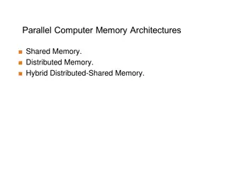
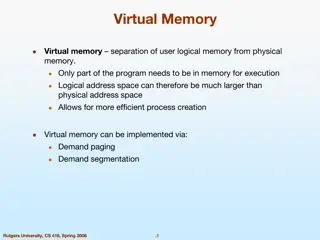
Memory consistency models define the ordering of writes and reads in computer systems. Coherence ensures write propagation and serialization, while consistency models guide programmers in writing correct programs. Shared-memory and message-passing are two communication paradigms with different approaches to handling data transfer and caching.

Download Presentation

Please find below an Image/Link to download the presentation.
The content on the website is provided AS IS for your information and personal use only. It may not be sold, licensed, or shared on other websites without obtaining consent from the author. Download presentation by click this link. If you encounter any issues during the download, it is possible that the publisher has removed the file from their server.
E N D
Presentation Transcript
Lecture 27: Pot-Pourri Today s topics: Consistency Models Shared memory vs message-passing Simultaneous multi-threading (SMT) GPUs Accelerators Disks and reliability 1
Coherence Vs. Consistency Recall that coherence guarantees (i) write propagation (a write will eventually be seen by other processors), and (ii) write serialization (all processors see writes to the same location in the same order) The consistency model defines the ordering of writes and reads to different memory locations the hardware guarantees a certain consistency model and the programmer attempts to write correct programs with those assumptions 2
Consistency Example Consider a multiprocessor with bus-based snooping cache coherence Initially A = B = 0 P1 P2 A 1 B 1 if (B == 0) if (A == 0) Crit.Section Crit.Section 3
Consistency Example Consider a multiprocessor with bus-based snooping cache coherence Initially A = B = 0 P1 P2 A 1 B 1 if (B == 0) if (A == 0) Crit.Section Crit.Section The programmer expected the above code to implement a lock because of ooo, both processors can enter the critical section The consistency model lets the programmer know what assumptions they can make about the hardware s reordering capabilities 4
Sequential Consistency A multiprocessor is sequentially consistent if the result of the execution is achieveable by maintaining program order within a processor and interleaving accesses by different processors in an arbitrary fashion The multiprocessor in the previous example is not sequentially consistent Can implement sequential consistency by requiring the following: program order, write serialization, everyone has seen an update before a value is read very intuitive for the programmer, but extremely slow 5
Shared-Memory Vs. Message-Passing Shared-memory: Well-understood programming model Communication is implicit and hardware handles protection Hardware-controlled caching Message-passing: No cache coherence simpler hardware Explicit communication easier for the programmer to restructure code Software-controlled caching Sender can initiate data transfer 6
Ocean Kernel .. Procedure Solve(A) begin diff = done = 0; while (!done) do diff = 0; for i 1 to n do for j 1 to n do temp = A[i,j]; A[i,j] 0.2 * (A[i,j] + neighbors); diff += abs(A[i,j] temp); end for end for if (diff < TOL) then done = 1; end while end procedure Row 1 Row k Row 2k Row 3k 7
Shared Address Space Model procedure Solve(A) int i, j, pid, done=0; float temp, mydiff=0; int mymin = 1 + (pid * n/procs); int mymax = mymin + n/nprocs -1; while (!done) do mydiff = diff = 0; BARRIER(bar1,nprocs); for i mymin to mymax for j 1 to n do endfor endfor LOCK(diff_lock); diff += mydiff; UNLOCK(diff_lock); BARRIER (bar1, nprocs); if (diff < TOL) then done = 1; BARRIER (bar1, nprocs); endwhile int n, nprocs; float **A, diff; LOCKDEC(diff_lock); BARDEC(bar1); main() begin read(n); read(nprocs); A G_MALLOC(); initialize (A); CREATE (nprocs,Solve,A); WAIT_FOR_END (nprocs); end main 8
Message Passing Model main() read(n); read(nprocs); CREATE (nprocs-1, Solve); Solve(); WAIT_FOR_END (nprocs-1); for i 1 to nn do for j 1 to n do endfor endfor if (pid != 0) SEND(mydiff, 1, 0, DIFF); RECEIVE(done, 1, 0, DONE); else for i 1 to nprocs-1 do RECEIVE(tempdiff, 1, *, DIFF); mydiff += tempdiff; endfor if (mydiff < TOL) done = 1; for i 1 to nprocs-1 do SEND(done, 1, I, DONE); endfor endif endwhile procedure Solve() int i, j, pid, nn = n/nprocs, done=0; float temp, tempdiff, mydiff = 0; myA malloc( ) initialize(myA); while (!done) do mydiff = 0; if (pid != 0) SEND(&myA[1,0], n, pid-1, ROW); if (pid != nprocs-1) SEND(&myA[nn,0], n, pid+1, ROW); if (pid != 0) RECEIVE(&myA[0,0], n, pid-1, ROW); if (pid != nprocs-1) RECEIVE(&myA[nn+1,0], n, pid+1, ROW); 9
Multithreading Within a Processor Until now, we have executed multiple threads of an application on different processors can multiple threads execute concurrently on the same processor? Why is this desireable? inexpensive one CPU, no external interconnects no remote or coherence misses (more capacity misses) Why does this make sense? most processors can t find enough work peak IPC is 6, average IPC is 1.5! threads can share resources we can increase threads without a corresponding linear increase in area 10
How are Resources Shared? Each box represents an issue slot for a functional unit. Peak thruput is 4 IPC. Thread 1 Thread 2 Thread 3 Thread 4 Idle Cycles Superscalar Fine-Grained Multithreading Simultaneous Multithreading Superscalar processor has high under-utilization not enough work every cycle, especially when there is a cache miss Fine-grained multithreading can only issue instructions from a single thread in a cycle can not find max work every cycle, but cache misses can be tolerated Simultaneous multithreading can issue instructions from any thread every cycle has the highest probability of finding work for every issue slot 11
Performance Implications of SMT Single thread performance is likely to go down (caches, branch predictors, registers, etc. are shared) this effect can be mitigated by trying to prioritize one thread With eight threads in a processor with many resources, SMT yields throughput improvements of roughly 2-4 12
SIMD Processors Single instruction, multiple data Such processors offer energy efficiency because a single instruction fetch can trigger many data operations Such data parallelism may be useful for many image/sound and numerical applications 13
GPUs Initially developed as graphics accelerators; now viewed as one of the densest compute engines available Many on-going efforts to run non-graphics workloads on GPUs, i.e., use them as general-purpose GPUs or GPGPUs C/C++ based programming platforms enable wider use of GPGPUs CUDA from NVidia and OpenCL from an industry consortium A heterogeneous system has a regular host CPU and a GPU that handles (say) CUDA code (they can both be on the same chip) 14
The GPU Architecture SIMT single instruction, multiple thread; a GPU has many SIMT cores A large data-parallel operation is partitioned into many thread blocks (one per SIMT core); a thread block is partitioned into many warps (one warp running at a time in the SIMT core); a warp is partitioned across many in-order pipelines (each is called a SIMD lane) A SIMT core can have multiple active warps at a time, i.e., the SIMT core stores the registers for each warp; warps can be context-switched at low cost; a warp scheduler keeps track of runnable warps and schedules a new warp if the currently running warp stalls 15
Architecture Features Simple in-order pipelines that rely on thread-level parallelism to hide long latencies Many registers (~1K) per in-order pipeline (lane) to support many active warps When a branch is encountered, some of the lanes proceed along the then case depending on their data values; later, the other lanes evaluate the else case; a branch cuts the data-level parallelism by half (branch divergence) When a load/store is encountered, the requests from all lanes are coalesced into a few 128B cache line requests; each request may return at a different time (mem divergence) 17
GPU Memory Hierarchy Each SIMT core has a private L1 cache (shared by the warps on that core) A large L2 is shared by all SIMT cores; each L2 bank services a subset of all addresses Each L2 partition is connected to its own memory controller and memory channel The GDDR5 memory system runs at higher frequencies, and uses chips with more banks, wide IO, and better power delivery networks A portion of GDDR5 memory is private to the GPU and the rest is accessible to the host CPU (the GPU performs copies) 18
Tesla FSD 19 Image Source: Tesla
Role of Disks Activities external to the CPU/memory are typically orders of magnitude slower Example: while CPU performance has improved by 50% per year, disk latencies have improved by 10% every year Typical strategy on I/O: switch contexts and work on something else Other metrics, such as bandwidth, reliability, availability, and capacity, often receive more attention than performance 20
Magnetic Disks A magnetic disk consists of 1-12 platters (metal or glass disk covered with magnetic recording material on both sides), with diameters between 1-3.5 inches Each platter is comprised of concentric tracks (5-30K) and each track is divided into sectors (100 500 per track, each about 512 bytes) A movable arm holds the read/write heads for each disk surface and moves them all in tandem a cylinder of data is accessible at a time 21
Disk Latency To read/write data, the arm has to be placed on the correct track this seek time usually takes 5 to 12 ms on average can take less if there is spatial locality Rotational latency is the time taken to rotate the correct sector under the head average is typically more than 2 ms (15,000 RPM) Transfer time is the time taken to transfer a block of bits out of the disk and is typically 3 65 MB/second A disk controller maintains a disk cache (spatial locality can be exploited) and sets up the transfer on the bus (controller overhead) 22
Defining Reliability and Availability A system toggles between Service accomplishment: service matches specifications Service interruption: service deviates from specs The toggle is caused by failures and restorations Reliability measures continuous service accomplishment and is usually expressed as mean time to failure (MTTF) Availability measures fraction of time that service matches specifications, expressed as MTTF / (MTTF + MTTR) 23
RAID Reliability and availability are important metrics for disks RAID: redundant array of inexpensive (independent) disks Redundancy can deal with one or more failures Each sector of a disk records check information that allows it to determine if the disk has an error or not (in other words, redundancy already exists within a disk) When the disk read flags an error, we turn elsewhere for correct data 24
RAID 0 and RAID 1 RAID 0 has no additional redundancy (misnomer) it uses an array of disks and stripes (interleaves) data across the arrays to improve parallelism and throughput RAID 1 mirrors or shadows every disk every write happens to two disks Reads to the mirror may happen only when the primary disk fails or, you may try to read both together and the quicker response is accepted Expensive solution: high reliability at twice the cost 25
RAID 3 Data is bit-interleaved across several disks and a separate disk maintains parity information for a set of bits For example: with 8 disks, bit 0 is in disk-0, bit 1 is in disk-1, , bit 7 is in disk-7; disk-8 maintains parity for all 8 bits For any read, 8 disks must be accessed (as we usually read more than a byte at a time) and for any write, 9 disks must be accessed as parity has to be re-calculated High throughput for a single request, low cost for redundancy (overhead: 12.5%), low task-level parallelism 26
RAID 4 and RAID 5 Data is block interleaved this allows us to get all our data from a single disk on a read in case of a disk error, read all 9 disks Block interleaving reduces thruput for a single request (as only a single disk drive is servicing the request), but improves task-level parallelism as other disk drives are free to service other requests On a write, we access the disk that stores the data and the parity disk parity information can be updated simply by checking if the new data differs from the old data 27
RAID 5 If we have a single disk for parity, multiple writes can not happen in parallel (as all writes must update parity info) RAID 5 distributes the parity block to allow simultaneous writes 28
RAID Summary RAID 1-5 can tolerate a single fault mirroring (RAID 1) has a 100% overhead, while parity (RAID 3, 4, 5) has modest overhead Can tolerate multiple faults by having multiple check functions each additional check can cost an additional disk (RAID 6) RAID 6 and RAID 2 (memory-style ECC) are not commercially employed 29
Memory Protection Most common approach: SECDED single error correction, double error detection an 8-bit code for every 64-bit word -- can correct a single error in any 64-bit word also used in caches Extends a 64-bit memory channel to a 72-bit channel and requires ECC DIMMs (e.g., a word is fetched from 9 chips instead of 8) Chipkill is a form of error protection where failures in an entire memory chip can be corrected 30
Computation Errors TMR Errors in ALUs and cores are typically handled by performing the computation n times and voting for the correct answer n=3 is common and is referred to as triple modular redundancy 31