Understanding Magnetic Disks and Disk Controllers in Computer Memory Hierarchy
Auxiliary memory in computer systems provides additional backup storage through technologies like magnetic disks and tapes. Magnetic disks, which consist of circular platters coated with magnetizable material, offer direct access storage and are controlled by read/write mechanisms and disk controllers. The inclusive write/magnetoresistive read head technology enhances storage density and speed. Understanding the functions and mechanisms of magnetic disks is essential for efficient data storage and retrieval in computer memory systems.
Download Presentation

Please find below an Image/Link to download the presentation.
The content on the website is provided AS IS for your information and personal use only. It may not be sold, licensed, or shared on other websites without obtaining consent from the author. Download presentation by click this link. If you encounter any issues during the download, it is possible that the publisher has removed the file from their server.
E N D
Presentation Transcript
Memory. . . Presented By Ravindra Singh Rajput Asst. Professor Computer Dept Durga Mahavidyalaya Raipur(CG) 1
What is Auxiliary Memory? Auxiliary memory provides extra backup storage. For example: magnetic disks, magnetic tapes. Used to overcome the limitations of primary storage. Unlimited capacity because the cost per bit of storage is very low. Larger capacity than main memory. Used to store large volumes of data on a permanent basis. It is Non-volatile in nature. It is also known as Secondary Memory.
Magnetic Disks A disk is a circular platter constructed on non-magnetic material, called the substrate, coated with a magnetizable material like iron oxide particles are magnetized to store data. Read/Write data from/to its surface on platters. Surface divided into tracks and sectors. Support direct access mechanism. Has a disk controller and read/write head. Substrate used of aluminum. Nowadays, glass is used to improve magnetic film surface uniformity, thus reliability and to reduction in surface defects, helps to reduce read/write errors.
Magnetic Disk - Write Mechanism Data recorded and retrieve via a conductive coil, called a head. Head consists of a core with an air gap and a set of coils. May be separate read and write head. During read/write, the head is stationary and the plotter rotates beneath it. For writing data onto the medium, the data is converted into current and it passed through the read/write head coil. This generates a magnetic flux. This magnetic flux is used to magnetize the particles on the surface.
Inclusive Write/Magnetoresistive Read Head
Magnetic Disk - Read Mechanism During the read operation, when the flux transition pass under a head gap, a voltage is introduced in the read/write coils. This voltage is converted into the data pulses. New method: Separate read head positioned close to write head for convenience. Read head consists of a partially magnetoresistive (MR) sensor. MR material has an electrical resistance, which depends on the direction of magnetic field moving under it. By passing current through MR sensor, resistance changes are detected as voltage levels. Allows greater storage density, high frequency operation and high speeds.
Functions Disk Controller To interface a disk disk to the CPU. Disk drive selection, in case of multiple disks. Track and sector selection. To issue commands to the disk drive system to perform read/write operations. Error detection.
Disk organization and formatting Concentric Rings or tracks. Each track has the width same as of disk head. Tracks separated by gaps, minimizes errors in case of interference or head misalignment. Tracks divided into sectors- pie shaped segment, data transferred to and from the disk sector. Minimum block size is one sector; 512 bytes in most systems. May have more than one sector per block.
Disk Velocity Bit near center of rotating disk passes fixed point slower than bit on outside of disk. Increase spacing between bits in different tracks. Rotate disk at constant angular velocity (CAV) Gives pie shaped sectors and concentric tracks. Individual tracks and sectors addressable. Move head to given tracks and wait for given sector. Waste of space on outer tracks Lower data density. Can use zones to increase capacity Each zone has fixed bits per track More complex circuitry.
Multiple Platter One head per side. Heads are joined and aligned Aligned tracks on each platter from cylinder. Data is striped by cylinder Reduce head movement. Increases speed (transfer rate). Cylinder- Set of all tracks in same relative position on the platter.
Types of Magnetic Disks Floppy Disks Hard Disks Zip/Bernoulli Disks- On platter, 100 MB capacity Winchester Disk- Two or more platters, capacity in GBs.
Floppy Disks Zip/Bernoulli Disks Winchester Disk
Magnetic Tapes Used as backup memory. Sequential access device. Made up of flexible polyester coated with magnetizable material (iron oxide). Size varies from 3mm to 12.7mm. Available in real, cartridge and cassette form.
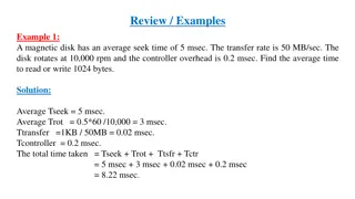
Speed/Access Time Seek Time: Time taken by head to move to a specific track. Latency/Rotation Delay: Time required to spin the desired sector under the head. Transfer Time: Time taken to transfer data. Access Time = Seek Time + Latency + Transfer Time
Storage capacity of Magnetic Tapes Storage capacity = Data recording density X Length.
RAID Redundant array of independent disks. Coined at university of Berkeley in 1987 as redundant array on inexpensive disks. Simultaneous data access by using multiple heads. Separate physical drives viewed by on a single drive.
Stripping: Data is segmented into equal-size partitions (the stripping unit), which are transparently distributed across multiple disks. Mirroring: Data is replicated across multiple redundant disks.
RAID Levels RAID Level 0 RAID Level 1 RAID Level 2 RAID Level 3 RAID Level 4 RAID Level 5 . .
RAID Controller Software Controller: Stored program concept. Hardware Controller: Hardware based.
RAID 0 Stripping No error correction No redundancy High sped transfer
RAID 1 Mirroring Mirroring makes exact copy of data Each write to both the dusks No error correction mechanism Provides fault tolerance
RAID 2 Parity used to introduce redundancy Error correction Fault tolerance Parallel access Small data stripes for high speed transfer
RAID 5 Independent access technique Block parity in distributed manner Fault tolerance
Optical Disks Used for backup memory. Circular disk, coated with a thin metal or some other material that is highly reflective. Read/Write operation can perform using laser beam. Has very high storing capacity, compares to magnetic floppy disks. Direct access device.
Storage Capacity of Optical Disks Storage capacity = Number of sectors X Number of bytes per sector.
Types of Optical Disks Compact Disks CD-ROM CD-R CD-RW Digital Versatile Disks DV-ROM DVD-R DVD-RW
Compact Disks First made in 1983. Data is encoded and read optically with a laser. Can store around 600MB to700 MB data.
CD-ROM Digital data is represented as a series of Pits and Lands: Pit: A little depression, forming a lower level in the track. Land: The flat part between pits, or the upper levels in the track.
CD drive transmits a low-power laser beam towards disk. Beam falls on a pit (rough surface) Low intensity reflected. Beam falls on a land (smooth surface) High intensity reflected. Photo-Sensor senses surface at regular intervals. Change in elevation Logic 1, otherwise Logic 0.
Organization of Data Reading a CD is done by shining a laser at the disk and detecting changing reflection patterns. 1: Change in height (land to pit or pit to land). 0: A fixed amount of time between 1 s. Note: We cannot have 1 s in a row.
CD-ROM Because of the heritage from CD audio, the data is stored as a single spiral track on the CD-ROM, contrary to magnetic had disk s discrete track concept. Thus, the rotation speed is controlled by CLV-Constant Linear velocity. The rotational speed at the center is highest, slowing down towards the outer edge. Because, the recording density is the same everywhere. Note that with CLV, the linear speed of the spiral passing under the R/W head remains constant. CLV is the result for the poor seek time in CD-ROMs. The advantage of CLV is that disk is utilized at its best capacity, as the recording density is the same everywhere.
CD-ROM Note that: Since 0 s are represented by the length of time between transitions, we must travel at constant linear velocity (CLV) on the tracks. Sectors are organized along a spiral. Sectors have same linear length. Advantage: Takes advantage of all storage space available. Disadvantage: Has to change rotational speed when seeking (slower towards the outside).
Digital Versatile Disc (DVD) The DVD (Digital Video Disc or Digital Versatile Disc) technology is based on CD technology with increased storage density. The DVD s come with a storage capacity of up to 17GB. Multi-layer Very high capacity (4.7GB to 17GB). Has same three types as CD.
Why DVD has higher data capacity?
