Understanding IEEE 802.11-20/0081r1 Transmission Terms
Dive into the terms related to synchronous and asynchronous transmission in IEEE 802.11-20/0081r1 standard, focusing on operations of Multi-Link Devices (MLDs) and Extremely High Throughput (EHT) STAs. Learn about terms such as SMLD, EBSL, SLBSS, and more that are crucial for maintaining efficient wireless communication. Explore the challenges and mechanisms associated with managing multiple links during transmission within a network environment.
Download Presentation

Please find below an Image/Link to download the presentation.
The content on the website is provided AS IS for your information and personal use only. It may not be sold, licensed, or shared on other websites without obtaining consent from the author. If you encounter any issues during the download, it is possible that the publisher has removed the file from their server.
You are allowed to download the files provided on this website for personal or commercial use, subject to the condition that they are used lawfully. All files are the property of their respective owners.
The content on the website is provided AS IS for your information and personal use only. It may not be sold, licensed, or shared on other websites without obtaining consent from the author.
E N D
Presentation Transcript
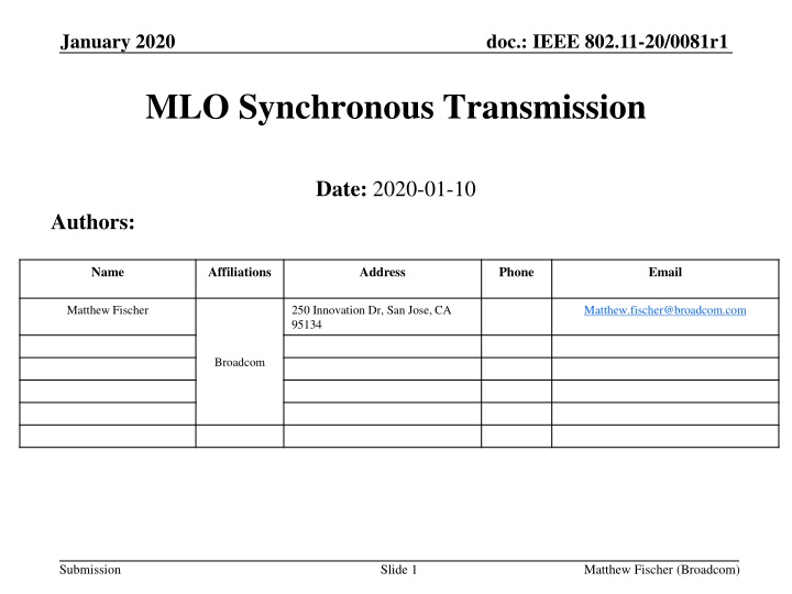
doc.: IEEE 802.11-20/0081r1 January 2020 MLO Synchronous Transmission Date: 2020-01-10 Authors: Name Affiliations Address Phone Email Matthew Fischer 250 Innovation Dr, San Jose, CA 95134 Matthew.fischer@broadcom.com Broadcom Submission Slide 1 Matthew Fischer (Broadcom)
doc.: IEEE 802.11-20/0081r1 January 2020 Abstract EHT non-AP STA devices will have operating conditions with restrictions on TX and RX behavior E.g. Simultaneous TX/RX might be restricted for certain link channel combinations for non-AP STA aka Synchronous mode When a Synchronous STA starts a TX on one Link1, medium state of Link2 is lost Due to NEXT Need mechanisms and rules to maintain Link2 medium state during Link1 TX operation Main mechanism is to synchronize PPDUs on both links Submission Slide 2 Matthew Fischer (Broadcom)
doc.: IEEE 802.11-20/0081r1 January 2020 Terms (1) MLD = Multi Link Device A device that can perform transmissions and receptions on more than one wireless interface link SMLD = Synchronous MLD Is an MLD that, during transmission on one link is unable to assess the medium condition on at least one other link according to the required performance limit of receiver minimum sensitivity EBSL = EDCA Backoff Suspended Link Is a link of an MLD for which EDCA has been suspended because a transmission by the same MLD on another link has caused an inability to assess the medium condition on this link within the required performance limit of receiver minimum sensitivity Submission Slide 3 Matthew Fischer (Broadcom)
doc.: IEEE 802.11-20/0081r1 January 2020 Terms (2) AMLD = Asynchronous MLD Is an MLD that, during transmission on one link is able to assess the medium condition on at least one other link according to the required performance limit of receiver minimum sensitivity Note: An MLD may have N links for which the relationship of any two links may be either Synchronous or Asynchronous EHT STA = Extremely High Throughput STA A STA that conforms to Extremely High Throughput definition of 802.11 TGbe EBSL EDCA Backoff Suspended Link Submission Slide 4 Matthew Fischer (Broadcom)
doc.: IEEE 802.11-20/0081r1 January 2020 Terms (3) SLBSS Synchronized Links BSS Submission Slide 5 Matthew Fischer (Broadcom)
doc.: IEEE 802.11-20/0081r1 January 2020 Synchronous Transmitter EDCA Problem RED is STA1 TX, other colors are STA1 RX Potential Loss of MPDUs at STA1 STA1 EDCA Resumes LINK1 RA=STAw, TA=STA1 BA R C LINK2 R R R STA1 EDCA DEAF RA=STAw, TA=STAx Potential Loss of MPDUs at STAx R C BA Potential Loss of MPDUs at STAw STA1 non-AP STA is the first TXOP winner STA1 begins TX on Link1 to STAw STAx attempts transmission to STAw during STA1 Link1 TX STA1 Link1 TX NEXT causes RX failure at STA1 Link2 At end of TX on Link1, STA1 identifies Link2 as IDLE Unless TX on Link2 > -62 at STA1 location Actually, no rule yet on STA1 Link2 CCA sensitivity during Link1 TX! STA1 Link2 Backoff quickly resumes and hits 0, STA1 TX on Link2 to STAw causes existing Link2 PPDU failures E.g. STAw == AP Submission Slide 6 Matthew Fischer (Broadcom)
doc.: IEEE 802.11-20/0081r1 January 2020 SyncTX EDCA Analysis (1) Link1 STA initiates TX, i.e. Link1 Backoff == 0 Link2 NO synchronous TX was possible E.g. simultaneous Link2 Backoff == 0 did NOT happen Link2 EDCA is deaf on Link2, due to Link1 TX Link2 indicates BUSY during Link1 TX due to NEXT Different implementations might not indicate BUSY! Link2 EDCA is in SUSPEND because of BUSY (new rule!) Link1 TX finishes, what happens on Link2? Link2 EDCA is out of synch with any other Link2 activity Can Link2 EDCA resume immediately? Is a wait period required? See DOZE AWAKE Submission Slide 7 Matthew Fischer (Broadcom)
doc.: IEEE 802.11-20/0081r1 January 2020 SyncTX EDCA Analysis (2) Link2 goes deaf during every Link1 TX Not good, not real EDCA, this is Partial EDCA! Worse than Quasi-asynchronous mode! I.e. completely deaf vs partially deaf! Except for NAV, PHY_LEN Techniques for PPDU alignment between Link1 and Link2 make EDCA deafness NOT MATTER Require Link2 to indicate BUSY during Link1 TX Then, when Link2 hearing is restored, a preamble is starting, or the medium has become free I.e. once PPDUs are aligned, deaf Link2 EDCA REMAINS IN SYNCH! Submission Slide 8 Matthew Fischer (Broadcom)
doc.: IEEE 802.11-20/0081r1 January 2020 Unrelated Transmission Alignment (1) RED is STA1 TX, other colors are STA1 RX STA1 EDCA Resumes LINK1 RA=STAw, TA=STA1 BA R C LINK2 RA=STAw, TA=STA1 R STA1 EDCA DEAF RA=STAw, TA=STAx R C BA C BA STA1 non-AP STA is the first TXOP winner STA1 begins TX on Link1 to STAw STAx attempts transmission to STAw during STA1 Link1 TX STAx aligns its PPDU to end at the same time as STA1 PPDU E.g. STAx has observed the PHY header of the STA1 TX PPDU STA1 Link1 TX NEXT causes RX blindness at STA1 Link2 At end of TX on Link1, STA1 sees start of PPDU on Link2 EDCA operates correctly E.g. STAw == AP Submission Slide 9 Matthew Fischer (Broadcom)
doc.: IEEE 802.11-20/0081r1 January 2020 Unrelated Transmission Alignment (2) 3000 2000 RA=STA1, TA=STAw BA BA RA=STA1, TA=STAw LINK1 R C C R RA=STA1, TA=STAx RA=STA1, TA=STAx LINK2 BA BA+Q Potential Loss of MPDUs STAx EDCA Link2 RTS DUR == 9500 Link2 CTS DUR == 3000, AKA Negotiated DUR CTS indicates amount of time available for PPDU+BA to create aligned operation STAx obeys CTS DUR in its following PPDU transmission, causing RX/TX alignment Alternatively, STAx can read PHY LEN from Link1 TX Uses PHY LEN to create alignment BA+Q contains AMPDU BA + QoS Data Enough symbols to align next transmissions, AKA Forced TXOP Sharing Slide 10 Submission Matthew Fischer (Broadcom)
doc.: IEEE 802.11-20/0081r1 January 2020 UTA RX RX with T 3000 2000 Same T Transmitter RA=STA1, TA=STAw BA+T RA=STA1, TA=STAw LINK1 R C BA+T C R RA=STA1, TA=STAx RA=STA1, TA=STAx LINK2 BA+T BA+T Potential Loss of MPDUs STAx EDCA BA+T contains AMPDU BA + Time/DUR information Time/DUR information indicates exact duration of next PPDU And other information similar to a Trigger E.g. TX power, Target RSSI, MCS, etc, as optionally desired And a suggested BA duration Same BA transmitter on both links, so they will be aligned All to be used if there is a next PPDU All intended to create alignment of subsequent PPDUs Submission Slide 11 Matthew Fischer (Broadcom)
doc.: IEEE 802.11-20/0081r1 January 2020 Rule Sets A Rules Alignment B Rules Backoff C Rules CTS, CTA Submission Slide 12 Matthew Fischer (Broadcom)
doc.: IEEE 802.11-20/0081r1 January 2020 A Rules (1) An MLD shall advertise whether it is operating as an SMLD or AMLD for a given pair of links The advertisement is dynamic, the relationship may change An AP MLD shall indicate whether any synchronous mode MLD are operating in the BSS The AP shall indicate the condition in Beacons and Probe Responses The existence of the condition invokes the use of A Rules, B Rules and C Rules The mode of operation is called SLBSS Synchronous Link BSS Submission Slide 13 Matthew Fischer (Broadcom)
doc.: IEEE 802.11-20/0081r1 January 2020 A Rules (2) An MLD that transmits a PPDU on a link to an MLD may request the MLD to transmit a Trigger on another link eliciting a response from the MLD on that other link An MLD that receives a request for a trigger may send such a Trigger An MLD that is receiving a PPDU from an SMLD on Link1 may send a trigger to the same SMLD on Link2 The trigger shall include an UL Length field value that elicits a response transmission whose last symbol end time matches the last symbol end time of the PPDU on Link1 The trigger may elicit an SU PPDU or an HE TB PPDU Submission Slide 14 Matthew Fischer (Broadcom)
doc.: IEEE 802.11-20/0081r1 January 2020 A Rules (3) A non-AP MLD may transmit up to one Trigger per link that is addressed to one user per link Including TRS type triggers An MLD that has received two PPDUs with the same end time from one or more MLDs on two links should ensure that the transmitted response PPDUs have the same end time An MLD that transmits a response to an MLD may include a Trigger in the response that elicits a PPDU from a different MLD or from the same MLD Submission Slide 15 Matthew Fischer (Broadcom)
doc.: IEEE 802.11-20/0081r1 January 2020 A Rules (4) An MLD that initiates transmission of a PPDU on a link should attempt to align the end of the last symbol of the transmission with the last symbol of any ongoing transmission on the other link If the associated AP MLD of the MLD has indicated that synchronous alignment is requested within the BSS An AP MLD shall indicate that synchronous alignment of transmissions is requested within the BSS if at least one associated MLD is operating in synchronous mode The indication is a dynamic indication and shall appear in the operation information of Beacons and Probe Responses Submission Slide 16 Matthew Fischer (Broadcom)
doc.: IEEE 802.11-20/0081r1 January 2020 A Rules (5) An MLD that initiates transmission of a PPDU on a link during an ongoing transmission on the other link should attempt to trigger the response to the PPDU to align with the response to the ongoing transmission By predicting the response length of the ongoing transmission By examining the trigger information from the ongoing transmission And using the trigger information to directly determine the length fo the response transmission on the other link Submission Slide 17 Matthew Fischer (Broadcom)
doc.: IEEE 802.11-20/0081r1 January 2020 A Rules (6) An MLD that initiates transmission of a response PPDU on a link should attempt to align the end of the last symbol of the transmission with the last symbol of any ongoing transmission on the other link If the associated AP MLD of the MLD has indicated that synchronous alignment is requested within the BSS Including its own transmission Submission Slide 18 Matthew Fischer (Broadcom)
doc.: IEEE 802.11-20/0081r1 January 2020 A Rules (7) Inserted Triggers should be: Repeated in multiple MPDUs within a PPDU To allow opportunity for 3rd parties to receive the information and use it for alignment of their transmissions As a separate Trigger MPDU, at the start of the PPDU To be identified early when decoding is possible Indicated in a new PHY Header field Response Length Submission Slide 19 Matthew Fischer (Broadcom)
doc.: IEEE 802.11-20/0081r1 January 2020 A Rules (8) Add a new PHY Header field Response length Add a new PHY Header field Transmitting MLD is a synchronous mode MLD Submission Slide 20 Matthew Fischer (Broadcom)
doc.: IEEE 802.11-20/0081r1 January 2020 A Rules (9) Everything is made simpler if one link is simply always operated as Trigger-only The STA that is transmitting the trigger can only transmit a trigger if: It knows the condition on the other link It creates a trigger that causes PPDU alignment on the triggered link with the ongoing PPDU on the non-triggered link Submission Slide 21 Matthew Fischer (Broadcom)
doc.: IEEE 802.11-20/0081r1 January 2020 A Rules (1) An MLD that has received two PPDUs with different end times from one or more MLDs on two links should attempt to ensure that the transmitted response PPDUs have the same end time Submission Slide 22 Matthew Fischer (Broadcom)
doc.: IEEE 802.11-20/0081r1 January 2020 B Rules (1) An SMLD shall suspend EDCA backoff countdown on a link when a transmission by the same SMLD on another link has caused an inability to assess the medium condition on this link within the required performance limit of receiver minimum sensitivity NAV counters and PHY Length based BUSY indication shall not be suspended The link is called an EBSL Submission Slide 23 Matthew Fischer (Broadcom)
doc.: IEEE 802.11-20/0081r1 January 2020 B Rules (2) An EBSL of an SMLD shall remain suspended until The NEXT disappears AND a minimum medium observation time equal to MMOT is performed Or A BUSY medium indication is detected using either frame detection or energy detection, or received Medium State Information, before MMOT time has elapsed Where medium observation time for a link is time during which there is no transmission on an interfering link, and during which there is an attempt to ascertain the state of the medium through detection of frame transmissions and energy detection Submission Slide 24 Matthew Fischer (Broadcom)
doc.: IEEE 802.11-20/0081r1 January 2020 B Rules (3) An SMLD monitors the medium on both Link1 and Link2 while not transmitting on either Link If the SMLD begins a transmission on Link1, then on Link2: The Intra NAV and Basic NAV counters continue to count down if not already at zero Any BUSY indication that is asserted as a result of a PHY Length field value is maintained per the PHY Length field value If the Link1 to Link2 NEXT allows ED operation on Link2 according to the ED threshold, ED operation continues on Link2 If the NEXT is above the ED threshold, Link2 shall be indicated as BUSY for the duration of the NEXT Optional transmission allowance If the Link2 Intra NAV and Basic NAV both are at or reach 0 and any PHY Length field value based BUSY indication has reverted to IDLE and NEXT is below the ED threshold and the ED indicates IDLE, then the SMLD may transmit on Link2 at DIFS following the transition from BUSY to IDLE of the last of the aforementioned items to have attained its zero or IDLE state, a PPDU from the AC with the lowest current backoff countdown value Submission Slide 25 Matthew Fischer (Broadcom)
doc.: IEEE 802.11-20/0081r1 January 2020 B Rules (4) A STA performing EDCA on a link for which MLO Synch Rules are enabled should Suspend the EDCA function if the start of a preamble is detected on another link of a set which is operating synchronously Should resume EDCA function after the PHY Header LENGTH information has been decoded, or has failed to be decoded At this resumption, no AIFS needs to be performed before resuming the countdown of IDLE slots If a STA does not suspend its EDCA function At the start of a preamble on another link of a set which is operating synchronously Then the STA shall use RTS-CTS or RTS-CTA or RTS-Trigger when it accesses the medium on that link and obey the timing constraints received in those frames Submission Slide 26 Matthew Fischer (Broadcom)
doc.: IEEE 802.11-20/0081r1 January 2020 B Rules (5) An MLD operating synchronously may Provide Medium State Information to another STA Submission Slide 27 Matthew Fischer (Broadcom)
doc.: IEEE 802.11-20/0081r1 January 2020 C Rules (1) An EHT STA that receives a CTS in response to an RTS where: The DUR field value of the CTS is not equal to RTS DUR field value minus 2xSIFS minus CTS Time Where CTS Time is the amount of time required to transmit the PPDU containing the CTS Shall ensure that the sum of 2xSIFS plus: The length in time of the Data PPDU that it transmits in response to the receipt of the CTS The length of the PPDU that is elicited in response to the Data PPDU Is equal to the value of the DUR field of the CTS Note that a value of 0 may be included in the CTS to indicate RTS recipient cannot accept the expected Data PPDU at this time RTS transmitter should not assume collision failure or BER failure RTS transmitter may retain current CW in backoff process instead of CW increment in response to CTS failure Submission Slide 28 Matthew Fischer (Broadcom)
doc.: IEEE 802.11-20/0081r1 January 2020 C Rules (2) Allow CTA response to RTS CTA includes DUR field as in CTS Specific information for the following frame including: PPDU duration MCS TX power Other parameters that would normally be found in a Trigger frame Duration of the BA or other elicited response frame CTA recipient transmits a PPDU according to the trigger-like information, including a trigger in the PPDU that triggers a response that corresponds to the response duration from the CTA Submission Slide 29 Matthew Fischer (Broadcom)
doc.: IEEE 802.11-20/0081r1 January 2020 C Rules (3) RTS recipient may respond with Trigger instead of CTS or CTA Choice of responding with Trigger can be made based on RTS RA value RA is set to the unique MLD address of the RTS recipient I.e. an RTS transmitter that addresses the RTS to the MLD address is capable of receiving a Trigger in response A RTS recipient may choose to attempt to transmit a Trigger in response to an RTS without knowledge of the ability of the RTS transmitter to receive such a sequence It might just work Submission Slide 30 Matthew Fischer (Broadcom)
doc.: IEEE 802.11-20/0081r1 January 2020 RTS Trigger Sequence Don t care, potential loss of MPDUs RA=STAw, TA=STA2 BA+T RA=STAz, TA=STAw+T LINK1 R C BA+T RA=STAw, TA=STA1 T R BA+T RA=STAx, TA=STA1+T LINK2 BA+T EDCA Trigger response to RTS Link1 recipient either: Wins contention on Link2 and transmits a Data PPDU that matches the duration of the Link1 transmission Not shown in the diagram Receives an RTS from some other STA and responds with a Trigger to force alignment of that STA transmission with the Link1 PPDU As depicted in the diagram Submission Slide 31 Matthew Fischer (Broadcom)
doc.: IEEE 802.11-20/0081r1 January 2020 Trigger vs TRS All discussions referring to Trigger frames can be extended to TRS Where TRS is a shortened form of a Trigger that is included in an A-control field Submission Slide 32 Matthew Fischer (Broadcom)
doc.: IEEE 802.11-20/0081r1 January 2020 Trigger Modifications (1) Any STA is allowed to transmit a Trigger I.e. not only an AP is allowed to transmit a Trigger Either in response to an RTS, or as an initial PPDU of a TXOP The Trigger should include parameters that cause The triggered PPDU to align with the other link PPDU The trigger is modified to include a field to indicate that the response to the Trigger is an SU PPDU Instead of an HE TB PPDU The Trigger may trigger more than one user to respond In which case, the response would be HE TB PPDU, not SU PPDU Submission Slide 33 Matthew Fischer (Broadcom)
doc.: IEEE 802.11-20/0081r1 January 2020 Trigger Modifications (2) The trigger is modified to allow the trigger to specify that the recipient is allowed to choose some of the parameters of the trigger response PPDU E.g. the trigger includes some means to signal that specific parameters are to be chosen by the trigger recipient, parameters, such as: MCS, RSSI Target, Spatial Reuse But the PPDU duration must be present and must be used by the trigger recipient In order to align the PPDU with the PPDU on other link(s) CS is not required Because RTS was used to solicit the Trigger, so medium IDLE condition and backoff access requirement is already satisfied Submission Slide 34 Matthew Fischer (Broadcom)
doc.: IEEE 802.11-20/0081r1 January 2020 Why Use RTS Trigger Sequence Need LSIG field from DATA PPDU to synchronize PPDU end times of different links But, what if: RTS transmitter only see the CTS, but not the DATA PPDU? RTS transmitter s two link MACs do not talk to each other Then RTS transmitter cannot synchronize it s Link2 PPDU end time with the PPDU end time of Link1 Trigger solves these problems But there s a period of ignorance to examine: Submission Slide 35 Matthew Fischer (Broadcom)
doc.: IEEE 802.11-20/0081r1 January 2020 RTS Considerations RTS DUR field value causes NAV to be set at 3rd party STAs Trigger might not allow transmission covering entire NAV 3rd party STAs might be stuck with NAV<>0 after triggered exchange is completed Those STAs are locked off of the channel RTS DUR field value should be a shorter value Since the Trigger response will dictate the final duration If the Link1 RTS-CTS exchange was observed, then the Link2 RTS should use the same NAV as the Link1 exchange, accounting for the passage of time RTS receiver does not know how much time the RTS transmitter needs, because the DUR is short Slide 36 Submission Matthew Fischer (Broadcom)
doc.: IEEE 802.11-20/0081r1 January 2020 Maybe Need to Delay The Trigger LSIG LENGTH not yet available LSIG LENGTH info available Don t care, potential loss of MPDUs RA=STAw, TA=STA2 BA+T RA=STAw, TA=STA2+T LINK1 R C BA+T N RA=STAw, TA=STA1 T R BA+T RA=STAw, TA=STA1+T LINK2 BA+T EDCA If Link2 backoff expires in the window from Link1 start of RTS to completion of Link1 Data PPDU LSIG field Link1 PPDU LSIG LENGTH not available in this window Responder to RTS can use techniques to delay the Trigger transmission until it has the LSIG LENGTH information to transmit E.g. send an NDP or two, or otherwise keep the Link2 medium BUSY Transmit the trigger once the LSIG LENGTH information is known Submission Slide 37 Matthew Fischer (Broadcom)
doc.: IEEE 802.11-20/0081r1 January 2020 Or Trigger A Short PPDU LSIG LENGTH not yet available LSIG LENGTH info available Don t care, potential loss of MPDUs RA=STAw, TA=STA2 BA+T RA=STAz, TA=STA2+T LINK1 R C BA+T T R RA=STAw, TA=STA1 BA+T RA=STAx, TA=STA1+T LINK2 RA=STAw TA=STA1 BA +T BA+T Second, alignment trigger, maybe combined with BA First short trigger EDCA Respond to RTS with a Trigger for a short duration I.e. a short trigger Really, a trigger that elicits a short response Follow up with a second trigger that matches the remainder of the Link1 PPDU I.e. a trigger that enforces an alignment with the other link Submission Slide 38 Matthew Fischer (Broadcom)
doc.: IEEE 802.11-20/0081r1 January 2020 UTA TX TX Case RTS Trigger (1) STA1 EDCA counts down to 0 DATA PPDUs RA=STAw, TA=STA1 BA LINK1 R T BUSY RA=STAw, TA=STA1 T BUSY LINK2 BA STAw EDCA counts down to 0 MLD AP has declared Link2 as Triggered only STA1 is the first TXOP winner, begins TX on Link1 with RTS STAw estimates time when backoff==0 on Link2 Potentially after the RTS reception STAw prepares Link1 Trigger response to RTS based on expected start time of Trigger on Link2, to align Trigger end times E.g. create Link1 Trigger that is longer than it needed to be STAw prepares Link1 and Link2 Triggers to have identical elicited response PPDU end times Link2 EDCA backoff==0 time is fairly predictable because of Trigger-only restricted operation on Link2 Data PPDUs potentially need TRS or Trigger to ensure that BA response PPDU durations are equal Slide 39 Submission Matthew Fischer (Broadcom)
doc.: IEEE 802.11-20/0081r1 January 2020 UTA TX TX Case RTS Trigger (2) STA1 EDCA counts down to 0 RA=STAw, TA=STA1 BA LINK1 R T BUSY RA=STAw, TA=STA1 T BUSY LINK2 BA STAw EDCA counts down to 0 STAw chooses to delay transmission MLD AP has declared Link2 as Triggered only STA1 is the first TXOP winner, begins TX on Link1 with RTS STAw sees start of RTS transmission STAw Link2 backoff expires during or even Before RTS reception Backoff on Link2 might have expired long before Link1 RTS reception begins! In any case, STAw optionally waits for outcome of RTS reception before transmitting on Link2 STAw detects opportunity for parallel Triggers to STA1 on Link1 and Link2 STAw transmits parallel Triggers to STA1 on Link1 and Link2 Submission Slide 40 Matthew Fischer (Broadcom)
doc.: IEEE 802.11-20/0081r1 January 2020 UTA TX TX Case RTS Trigger (3) In general in this scheme either: AP wins contention on Link1 and begins parallel, synchronized transmissions to one or more recipients Non-AP wins contention on Link1 and AP responds to RTS or RFT (see next slide) with Trigger on Link1 and optionally also on Link2 Triggers with common end times Trigger on Link1 is to RTS/RFT transmitter Trigger on Link2 is to either RTS/RFT transmitter or to another STA AP optionally transmits to data on Link2 to another STA that is synchronized to the Link1 transmission (e.g. TX RX case) I.e. synchronized in this case means common start and end times of the PPDUs I.e. generally, contention is only performed on Link1 while Link2 is triggered only for uplink (i.e. transmission of data to the AP) AP normal access for downlink on Link2, but normally synchronized with PPDUs on Link1 Submission Slide 41 Matthew Fischer (Broadcom)
doc.: IEEE 802.11-20/0081r1 January 2020 Additional TX TX Rules One link is EDCA operation Other link(s) triggered only (i.e. number of links may be greater than 2) Allow Any STA to TX Trigger i.e. not only AP Non-AP sends modified Triggers only I.e. no MU response, only SU response Generally maintain PPDU alignment between links E.g. common start and end times of PPDUs Create alternate to RTS E.g. RFT Request For Trigger Similar to RTS, but also: Include information in RFT regarding Whether RFT transmitter desires Trigger on other links, and if so, which links Desired length of trigger-elicited transmissions Submission Slide 42 Matthew Fischer (Broadcom)
doc.: IEEE 802.11-20/0081r1 January 2020 TX TX Last Word, Sort Of Response to Triggered Link2 PPDU might not match the length of the response to the Link1 PPDU Provide response length information in the trigger to ensure that the two responses match Not necessary if the responder is the same on both Links If responder is the same, then responder should align responses Submission Slide 43 Matthew Fischer (Broadcom)
doc.: IEEE 802.11-20/0081r1 January 2020 Switching TXOP Owners If AP estimates that Link1 transmitter will not receive a trigger, then AP would likely trigger a different STA If AP triggers a different STA, then AP aligns Link transmissions using Trigger parameters At end of aligned Link1 and Link2 transmissions, AP responds with BA on each Link AP can change the TXOP owner on Link2 AP can be encouraged to do this by a Trigger request Immediate trigger to requester is not possible, so switching TXOP owner is a delayed response to the trigger request See next slide Submission Slide 44 Matthew Fischer (Broadcom)
doc.: IEEE 802.11-20/0081r1 January 2020 UTA TX TX Case Triggered Swap RED is STA1 TX, other colors are STA1 RX BA RA==STA1, and T is for STA1 Trigger Request RA=STAw, TA=STA1 BA+T Q+T TA=STA1 LINK1 R C BA+Q BA Trig Q+T TA=STA1 RA=STAw, TA=STA2 LINK2 BA+T BA BA+Q BA RA==STA2, but T is for STA1 STAw EDCA STAw triggers STA2 on Link2 because Trigger reception will fail on Link2 for STA1 STA1 resumes monitoring Link2 at end of Link1 TX STAw BA response on Link2 includes a Trigger for STA1 I.e. delayed response to the request for trigger STA1 is now transmitting synchronously on Link1 and Link2 Submission Slide 45 Matthew Fischer (Broadcom)
doc.: IEEE 802.11-20/0081r1 January 2020 TX TX Priority Access (1) Allow Link1 Transmitter to transmit on Link2 when NAV and LENGTH collected and active on Link2 has expired: I.e. Link2 NAV, CRS LENGTH from before the start of the TX on Link1 Optionally use only Intra-BSS NAV, i.e. inter-BSS NAV is ignored When the last Link2 NAV, LENGTH expires, then: Any fully active EDCA STAs on Link2 will be resuming their backoff i.e. not initiating any TX STA1 may access Link2 after LIFS, no backoff resumption No other competition for Link2 because everyone else has a non-zero backoff and There is only one TX TX Priority access STA coming from Link1 (i.e. STA1) because there is only one winner on Link1 Submission Slide 46 Matthew Fischer (Broadcom)
doc.: IEEE 802.11-20/0081r1 January 2020 TX TX Priority Access (2) RED is STA1 TX, other colors are STA1 RX STA1 EDCA RA=STAw, TA=STA1 BUSY BA+T Q+T TA=STA1 LINK1 R C BA Q+T TA=STA1 RA=STAw, TA=STA1 LINK2 BA+T Data PPDU, TA=STAw B A R C BA STA1 NAV STA1 LIFS STA1 BSS Color observed, optional LIFS Note that Link2 RTS CTS is absent RTS CTS exchange is not possible because STA1 cannot RX a CTS on Link2 Optionally only allowed when the previous occupant on Link2 was intra- BSS E.g. STA1 BSS Color match observed in PPDU(s) within the preceding Link2 exchange Link IFS, a delay of [SIFS,SIFS+2xSLOT], without examining the medium Submission Slide 47 Matthew Fischer (Broadcom)
doc.: IEEE 802.11-20/0081r1 January 2020 TX TX Priority Access (3) Link2 preceding exchange might be a longer sequence E.g. the BA might be followed by another Data PPDU E.g. NAV value did not anticipate another transmission Add a bit to PHY Header to indicate if another PPDU will follow I.e. a bit that indicates that this PPDU is the next to last PPDU of a sequence I.e. set this bit to 1 in the PHY header of the Data PPDU with TA = STAw Optionally only allow the Priority access when the bit is found set to 1 Submission Slide 48 Matthew Fischer (Broadcom)
doc.: IEEE 802.11-20/0081r1 January 2020 SLBSS Rules When the AP indicates SLBSS Mode of operation All STA should initiate TXOPs with RTS Optional, if for example, the initiating STA has received PPDU length information from a link that is synchronous to the link on which it is initiating the TXOP In this case, the initiating STA can align its transmission end time to the ongoing PPDU end time without the need for assistance from a trigger Submission Slide 49 Matthew Fischer (Broadcom)
doc.: IEEE 802.11-20/0081r1 January 2020 Resolving Conflict STA1 tries to force alignment by STAx STAx might have its own TX/RX issues and might want to force ailgnment by STA1 Who has priority? First frame transmitted in time determines priority How is this resolved? No request translates to a requirement Each STA receiving instructions can decide on its own to obey or not Submission Slide 50 Matthew Fischer (Broadcom)

