Ultrasound Transducers: Applications and Functionality

Ultrasound transducers play a crucial role in medical imaging by converting electrical signals into ultrasonic energy for tissue penetration and image creation. This technology utilizes focused transducers to enhance resolution and penetration, while also managing beam intensity. The article delves into the concept of pressure intensity, side lobes, and the focal zone, providing insights into how these elements influence ultrasound imaging quality. Additionally, it explores the production and reception of ultrasound pulses through the composition and functions of transducer components.

Uploaded on Sep 13, 2024 | 2 Views
Download Presentation

Please find below an Image/Link to download the presentation.
The content on the website is provided AS IS for your information and personal use only. It may not be sold, licensed, or shared on other websites without obtaining consent from the author.If you encounter any issues during the download, it is possible that the publisher has removed the file from their server.
You are allowed to download the files provided on this website for personal or commercial use, subject to the condition that they are used lawfully. All files are the property of their respective owners.
The content on the website is provided AS IS for your information and personal use only. It may not be sold, licensed, or shared on other websites without obtaining consent from the author.
E N D
Presentation Transcript
Pressure Intensity The pressure intensity at a point can be calculated using the solution of wave equation: 1D case Circular aperture The pressure distribution is proportional with the fourier transform of the aperture.
Side Lobes Side lobes are small beams of greatly reduced intensity that are emitted at angles to the primary beam and they often cause image artifacts. the origin of these lobes are due from radial vibrations from the edges of the transducer
Focused Transducers High frequency beams have two advantages over low-frequency beams: (1) axial resolution is superior; and (2) the Fresnel zone is longer It would seem logical to use high frequencies for all imaging. High frequencies however, have a major drawback related to penetration. Tissue absorption increases with increasing frequency, so a relatively low frequency beam is required to penetrate thick parts. It would then seem logical to use low frequency transducers and to increase the size of the transducer to keep the beam coherent for sufficient depth to reach the point of interest (longer Fresnel zone). Although larger transducers improve coherence they deteriorate lateral resolution. The dilemma is at least partially resolved with the use focused transducers. NOTE focused transducers reduce beam width which improves lateral resolution they also concentrate beam intensity thereby increasing penetration and echo intensity thus improving image quality
the focal zone is the region over which the beam is focused the focal length is the distance from the transducer to the centre of the focal zone the depth of focus is the distance over which the beam is in a reasonable focus a small diameter transducer has a shorter focal zone and spreads more rapidly in the far zone most diagnostic transducers are focused, which is achieved using a either a curved piezoelectric crystal, an acoustic lens or electronics (phased arrays)
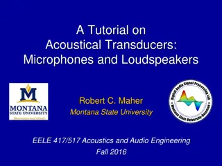
Ultrasound Pulse Production and Reception A transducer is a device that can convert one form of energy into another. Ultrasound transducers are used to convert an electrical signal into ultrasonic energy that can be transmitted into tissue, and to convert ultrasonic energy reflected back from the tissue into an electrical signal. The general composition of an ultrasound transducer is shown below: the most important component is a thin piezoelectric (crystal) element located near the face of the transducer the front and back face of the element is coated with a thin conducting film to ensure good contact with the two electrodes the outside electrode is grounded to protect the patient from electrical shock an insulated cover is used to make the device watertight an acoustic insulator made of cork or rubber is used to prevent the passing of sound into the housing (i.e.: reduces transducer vibrations) the inside electrode is against a thick backing block that absorbs sound waves transmitted back into the transducer
Transducers, (apertures) Bulk Acoustic wave transducers Surface acoustic wave transducers quartz crystal microbalance
In the bulk of an ideally infinite unbounded solid, two types of bulk acoustic waves (BAW) can propagate. They are the longitudinal waves, also called compressional/extensional waves, and the transverse waves, also called shear waves, which respectively identify vibrations where particle motion is parallel and perpendicular to the direction of wave propagation. When a single plane boundary interface is present forming a semi- infinite solid, surface acoustic waves (SAW) can propagate along the boundary.
Probably the most common type of SAWs are the Rayleigh waves, which are actually two-dimensional waves given by the combina- tion of longitudinal and transverse waves and are confined at the surface down to a penetration depth of the order of the wavelength. Shear horizontal (SH) particle displacement has only a very low pene- tration depth into a liquid, hence a device with pure or pre- dominant SH modes can operate in liquids without significant radiation losses in the device. Love waves (LW), where the acoustic wave is guided in a foreign layer Plate waves, also called Lamb waves, require two parallel boundary planes. flexural plate wave (FPW)
Bulk Wave: Conventional piezo CMUT Thin film SAW Microfabrication CMUT
Why should the transducer thickness be equal to 1/2 of the desired wavelength? Back surface A Front surface C B D Backing Block Patient Thickness (t) When the piezoelectric element is driven by a alternating voltage the crystal vibrates (i.e.: the width of the crystal moves back and forth). The front face of the crystal emits sound both in the forward and backward directions as does the back surface. wave front (A) will get absorbed by the transducer s backing material wave front (D) will enter into the patient the wave front (C) is reflected at the back face of the disk, and by the time it joins wave front (D), it has traveled an extra distance 2t. If this distance equals a wavelength the wave fronts (D) and (C) reinforce for they are in phase, and constructive interference or resonance occurs. if wave fronts (D) and (C) are not in phase, then there will be some destructive interference same reasoning applies to wave front (B)
Creating a sound wave from an electrical pulse When a positive voltage (A) is applied across the surface of the crystal, it creates an electric field across the crystal surface which cause the molecules (dipoles) in the crystal to realign and thus changing the shape (width) of the crystal. A C B Voltage Pulse Positive Time Negative When the voltage polarity is changed from positive to negative, there is a point in time when the electric field across the crystal is zero (at voltage equal to zero) and the crystal relaxes (B). When the voltage polarity is reversed (i.e.: negative) the crystal realigns once again and changes its width once again (C).
The net effect the alternating voltage pulse has on the crystal is to make it oscillate back and forth about its width. This change in shape of the crystal increases and decreases the pressure in front of the transducer, thus producing ultrasound waves. Ultrasound wave direction Rarefaction region created when crystal surface is contracting (less pressure on surface) wavefront diagram Compression region created when crystal surface is expanding (more pressure on surface) Ultrasound wave direction
CMUT vs Piezoelectric The frequency of operation depends on the cell size (cavity of membrane), and on the stiffness of the material used as a membrane. As it is built on silicon, the integration of electronics would be easier for the CMUTs compared to other transducer technologies. Large Bandwith/High frequency Smaller dimensions
Resonant Frequency The frequency at which the transducer is the most efficient as a transmitter of sound is also the frequency at which it is most sensitive as a receiver of sound. This frequency is called the natural or resonant frequency of the transducer. the thickness and the material (i.e.: speed of sound in the crystal) of the piezoelectric crystal determines the resonant frequency of the transducer transducers crystals are normally manufactured so that their thickness (t) is equal to one-half of the wavelength ( ) of the ultrasound produced by the transducer Bandwidth Resonant Frequency The range of frequencies in the emitted ultrasound wave is called the bandwidth and is defined to be the full width of the frequency distribution at half maximum (FWHM). bandwidth SPL Spatial Pulse Length (SPL)
Continuous voltage waveform Pulsed voltage waveform Frequency distribution of emitted ultrasound wave Continuous waveform can be represented by a single sine wave (one frequency), thus frequency distribution is very narrow Pulsed waveform can be represented by the sum of many sine waves each of different frequency, thus frequency distribution is wide
Q-factor The Q-factor of a transducer system describes the shape of the frequency distribution (response curve) and is defined as Q-factor = f0 (f2 - f1) Bandwidth = (f2 - f1) where f0 is the resonance frequency, f1 is the frequency below resonance at which intensity is reduced by half and f2 is the frequency above resonance at which intensity is reduced by half high Q transducers produce relatively pure frequency spectrums and low Q transducers produce a wider range of frequencies short pulses correspond to reduce Q values and vice versa bandwidth Q-factor
Pulse Ultrasound Mode Because a transducer can be a transmitter and a receiver of ultrasonic energy, it clearly stands to reason that a continuous voltage waveform can not be used. If such a waveform was used, the transducer would always function as a transmitter. Since the internally generated sound waves are stronger than the returning echoes, the returning signal is lost in the noise of the system. To over come this problem, most transducers are used in a pulse mode where the voltage waveform consists of many pulses each separated by a fixed distance and time. The transducer functions as a transmitter during pulse excitation and as a receiver during the time interval between pulses. Voltage waveform Ultrasound pulses produced by transducer NOTE most transducers are designed to have short pulses (improved resolution) with low Q values (broad bandwidth - desirable in order to receive echoes of many different frequencies)
Pulse Repetition Frequency (PRF) PRF is the number of pulses occurring in 1 second Pulse Repetition Period (PRP) PRP is the time from the beginning of one pulse to the beginning of the next pulse
Spatial Pulse Length (SPL) SPL is the length of space over which a single pulse occurs, and is defined as SPL = n where n is the number of cycles in the pulse and is the wavelength. NOTE An important parameter when considering axial resolution


")


")
")