SHEET METAL PROCESSES
Bending is a common sheet metal forming operation used to shape seams, corrugations, and flanges while providing stiffness to the part. Learn about bend allowances, minimum bend radius, and bending forces in sheet metal processes.

Uploaded on Feb 20, 2025 | 1 Views
Download Presentation

Please find below an Image/Link to download the presentation.
The content on the website is provided AS IS for your information and personal use only. It may not be sold, licensed, or shared on other websites without obtaining consent from the author.If you encounter any issues during the download, it is possible that the publisher has removed the file from their server.
You are allowed to download the files provided on this website for personal or commercial use, subject to the condition that they are used lawfully. All files are the property of their respective owners.
The content on the website is provided AS IS for your information and personal use only. It may not be sold, licensed, or shared on other websites without obtaining consent from the author.
E N D
Presentation Transcript
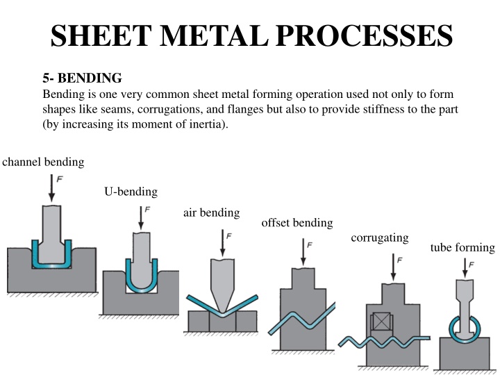
SHEET METAL PROCESSES 5- BENDING Bending is one very common sheet metal forming operation used not only to form shapes like seams, corrugations, and flanges but also to provide stiffness to the part (by increasing its moment of inertia). channel bending U-bending air bending offset bending corrugating tube forming
As a sheet metal is bent (Fig 6.2), its fibers experience a distortion such that those nearer its outside, convex surface are forced to stretch and come in tension, while the inner fibers come in compression. Somewhere, in the cross section, there is a plane which separates the tension and compression zones. This plane is parallel to the surface around which the sheet is bending, and is called neutral axis. The position of neutral axis depends on the radius and angle of bend. Further, because of the Poisson's ratio, the width of the part L in the outer region is smaller, and in the inner region it is larger, than the initial original width. Sheet metal bending. It may be noted that the bend radius is measured to the inner surface of the bent part.
5-1 BEND ALLOWANCE It is the length of the neutral axis in the bend, Fig 6.2. This determines the blank length needed for a bent part. It can be approximately estimated from the relation Lb = ( R + k t ) where, Lb = bend allowance (mm) t = thickness of sheet (mm), and whose value may be taken as 1/3 when R < 2t, and as 1/2 when R 2t. = bend angle (radian) R = bend radius (mm) k = constant,
Example A 20 mm wide and 4 mm thick C 20 steel sheet is required to be bent at 600 at bend radius 10 mm. determine the bend allowance. Solution. Here, bend radius R = 10 mm Sheet thickness t= 4 mm Since R > 2t, k = 0.5 = =2 * 360 radian 60 Bend Allowance Lb = (R + k t) = (2 * 60 360) (10 + 0.5*4) = 12.56 mm
5-2 MINIMUM BEND RADIUS As the ratio of the bend radius to the thickness of sheet (R / t) decreases, the tensile strain on the outer fibers of sheet increases. If R / t decrease beyond a certain limit, cracks start appearing on the surface of material. This limit is called Minimum Bend Radiusfor the material. Minimum bend radius is generally expressed in terms of the thickness of material, such as 2t, 3t, 4t, etc. Table 6.1 gives the minimum bend radius allowed for different materials Condition Material Soft Hard Aluminum alloys 0 6t Beryllium copper 0 4t Brass, low-leaded 0 2t Magnesium Steels 5t 13t Austenitic stainless 0.5t 6t Low-carbon, low-alloy 0.5t 4t Titanium 0.7t 3t Titanium alloys 2.6t 4t
5-3 Bending Force : There are two general types of die bending: V die bending and wiping die bending. V Die bending is used expensively in brake die operations and stamping die operations. The bending force can be estimated from the following simple relation. 0 P = k.Y.L.t2 / w Where P is bending force, Y is the yield stress of the material, L is the bend length (bend allowance) t is the sheet thickness, w is the die opening and k is a constant whose value can be taken as 1.3 for a V-die and 0.3 for a wiping die. (Fig 6.3) shows various types of bending dies. wipingdie V-die Bending force varies as the punch progresses through the bending operation. The force is zero in the beginning. It rises and reaches the maximum value as the punch progresses and reaches the bottom of the stroke.
Example: A 400 mm long and 2.5 mm thick piece of carbon steel sheet is required to be bent at 900 using a V die. You may assume the yield stress of the material as 500 MPa and the die opening as 10 times the material thickness. Estimate the force required for the operation. Solution : Here, Y = 500 MPa L = 400 mm t = 2.5 mm k = 1.3 (for V die) w = 25 mm Bending force P = k.Y.L.t2 / w = 1.3 x 500 x 400 x (2.5)2 / 25 = 65 KN Example : If the material as mentioned in the above example is to be bent at 900 using wiping die with radius = 3.75 mm, what is the force requirement? Solution : Here, Y = 500 MPa L = 400 mm t = 2.5 mm k = 0.3 w = 2.5 + 3.75 + 3.75 = 10 mm (see Fig 6.4) Bending force P = k.Y.L.t2 / w = 0.3 x 500 x 400 x (2.5)2 / 10 = 37.5 KN

, its fibers experience a")