Shaft Stress Analysis and Design Equations
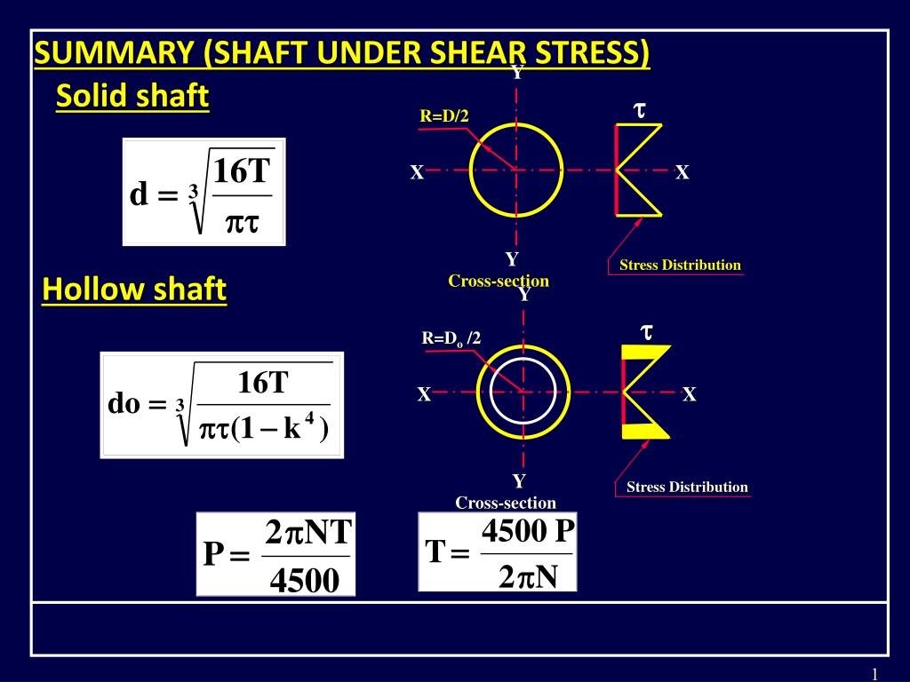
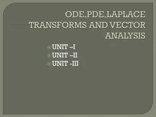
SUMMARY (SHAFT UNDER SHEAR STRESS)
SUMMARY (SHAFT UNDER SHEAR STRESS)
S
S
o
o
l
l
i
i
d
d
s
s
h
h
a
a
f
f
t
t
1
5.2 SHAFTS UNDER BENDING MOMENT
5.2 SHAFTS UNDER BENDING MOMENT
The shafts; which rotate under the action of pure
The shafts; which rotate under the action of pure
bending moment; are subjected to a uni-axial state of
bending moment; are subjected to a uni-axial state of
tensile and compressive stress.
tensile and compressive stress.
This also the case of the
This also the case of the
axles
axles
, which transmit bending
, which transmit bending
moment only The design of both of them should be
moment only The design of both of them should be
based on the following bending equation:
based on the following bending equation:
D
e
s
i
g
n
-
G
e
a
r
b
o
x
-
A
n
i
m
a
t
i
o
n
2
M
M
t1
t1
M
M
t2
t2
M
M
t1
t1
< M
< M
t2
t2
N
1
> N
2
3
where;
M :Maximum bending moment acting on the critical
M :Maximum bending moment acting on the critical
section in N.mm
section in N.mm
I : Second moment of inertia of the cross section
I : Second moment of inertia of the cross section
about the axis of rotation in mm
about the axis of rotation in mm
4
4
.
.
b
b
: Normal stress due to bending moment in kp/cm
: Normal stress due to bending moment in kp/cm
y : The distance from the neutral axis to the outer
y : The distance from the neutral axis to the outer
most fiber on which the stress is maximal in mm
most fiber on which the stress is maximal in mm
.
.
4
F
F
o
o
r
r
s
s
o
o
l
l
i
i
d
d
c
c
i
i
r
r
c
c
u
u
l
l
a
a
r
r
s
s
h
h
a
a
f
f
t
t
:
:
&
Therefore, the diameter of solid shafts can be
Therefore, the diameter of solid shafts can be
determined from the following equation:
determined from the following equation:
5
F
F
o
o
r
r
h
h
o
o
l
l
l
l
o
o
w
w
c
c
i
i
r
r
c
c
u
u
l
l
a
a
r
r
s
s
h
h
a
a
f
f
t
t
:
:
&
&
Therefore, the diameter of solid shafts can be determined
Therefore, the diameter of solid shafts can be determined
from the following equation:
from the following equation:
6
5.3 SHAFTS SUBJECTED TO COMBINED STATE OF
5.3 SHAFTS SUBJECTED TO COMBINED STATE OF
STRESS
STRESS
In most practical cases, the shafts are subjected in
In most practical cases, the shafts are subjected in
general into a combination of bending and twisting
general into a combination of bending and twisting
moments as well as normal force.
moments as well as normal force.
The design of these shafts should be based on the
The design of these shafts should be based on the
simultaneously effect of all the loading elements.
simultaneously effect of all the loading elements.
The theories of elastic failure must be carefully utilized.
The theories of elastic failure must be carefully utilized.
According to practical experience, the following two theories
According to practical experience, the following two theories
are important in the design of these shafts:
are important in the design of these shafts:
1-
1-
Maximum shear stress theory of elastic failure
Maximum shear stress theory of elastic failure
(Guest`s theory)
(Guest`s theory)
2- Maximum normal stress theory
2- Maximum normal stress theory
(Rankine`s theory).
(Rankine`s theory).
7
Maximum Shear Theory
Maximum Shear Theory
According to the maximum shear stress theory of
According to the maximum shear stress theory of
elastic failure, the maximum shear stress in the shaft
elastic failure, the maximum shear stress in the shaft
can be expressed as follows:
can be expressed as follows:
Where,
Where,
s
s
: Shear stress due to twisting moment.
: Shear stress due to twisting moment.
b
b
: Normal stress due to bending moment.
: Normal stress due to bending moment.
8
Replacing the normal and shear stresses with their
Replacing the normal and shear stresses with their
equations, which are functions of the shaft diameter
equations, which are functions of the shaft diameter
and the loads (i.e. bending and twisting moments), the
and the loads (i.e. bending and twisting moments), the
following relation can be obtained:
following relation can be obtained:
9
Therefore, the following equation can be used to
evaluate the diameter of the shaft according to the
maximum shear stress theory of elastic failure.
10
In The case of hollow shafts, the external diameter can
be determined according to the following equation:
11
Maximum normal stress theory
According to the maximum normal stress theory of
elastic failure, the maximum normal stress in the shaft
can be expressed as follows:
Where,
s
: Shear stress due to twisting moment, N/mm
2
.
b
: Normal stress due to bending moment, N/mm
2
.
Where,
yt
: Yield stress of shaft material, N/mm
2
1
: Maximum principale stress, N/mm
2
12
Using the same treatment that has been used in the
maximum shear stress theory, the following equation can
be obtained:
13
14
The following table summarize the equations used in design
The following table summarize the equations used in design
of shaft using the allowable stress as material property.
of shaft using the allowable stress as material property.
15
SOLVED PROPLEM (1)
SOLVED PROPLEM (1)
A line shaft rotates at 200 r.p.m. and transmits 25
A line shaft rotates at 200 r.p.m. and transmits 25
HP. The shaft made of mild steel with an allowable
HP. The shaft made of mild steel with an allowable
shear stress of 420 kp/cm
shear stress of 420 kp/cm
2
2
. Determine the diameter
. Determine the diameter
of the shaft neglecting the bending moment on it.
of the shaft neglecting the bending moment on it.
16
I.
Determination of thetransmitted torque:
Determination of thetransmitted torque:
Let T = Torque transmitted by the shaft
Let T = Torque transmitted by the shaft
17
I.
II. Diameter of the shaft
II. Diameter of the shaft
Let d = shaft diameter
Let d = shaft diameter
18
SOLVED PROPLEM (2)
SOLVED PROPLEM (2)
Find the diameter of a solid steel shaft transmits
Find the diameter of a solid steel shaft transmits
25 HP at 200 r.p.m. The ultimate shear stress is
25 HP at 200 r.p.m. The ultimate shear stress is
3600 kp/cm
3600 kp/cm
2
2
and a factor of safety as 8 .
and a factor of safety as 8 .
If a hollow shaft is assumed to replace it, find the
If a hollow shaft is assumed to replace it, find the
inside and outside diameters when a ratio of
inside and outside diameters when a ratio of
inside diameter to outside diameter of 0.5 is
inside diameter to outside diameter of 0.5 is
assumed.
assumed.
SOLUTION
SOLUTION
Given
Given
Horse power transmitted,
Horse power transmitted,
P =25 h.p.
P =25 h.p.
Speed of shaft,
Speed of shaft,
N =200 r.p.m.
N =200 r.p.m.
Ultimate shear stress,
Ultimate shear stress,
u
u
=3600 kp/cm2
=3600 kp/cm2
Factor of safety
Factor of safety
n = 8
n = 8
Allowable shear stress,
Allowable shear stress,
all
all
= 3600/8 =450 kp/cm2
= 3600/8 =450 kp/cm2
19
I.
Determination of thetransmitted torque:
Determination of thetransmitted torque:
Let T = Torque transmitted by the shaft
Let T = Torque transmitted by the shaft
20
II. Diameter of the shaft
II. Diameter of the shaft
Let d = shaft diameter
Let d = shaft diameter
21
This content discusses the analysis and design considerations for shafts under shear stress, bending moment, and combined states of stress. It covers stress distribution, equations for solid and hollow shafts, and important theories for shaft design. The material provides insights into determining shaft dimensions based on maximum shear stress and bending moments.

Download Presentation

Please find below an Image/Link to download the presentation.
The content on the website is provided AS IS for your information and personal use only. It may not be sold, licensed, or shared on other websites without obtaining consent from the author.If you encounter any issues during the download, it is possible that the publisher has removed the file from their server.
You are allowed to download the files provided on this website for personal or commercial use, subject to the condition that they are used lawfully. All files are the property of their respective owners.
The content on the website is provided AS IS for your information and personal use only. It may not be sold, licensed, or shared on other websites without obtaining consent from the author.
E N D
Presentation Transcript
SUMMARY (SHAFT UNDER SHEAR STRESS) Solid shaft Y R=D/2 16 T X X = = d 3 Y Stress Distribution Cross-section Hollow shaft Y R=Do/2 16 T = = X X do 3 4) 1 ( k Y Stress Distribution Cross-section = =4500 2 = =2 NT P T P N 4500 1
5.2 SHAFTS UNDER BENDING MOMENT The shafts; which rotate under the action of pure bending moment; are subjected to a uni-axial state of tensile and compressive stress. This also the case of the axles, which transmit bending moment only The design of both of them should be based on the following bending equation: Gear 1 A B Gear 3 C Gear 2 Design- Gearbox-Animation 2
Mt1 Gear 1 A B Gear 3 Mt2 C Gear 2 Mt1< Mt2 N1> N2 3
Y R=D/2 A My I b = = X X where; M :Maximum bending moment acting on the critical section in N.mm I : Second moment of inertia of the cross section about the axis of rotation in mm4. b: Normal stress due to bending moment in kp/cm y : The distance from the neutral axis to the outer most fiber on which the stress is maximal in mm. Y Stress Distribution Cross-section 4
For solid circular shaft: = = d 4 I d = =2 y & 64 M d ( b ) 2 = = b 4 d 64 Therefore, the diameter of solid shafts can be determined from the following equation: 32 M = = b d 3 b 5
For hollow circular shaft: = = d = = o y & 4 o 4 I d ( d ) 2 64 i M ( d 2 ) M d ( b ) 2 = = = = b o b b 4 o d or, 4 o 4 i d ( d ) 4 ( 1 k ) 64 64 Therefore, the diameter of solid shafts can be determined from the following equation: 32 M d = = b d = = 3 k i e . i ., k 1 4 1 ( k ) d b o 6
5.3 SHAFTS SUBJECTED TO COMBINED STATE OF STRESS In most practical cases, the shafts are subjected in general into a combination of bending and twisting moments as well as normal force. The design of these shafts should be based on the simultaneously effect of all the loading elements. The theories of elastic failure must be carefully utilized. According to practical experience, the following two theories are important in the design of these shafts: 1- Maximum shear stress theory of elastic failure (Guest`s theory) 2- Maximum normal stress theory (Rankine`s theory). 7
Maximum Shear Theory According to the maximum shear stress theory of elastic failure, the maximum shear stress in the shaft can be expressed as follows: 1 2 b 2 s = = + + 4 (max) s 2 Where, s b : Shear stress due to twisting moment. : Normal stress due to bending moment. 8
Replacing the normal and shear stresses with their equations, which are functions of the shaft diameter and the loads (i.e. bending and twisting moments), the following relation can be obtained: 2 2 1 32 M 16 T = = + + 4 (max) 3 3 2 d d 16 2 2 = = + + M ( ) ( T ) 3 d 2 2 = = + + T M T e Teis known as the equivalent twisting moment. 9
Therefore, the following equation can be used to evaluate the diameter of the shaft according to the maximum shear stress theory of elastic failure. 2 2 + + 16 M T = = d 3 max 16 T = = d e 3 max 10
In The case of hollow shafts, the external diameter can be determined according to the following equation: 16 T = = e d 3 o 4 1 ( k ) max 11
Maximum normal stress theory According to the maximum normal stress theory of elastic failure, the maximum normal stress in the shaft can be expressed as follows: = = Where, yt : Yield stress of shaft material, N/mm2 1 : Maximum principale stress, N/mm2 yt 1 1 1 2 = = + + + + 2 ( ) (max) yt b b s 2 2 Where, s b : Shear stress due to twisting moment, N/mm2. : Normal stress due to bending moment, N/mm2. 12
Using the same treatment that has been used in the maximum shear stress theory, the following equation can be obtained: 3 2 2 = = + + + + d M ( M T ) yt 32 M 2 1 is defined as the equivalent The term 2 2 + + + + M T bending moment, i.e.: 1 2 2 = = + + + + M M M T e 2 13
32 M = = e d 3 yt In The case of hollow shafts, the external diameter can be determined according to the following equation: 32 M = = e d 3 o 1 ( 4 k ) yt 14
The following table summarize the equations used in design of shaft using the allowable stress as material property. Method Solid Shaft Hollow Shaft Pure Shear Stress (Mt) 16 T 16 T = = do = = d 3 3 4) ( 1 k max Pure Normal Stress (Mb) 32 M 32 M = = b d = = b d 3 3 o 1 ( 4 k ) b b Max. Shear Theory (Mb&Mt) 2 2 + + 16 M T 2 2 + + 16 M T = = d = = d 3 3 o 4 ( 1 k ) max max Principle Normal Stress Theory (Mb&Mt) 32 M 32 M = = e d = = e d 3 3 o 1 ( 4 k ) yt yt 15
SOLVED PROPLEM (1) A line shaft rotates at 200 r.p.m. and transmits 25 HP. The shaft made of mild steel with an allowable shear stress of 420 kp/cm2. Determine the diameter of the shaft neglecting the bending moment on it. SOLUTION Given N = 200 r.p.m. P = 25 h.p. ( all) = 420 kp/cm2 16
I. Determination of thetransmitted torque: Let T = Torque transmitted by the shaft 4500 P = = T 2 N 25 x 4500 = = = = T 89 5 . kp m . 2 x 200 = = T 8950 kp cm . i.e. T=8950 kp.cm 17
I. Let d = shaft diameter II. Diameter of the shaft 16 T = = d 3 all 16 x 8950 = = = = d 4 77 . cm 3 x 420 i.e. d =47.7 mm Therefore, d = 50 mm 18
SOLVED PROPLEM (2) Find the diameter of a solid steel shaft transmits 25 HP at 200 r.p.m. The ultimate shear stress is 3600 kp/cm2and a factor of safety as 8 . If a hollow shaft is assumed to replace it, find the inside and outside diameters when inside diameter to outside diameter of 0.5 is assumed. SOLUTION Given Horse power transmitted, P =25 h.p. Speed of shaft, N =200 r.p.m. Ultimate shear stress, u=3600 kp/cm2 Factor of safety n = 8 Allowable shear stress, all= 3600/8 =450 kp/cm2 a ratio of 19
I. Determination of thetransmitted torque: Let T = Torque transmitted by the shaft 4500 P = = T 2 N 25 x 4500 = = = = T 89 5 . 2 x 200 = = T 8950 kp cm . i.e. T=8950 kp.cm 20
II. Diameter of the shaft Let d = shaft diameter 16 T = = d 3 all 16 x 8950 = = = = d 4 77 . cm 3 x 420 i.e. d =47.7 mm Therefore, d = 50 mm 21
")


")


")