Radio Wave Propagation for Amateur Radio Technicians

Amateur Radio Technician
Exam Prep Course
Module 4
Propagation, Antennas, and Feed Lines
4.1
 
Propagation
4.2
 
Antenna and Radio Wave Basics
4.3
 
Feed Lines and SWR
4.4
 
Practical Antenna Systems
Propagation
 
Radio waves propagate in many ways depending on …
Frequency of the wave
Characteristics of the environment
 
We will discuss three basic ways:
Line of sight
Ground wave
Sky wave
Line of Sight
 
Radio energy can travel in a straight line from a transmitting antenna
to a receiving antenna – called the 
direct path
There is some attenuation of the signal as the radio wave travels due
to spreading out
This is the primary propagation mode for VHF and UHF signals
Radio waves can be reflected by any sudden change in the path they
are traveling, such as a building, hill, or even weather-related changes
in the atmosphere
Vegetation can also absorb VHF and UHF radio waves
Precipitation such as fog and rain can absorb microwave and UHF
radio waves although it has little effect at HF and on the lower VHF
Bands
Ground Wave
 
At lower HF frequencies radio waves can follow the Earth’s surface
These waves will travel beyond the range of line-of-sight
Range of a few hundred miles
Reflect, Refract, Diffract
 
Radio waves are reflected by any conductive surface
Ground, water, buildings
Refraction
 or bending occurs when waves encounter a medium having a
different speed of light, such as water or an electrical feed line
By bending signals slightly back towards the ground, refraction
counteracts the curvature of the Earth and allows signals to be received at
distances beyond the visual horizon
Knife edge diffraction
: Diffraction as waves travel past sharp edges of large
objects
Multipath
 
Radio signals arriving at a receiver after taking different paths from
the transmitter
Results in irregular fading, even when reception is generally good
Because “dead spots” from multipath are usually spaced about ½-
wavelength apart, VHF or UHF signals from a station in motion can
take on a rapid variation in strength known as 
mobile flutter 
or 
picket-
fencing
Distortion caused by multipath can also cause VHF and UHF digital
data signals to be received with a higher error rate, even though the
signal may be strong
Tropospheric Propagation
 
Propagation at and above VHF frequencies are assisted by variations
in the atmosphere
Variations such as weather fronts or temperature inversions create
layers of air next to each other that have different characteristics
The layers form structures called ducts that can guide even
microwave signals for long distances
Regularly used by amateurs to make VHF and UHF contacts that
would otherwise be impossible by line-of-sight propagation (300
miles or more)
PRACTICE QUESTIONS
Why do VHF signal strengths sometimes vary greatly when
the antenna is moved only a few feet?
A.
The signal path encounters different concentrations of water vapor
B.
VHF ionospheric propagation is very sensitive to path length
C.
Multipath propagation cancels or reinforces signals
D.
All these choices are correct
 
T3A01 C 4-1
What is the effect of vegetation on UHF and microwave
signals?
A.
Knife-edge diffraction
B.
Absorption
C.
Amplification
D.
Polarization rotation
 
T3A02 B 4-1
What is the meaning of the term “picket fencing”?
A.
Alternating transmissions during a net operation
B.
Rapid flutter on mobile signals due to multipath propagation
C.
A type of ground system used with vertical antennas
D.
Local vs long-distance communications
 
T3A06 B 4-1
What weather condition might decrease range at
microwave frequencies?
A.
High winds
B.
Low barometric pressure
C.
Precipitation
D.
Colder temperatures
 
T3A07 C 4-1
What is a likely cause of irregular fading of signals
propagated by the ionosphere?
A.
Frequency shift due to Faraday rotation
B.
Interference from thunderstorms
C.
Intermodulation distortion
D.
Random combining of signals arriving via different paths
 
T3A08 D 4-1
What effect does multi-path propagation have on data
transmissions?
A.
Transmission rates must be increased by a factor equal to the number
of separate paths observed
B.
Transmission rates must be decreased by a factor equal to the number
of separate paths observed
C.
No significant changes will occur if the signals are transmitted using
FM
D.
Error rates are likely to increase
 
T3A10 D 4-1
What is the effect of fog and rain on signals in the 10 meter
and 6 meter bands?
A.
Absorption
B.
There is little effect
C.
Deflection
D.
Range increase
 
T3A12 B 4-1
Which of the following effects may allow radio signals to travel
beyond obstructions between the transmitting and receiving
stations?
A.
Knife-edge diffraction
B.
Faraday rotation
C.
Quantum tunneling
D.
Doppler shift
 
T3C05 A 4-1
What type of propagation is responsible for allowing over-the-
horizon VHF and UHF communications to ranges of approximately
300 miles on a regular basis?
A.
Tropospheric ducting
B.
D region refraction
C.
F2 region refraction
D.
Faraday rotation
 
T3C06 A 4-1
What causes tropospheric ducting?
A.
Discharges of lightning during electrical storms
B.
Sunspots and solar flares
C.
Updrafts from hurricanes and tornadoes
D.
Temperature inversions in the atmosphere
 
T3C08 D 4-2
Why is the radio horizon for VHF and UHF signals more
distant than the visual horizon?
A.
Radio signals move somewhat faster than the speed of light
B.
Radio waves are not blocked by dust particles
C.
The atmosphere refracts radio waves slightly
D.
Radio waves are blocked by dust particles
 
T3C11 C 4-2
The Ionosphere
 
30 to 260 miles above Earth’s surface
Atmosphere thin enough for atoms to
be ionized by solar ultraviolet radiation
Ions are electrically 
conductive
Because of varying density, the
ionosphere forms 
layers
 with different
amounts of ionization
Ionization varies with solar illumination
(hourly) and intensity of solar radiation
Higher ionization refracts or bends radio
waves more strongly
 
Ionosphere Layers
 
Layers: D, E, F1 and F2
Depending on whether it is
night or day and on the
intensity of solar radiation,
these layers can 
refract
 (E, F1
and F2 layers) or 
absorb
 (D
and E layers) radio waves
Each reflection from the
ionosphere is called a 
hop
(can go hundreds or
thousands of miles)
Sunspot Cycle / Activity
 
The level of ionization depends on the intensity of radiation from the Sun
Radiation from the Sun varies with the number of sunspots on the Sun’s
surface
High number of sunspots results in high levels of  ionizing radiation
emitted from the Sun
Sunspot activity follows an 11-year cycle
F
 layers can reflect 6 meter (50 MHz) signals at the sunspot cycle’s peak
Patches of the 
E
 layer can become sufficiently ionized to reflect VHF and
UHF signals (called 
sporadic E
) … most common during early summer and
mid-winter months on 10, 6, and occasionally 2 meters
The Ionosphere – An RF Mirror
 
Ionosphere can refract
radio waves back to
Earth – acts like
reflection
Most refraction occurs in
the 
F
 layer
Reflection depends on
frequency and angle of
incidence
Too high a frequency or
angle and the  waves are
lost to space
 
 
Fig 4.2: Signals in the right range of frequencies are refracted
back toward the Earth and are received hundreds or
thousands of miles away.
Ionosphere (cont.)
 
The highest frequency signal that can be reflected back to a point on
the Earth between the transmitter and receiver is the 
maximum
usable frequency
Sky-wave or skip propagation is responsible for most over-the-horizon
propagation on HF and low VHF (10 and 6 meters) during peaks of the
sunspot cycle
Skip is very rare on the 144 MHz and higher UHF bands
E
 region of the ionosphere is also home to 
meteor trails
Bouncing signals off of these ionized trails is called 
meteor scatter
propagation
Best band for meteor scatter is 6 meters, and contacts can be made at
distances up to 1200 to 1500 miles
PRACTICE QUESTIONS
Which region of the atmosphere can refract or bend HF and
VHF radio waves?
A.
The stratosphere
B.
The troposphere
C.
The ionosphere
D.
The mesosphere
 
T3A11 C 4-3
Why are simplex UHF signals rarely heard beyond their
radio horizon?
A.
They are too weak to go very far
B.
FCC regulations prohibit them from going more than 50 miles
C.
UHF signals are usually not propagated by the ionosphere
D.
UHF signals are absorbed by the ionospheric D region
 
T3C01 C 4-3
What is a characteristic of HF communication compared
with communications on VHF and higher frequencies?
A.
HF antennas are generally smaller
B.
HF accommodates wider bandwidth signals
C.
Long-distance ionospheric propagation is far more common on HF
D.
There is less atmospheric interference (static) on HF
 
T3C02 C 4-3
What is a characteristic of VHF signals received via auroral
backscatter?
A.
They are often received from 10,000 miles or more
B.
They are distorted and signal strength varies considerably
C.
They occur only during winter nighttime hours
D.
They are generally strongest when your antenna is aimed west
 
T3C03 B 4-3
Which of the following types of propagation is most
commonly associated with occasional strong signals on the
10, 6, and 2 meter bands from beyond the radio horizon?
A.
Backscatter
B.
Sporadic E
C.
D region absorption
D.
Gray-line propagation
 
T3C04 B 4-3
What band is best suited for communicating via meteor
scatter?
A.
33 centimeters
B.
6 meters
C.
2 meters
D.
70 centimeters
 
T3C07 B 4-3
What is generally the best time for long-distance 10 meter
band propagation via the F region?
A.
From dawn to shortly after sunset during periods of high sunspot
activity
B.
From shortly after sunset to dawn during periods of high sunspot
activity
C.
From dawn to shortly after sunset during periods of low sunspot
activity
D.
From shortly after sunset to dawn during periods of low sunspot
activity
 
T3C09 A 4-3
Which of the following bands may provide long-distance
communications via the ionosphere’s F region during the
peak of the sunspot cycle?
A.
6 and 10 meters
B.
23 centimeters
C.
70 centimeters and 1.25 meters
D.
All these choices are correct
 
T3C10 A 4-3
Antenna and Radio Wave Basics
 
The antenna system …
Antenna: Transforms current into radio waves (transmit) and vice versa
(receive)
Feed line: Connects your station to the antenna
Test and matching equipment: Allows you to monitor and optimize antenna
system performance
For an antenna to do that job efficiently, its dimensions must be an
appreciable fraction of the signal’s wavelength
The radio wave is an 
electromagnetic wave 
that contains both electric
and magnetic energy or fields created by the RF current
The electric and magnetic fields are at right angles to each other and
oscillate at the same frequency as the RF current in the antenna
Antenna Vocabulary
 
Element
: The conducting part or parts of an antenna designed to radiate or
receive radio waves
Driven element
: The element supplied directly with power from the
transmitter
Array
: An antenna with more than one element
Parasitic element
: Elements not connected directly to a feed line
Resonant
: An antenna is resonant when its feed point impedance has zero
reactance
Feed point
: Where the transmitted energy enters the antenna
Radiation
: 
NOT
 radioactivity! An antenna emitting electromagnetic waves.
 
Electromagnetic Waves
 
Electric and magnetic fields at right angles to each other, oscillating at
the wave’s frequency
Spread out into space from the antenna
Created by AC current
Wave and current have the same frequency
 
Radio waves are electromagnetic waves
Wave Polarization
 
Refers to the orientation of the radio wave’s electric field
Vertical or horizontal – determined by elements
Can be circular if the orientation twists as the wave spreads through space
Combinations of polarization are called 
elliptical polarization 
(both vertical
and horizontal antennas are effective for receiving and transmitting on the HF
bands where skip propagation is common)
When the polarizations of transmit and receive antennas aren’t
aligned the same, the received signal can be dramatically reduced
(less current is created in the antenna)
 
Summary: Antenna and wave polarization must match for maximum
reception
 
PRACTICE QUESTIONS
What happens when antennas at opposite ends of a VHF or UHF
line of sight radio link are not using the same polarization?
A.
The modulation sidebands might become inverted
B.
Received signal strength is reduced
C.
Signals have an echo effect
D.
Nothing significant will happen
 
T3A04 B 4-5
Which of the following results from the fact that signals
propagated by the ionosphere are elliptically polarized?
A.
Digital modes are unusable
B.
Either vertically or horizontally polarized antennas may be used for
transmission or reception
C.
FM voice is unusable
D.
Both the transmitting and receiving antennas must be of the same
polarization
 
T3A09 B 4-5
What is the relationship between the electric and magnetic
fields of an electromagnetic wave?
A.
They travel at different speeds
B.
They are in parallel
C.
They revolve in opposite directions
D.
They are at right angles
 
T3B01 D 4-5
What property of a radio wave defines its polarization?
A.
The orientation of the electric field
B.
The orientation of the magnetic field
C.
The ratio of the energy in the magnetic field to the energy in the
electric field
D.
The ratio of the velocity to the wavelength
 
T3B02 A 4-5
What are the two components of a radio wave?
A.
Impedance and reactance
B.
Voltage and current
C.
Electric and magnetic fields
D.
Ionizing and non-ionizing radiation
 
T3B03 C 4-5
Antenna (Some Vocabulary)
 
Gain
: Apparent increase in power in a particular direction by focusing
radiation in that direction. Measured in decibels (dB).
Isotropic
: Equal radiation in all directions
Omnidirectional
: No preferred horizontal direction
Directional
: Antenna that focuses radiation in specific directions
Antenna Radiation Patterns
Antenna Radiation Patterns (cont.)
 
Radiation patterns are a way of visualizing antenna performance
The further the line is from the center of the graph, the stronger the
signal at that point
Graphs calibrated in dB
Most common type of radiation pattern is an 
azimuthal pattern 
that
shows the antenna’s gain in horizontal directions around the antenna
An 
elevation pattern 
shows the strength of the radiated energy in
vertical directions as if the antenna is viewed from the side
(from previous screen)
Radiation Pattern Vocabulary
Nulls
: Directions of minimum gain
Lobes
: Regions between nulls
Main lobe
: Lobe with highest gain
Side lobe
: Any lobe other than the main lobe
Forward gain
: Gain in the direction assigned as forward
Azimuth pattern
: Radiation pattern showing gain in all horizontal directions
around the antenna
Elevation pattern
: Radiation pattern showing gain at all vertical angles from
the antenna
Often restricted to angles above horizontal
Front-to-back ratio
: Ratio of forward gain to gain in the opposite direction
Front-to-side ratio
: Ratio of forward gain to gain at right angles to the
forward direction
The Decibel (dB
*
)
 
A ratio expressed as a power of 10 to make large numbers easier to
work with
Decibel measures the ratio of two quantities as a power of 10
dB = 10 log (power ratio)
dB = 20 log (voltage ratio)
Positive values in dB indicate ratios > 1 and negative values of dB are
for ratios < 1
Antenna gain is discussed in terms of dB
*
 Pronounced “dee-bee”
PRACTICE QUESTIONS
What is antenna gain?
A.
The additional power that is added to the transmitter power
B.
The additional power that is required in the antenna when
transmitting on a higher frequency
C.
The increase in signal strength in a specified direction compared to a
reference antenna
D.
The increase in impedance on receive or transmit compared to a
reference antenna
 
T9A11 C 4-7
Which decibel value most closely represents a power
increase from 5 watts to 10 watts?
A.
2 dB
B.
3 dB
C.
5 dB
D.
10 dB
 
T5B09 B 4-8
Which decibel value most closely represents a power
decrease from 12 watts to 3 watts?
A.
–1 dB
B.
–3 dB
C.
–6 dB
D.
–9 dB
 
T5B10 C 4-8
Which decibel value represents a power increase from 20
watts to 200 watts?
A.
10 dB
B.
12 dB
C.
18 dB
D.
28 dB
 
T5B11 A 4-8
Feed Lines & SWR
 
The purpose of the feed line is to get RF power from your station to
the antenna
Basic feed line types
Coaxial cable
 (coax)
Open-wire line
 (OWL) also called 
ladder line
 or window line
Power lost as heat in the feed line is called loss and it increases with
frequency
Feed lines used at radio frequencies use special materials and
construction methods to minimize power being dissipated as heat by
feed line loss 
and to avoid signals leaking in or out
Feed Line Vocabulary
Center conductor
: Central wire
Dielectric
: Insulation surrounding center conductor
Shield
: Braid or foil surrounding dielectric
Jacket
: Protective outer plastic coating
Forward (reflected) power
: RF power traveling toward (away from) a
load such as an antenna
Coaxial Cable
Coaxial Cable (cont.)
 
Most common feed line
Easy to use
Carries the radio signal on the surface of the center conductor and
the inside surface of the shield
Not affected by nearby materials
Has higher loss than open-wire line at most frequencies
Air-insulated 
hard line 
has lowest loss (but, limits the amount of
bending)
Open-Wire Line
 
Lighter and less expensive than coax
Lower loss than coax at most
frequencies
More difficult to use since it is
affected by nearby materials
Requires impedance matching
equipment to use with most
transceivers
Open-wire feed lines cannot be
buried or installed in metal conduits
and must be kept clear of nearby
conducting surfaces
Characteristic Impedance
 
The impedance presented to a wave traveling through a feed line
Given in ohms (Ω), symbolized as ZØ
Depends on how the feed line is constructed and what materials are
used
Coax: 50 and 75 Ω
OWL: 300, 450, and 600 Ω
Most coaxial cable used in ham radio has a characteristic impedance
of 50 Ω
Standing Wave Ratio (SWR)
 
If the antenna feed point and feed line impedances are not identical,
some RF power is reflected back toward the transmitter
Called a 
mismatch
Forward and reflected waves create a pattern of 
standing waves 
of voltage
and current in the line
SWR is the ratio of standing wave max to min
Measured with an 
SWR meter 
or 
SWR bridge
SWR (cont.)
 
Reflected power is re-reflected at the transmitter and bounces back
and forth
Some RF power is lost as 
heat
 on each trip back and forth through the feed line
All RF power is eventually lost as heat or transferred to the antenna or load
High SWR means more reflections and more loss of RF power (less
transferred to the antenna or load)
SWR equals the ratio of feed point (or 
load
) and feed line impedance,
whichever is greater than 1 (SWR always greater than 1:1)
What is an acceptable SWR?
1:1 SWR is perfect – no power reflected
Up to 2:1 SWR is normal
Modern radios lower transmitter output power for protection when SWR is
above 2:1
 
SWR (cont.)
 
SWR above 3:1 is considered high in most cases
Erratic SWR readings may indicate a faulty feed line, faulty feed line
connectors, or a faulty antenna
High SWR can be corrected by
Tuning or adjusting the antenna
With impedance matching equipment at the transmitter
Called an 
antenna tuner
 or 
transmatch
Does not change SWR in the feed line
PRACTICE QUESTIONS
What happens to power lost in a feed line?
A.
It increases the SWR
B.
It is radiated as harmonics
C.
It is converted into heat
D.
It distorts the signal
 
T7C07 C 4-9
What is the most common impedance of coaxial cables used
in amateur radio?
A.
8 ohms
B.
50 ohms
C.
600 ohms
D.
12 ohms
 
T9B02 B 4-9
Why is coaxial cable the most common feed line for
amateur radio antenna systems?
A.
It is easy to use and requires few special installation considerations
B.
It has less loss than any other type of feed line
C.
It can handle more power than any other type of feed line
D.
It is less expensive than any other type of feed line
 
T9B03 A 4-9
What happens as the frequency of a signal in coaxial cable
is increased?
A.
The characteristic impedance decreases
B.
The loss decreases
C.
The characteristic impedance increases
D.
The loss increases
 
T9B05 D 4-9
Which of the following types of feed line has the lowest loss
at VHF and UHF?
A.
50-ohm flexible coax
B.
Multi-conductor unbalanced cable
C.
Air-insulated hardline
D.
75-ohm flexible coax
 
T9B11 C 4-17
Which of the following should be considered when selecting
an accessory SWR meter?
A.
The frequency and power level at which the measurements will be
made
B.
The distance that the meter will be located from the antenna
C.
The types of modulation being used at the station
D.
All these choices are correct
 
T4A02 A 4-10
What reading on an SWR meter indicates a perfect
impedance match between the antenna and the feed line?
A.
50:50
B.
Zero
C.
1:1
D.
Full Scale
 
T7C04 C 4-10
Why do most solid-state transmitters reduce output power
as SWR increases beyond a certain level?
A.
To protect the output amplifier transistors
B.
To comply with FCC rules on spectral purity
C.
Because power supplies cannot supply enough current at high SWR
D.
To lower the SWR on the transmission line
 
T7C05 A 4-10
What does an SWR reading of 4:1 indicate?
A.
Loss of -4 dB
B.
Good impedance match
C.
Gain of +4 dB
D.
Impedance mismatch
 
T7C06 D 4-10
What is a benefit of low SWR?
A.
Reduced television interference
B.
Reduced signal loss
C.
Less antenna wear
D.
All these choices are correct
 
T9B01 B 4-10
What can cause erratic changes in SWR?
A.
Local thunderstorm
B.
Loose connection in the antenna or feed line
C.
Over-modulation
D.
Overload from a strong local station
 
T9B09 B 4-10
What is standing wave ratio (SWR)?
A.
A measure of how well a load is matched to a transmission line
B.
The ratio of amplifier power output to input
C.
The transmitter efficiency ratio
D.
An indication of the quality of your station’s ground connection
 
T9B12 A 4-9
Practical Antenna Systems: Dipoles
 
Simplest type of antenna
Dipole means “two electrical parts”
Made from a straight conductor of wire one-half wavelength (1⁄2 λ)
long with a feed point somewhere along the antenna
Most are oriented horizontally, particularly on the lower frequency
bands, and radiate a horizontally polarized signal
Can also be installed vertically, sloping or even drooping from a single support
in the middle (inverted-V)
The radiation pattern isolated in space looks like a donut
Ground Plane Antennas
 
Most common type is one-quarter wavelength long (1⁄4 λ) with the feed
point at the base
Acts like one-half of a dipole with the missing portion made up by the
electrical mirror formed by the ground plane
Made from sheet metal or a screen of wires called radials that extend out
from the base
Extended length of a 5⁄8-λ ground-plane focuses more energy toward the
horizon (better range)
To reduce the physical size of the antenna, it is often constructed with
some of the radiating conductor wound into a coil or a separate inductor
inserted in the antenna … called is called 
inductive loading
Figure 4.10 
— A 
ground-
plane 
makes up an
electrical mirror that
creates an image of the
missing half of a ground-
plane antenna. The result is
an antenna that acts very
much like a dipole. The
ground plane can be made
up of a screen of wires
(often used at HF) or a
metal surface at VHF and
UHF. For VHF and UHF
antennas mounted on
masts, a  counterpoise of a
few wires serves the same
purpose.
Antennas for Handheld Radios
 
The flexible antenna used with most handheld radios is called a
rubber duck 
(ground-plane antenna shortened by coiling the
conductor inside a plastic coating)
Doesn’t transmit or receive as well as a full-sized ground-plane antenna
For best performance, hold the transceiver so that the antenna is vertical
Not very effective inside vehicles … up to 20 time less effective than an
external mobile antenna
Easy to connect handhelds to full-sized antennas … uses standard RF
connectors … a 5-watt handheld can easily reach 10 miles with a
“good” antenna
Calculating Antenna Length (dipole)
 
To calculate length of a resonant dipole 1⁄2-
λ 
long …
 
Length (in feet) = 468 / frequency (in MHz) … or
Length = 468 / f
 
Example: At 50.1 MHz (in the 6 meter band), dipole length is
calculated as 468 / 50.1 = 9.33 feet = 
112 inches long
 
NOTE
: The value of the constant used in the formula accounts for effects that cause an antenna
to act like it is a little longer electrically than it is physically. The actual resonant length is affected
by height above ground, its electrical properties, and nearby conductive objects. So …
 
Make the dipole a few percent longer at first (use 490 instead of 468), then use an SWR meter or
antenna analyzer to determine the resonant frequency. Assuming the resonant frequency is too
low because the dipole is too long, shorten it until the dipole is resonant at the desired
frequency.
Calculating Ground Plane Length
 
The length of a ground-plane antenna is half that of a dipole and is
often estimated as: length (in feet) = 234 / frequency (in MHz)
Example: At 146 MHz, a λ/4 ground-plane is 234 / 146 = 1.6 feet =
19 ¼ inches long
Length adjustments also apply (similar to previous note about
dipoles)
Directional Antennas
 
Simple dipoles, ground-planes, and loops work well, but they have little
gain (radiation patterns don’t have strongly preferred directions)
Use a 
directional beam antenna 
get the best reception in one direction
On VHF and UHF, if a direct signal path is blocked, a beam antenna can
be used to aim the signal at a reflecting surface to bypass the
obstruction
Most widely used type of beam antennas are 
Yagis
Yagi beam antennas have much more 
gain
 than omni-directionals in
their preferred direction
Yagi
Figure 4.13 — The radiation pattern of
a typical, three-element Yagi antenna
with a driven element, reflector, and
director shows that most of the
antenna’s energy is focused in one
direction along the boom 
of the
antenna (along the 0-180 axis of the
graph.) Smaller amounts are radiated
toward the side and back. This
antenna also rejects noise and
interference from the side and back.
The round pattern of the isotropic
antenna and the figure-eight
pattern of a dipole are included for
reference.
Yagis (cont.)
 
Horizontally polarized Yagis are
usually used for long-distance
communications (results in lower
ground losses when the wave
reflects from or travels along the
ground)
As frequency increases and the
size of Yagi elements become
smaller, it becomes more difficult
to construct practical antennas
Above 1GHz, 
dish antennas
become practical
Figure 4.14 — N7CFO’s dish antenna
operates on 10 GHz and is portable
enough to be taken on contest
outings.
Figure 4.14 — N7CFO’s dish antenna
operates on 10 GHz and is portable
enough to be taken on contest
outings.
PRACTICE QUESTIONS
Which of the following describes a type of antenna loading?
A.
Electrically lengthening by inserting inductors in radiating elements
B.
Inserting a resistor in the radiating portion of the antenna to make it
resonant
C.
Installing a spring in the base of a mobile vertical antenna to make it
more flexible
D.
Strengthening the radiating elements of a beam antenna to better
resist wind damage
 
T9A02 A 4-12
Which of the following describes a simple dipole oriented
parallel to Earth’s surface?
A.
A ground-wave antenna
B.
A horizontally polarized antenna
C.
A travelling-wave antenna
D.
A vertically polarized antenna
 
T9A03 B 4-12
What is a disadvantage of the short, flexible antenna
supplied with most handheld radio transceivers, compared
to a full-sized quarter-wave antenna?
A.
It has low efficiency
B.
It transmits only circularly polarized signals
C.
It is mechanically fragile
D.
All these choices are correct
 
T9A04 A 4-12
Which of the following increases the resonant frequency of
a dipole antenna?
A.
Lengthening it
B.
Inserting coils in series with radiating wires
C.
Shortening it
D.
Adding capacitive loading to the ends of the radiating wires
 
T9A05 C 4-12
What is a disadvantage of using a handheld VHF transceiver
with a flexible antenna inside a vehicle?
A.
Signal strength is reduced due to the shielding effect of the vehicle
B.
The bandwidth of the antenna will decrease, increasing SWR
C.
The SWR might decrease, decreasing the signal strength
D.
All these choices are correct
 
T9A07 A 4-12
What is the approximate length, in inches, of a quarter-
wavelength vertical antenna for 146 MHz?
A.
112
B.
50
C.
19
D.
12
 
T9A08 C 4-12
What is the approximate length, in inches, of a half-
wavelength 6 meter dipole antenna?
A.
6
B.
50
C.
112
D.
236
 
T9A09 C 4-12
In which direction does a half-wave dipole antenna radiate
the strongest signal?
A.
Equally in all directions
B.
Off the ends of the antenna
C.
In the direction of the feed line
D.
Broadside to the antenna
 
T9A10 D 4-12
What is an advantage of a 5/8 wavelength whip antenna for
VHF or UHF mobile service?
A.
It has more gain than a 1/4-wavelength antenna
B.
It radiates at a very high angle
C.
It eliminates distortion caused by reflected signals
D.
It has 10 times the power gain of a 1/4 wavelength whip
 
T9A12 A 4-12
What antenna polarization is normally used for long-
distance CW and SSB contacts on the VHF and UHF bands?
A.
Right-hand circular
B.
Left-hand circular
C.
Horizontal
D.
Vertical
 
T3A03 C 4-15
When using a directional antenna, how might your station
be able to communicate with a distant repeater if buildings
or obstructions are blocking the direct line of sight path?
A.
Change from vertical to horizontal polarization
B.
Try to find a path that reflects signals to the repeater
C.
Try the long path
D.
Increase the antenna SWR
 
T3A05 B 4-15
What is a beam antenna?
A.
An antenna built from aluminum I-beams
B.
An omnidirectional antenna invented by Clarence Beam
C.
An antenna that concentrates signals in one direction
D.
An antenna that reverses the phase of received signals
 
T9A01 C 4-15
Which of the following types of antenna offers the greatest
gain?
A.
5/8 wave vertical
B.
Isotropic
C.
J pole
D.
Yagi
 
T9A06 D 4-15
Practical Feed Lines & Associated Equipment
Table 4.1:  Common Types of Coaxial Cable
Loss in dB
Online calculator: www.timesmicrowave.com/calculator
Coaxial Cable (called COAX)
 
See Table 4.1
Performance of coaxial cable depends on the integrity of its outer
jacket
Moisture contamination is the most common cause of coax failure
Prolonged exposure to the ultraviolet (UV) in sunlight will also cause
the plastic in the jacket to degrade … then cracks … then moisture
Some coax jackets use a pigment to absorb & block UV
Coax should not be bent sharply (can short center conductor to outer
braid)
Coaxial Feed Line Connectors
 
Type of connector to use depends
on signal frequency
UHF
*
 series of connectors (PL-259
plugs and SO-239 receptacles) are
the most widely-used for HF
equipment
Above 400 MHz, the Type N
connectors are used
Water in coaxial cable degrades
the effectiveness of the braided
shield (increases losses)
In low-loss air-core or “open-cell
foam” coax, special techniques
are required to prevent water
absorption
Figure 4.15 — The photo shows a variety of common
coaxial connectors that hams use. The larger connectors
are used for higher power transmitters and antennas. The
most common are the UHF and N styles. Special adapters
are used to make connections between cables and
equipment that have different styles of connectors.
 
* UHF in this case is NOT Ultra High Frequency!
SWR Meters and Wattmeters
 
SWR Meters measure SWR by
placing them in series with the
feed line, usually right at the
output of the radio
Many radios include a built-in SWR
meter
Alternatively, a 
directional
wattmeter 
can be used to
measure SWR
Measure power flowing toward the
antenna and power reflected from
the antenna by rotating a sensing
element or turning a switch
Figure 4.16 — The SWR meter measures power
flowing toward the antenna (forward) and
toward the transmitter (reflected or reverse).
Antenna Tuners
 
Impedance matchers 
or 
transmatches
 or 
antenna tuners 
are used If
the SWR at the end of the feed line is too high for the radio to
operate properly
Connected at the output of the transmitter
Adjusted until the SWR measured at the transmitter output is acceptably
close to 1:1 (antenna system’s impedance has been matched to that of the
transmitter output)
Most tuners combine the functions of impedance matcher, directional
wattmeter and antenna switch
Automatic tuners sense when SWR is high and make the necessary
adjustments
 
Antenna Analyzers
 
Used to measure an
antenna system without
using a transmitter
whose signal might
cause interference
Figure 4.18 — The popular MFJ series of antenna
analyzers are used to adjust and troubleshoot
antenna systems. The instrument contains a low-
power signal source with an adjustable frequency
and an SWR meter. The LCD display shows the
operating frequency and information about the
antenna impedance. The meters show SWR and
feed point impedance.
PRACTICE QUESTIONS
Which of the following causes failure of coaxial cables?
A.
Moisture contamination
B.
Solder flux contamination
C.
Rapid fluctuation in transmitter output power
D.
Operation at 100% duty cycle for an extended period
 
T7C09 A 4-17
Why should the outer jacket of coaxial cable be resistant to
ultraviolet light?
A.
Ultraviolet resistant jackets prevent harmonic radiation
B.
Ultraviolet light can increase losses in the cable’s jacket
C.
Ultraviolet and RF signals can mix, causing interference
D.
Ultraviolet light can damage the jacket and allow water to enter the
cable
 
T7C10 D 4-17
What is a disadvantage of air core coaxial cable when
compared to foam or solid dielectric types?
A.
It has more loss per foot
B.
It cannot be used for VHF or UHF antennas
C.
It requires special techniques to prevent moisture in the cable
D.
It cannot be used at below freezing temperatures
 
T7C11 C 4-17
Which of the following types of solder should not be used
for radio and electronic applications?
A.
Acid-core solder
B.
Lead-tin solder
C.
Rosin-core solder
D.
Tin-copper solder
 
T7D08 A 4-17
What is the characteristic appearance of a cold tin-lead
solder joint?
A.
Dark black spots
B.
A bright or shiny surface
C.
A rough or lumpy surface
D.
Excessive solder
 
T7D09 C 4-17
Which of the following RF connector types is most suitable
for frequencies above 400 MHz?
A.
UHF (PL-259/SO-239)
B.
Type N
C.
RS-213
D.
DB-25
 
T9B06 B 4-17
Which of the following is true of PL-259 type coax
connectors?
A.
They are preferred for microwave operation
B.
They are watertight
C.
They are commonly used at HF and VHF frequencies
D.
They are a bayonet-type connector
 
T9B07 C 4-17
Which of the following is a source of loss in coaxial feed
line?
A.
Water intrusion into coaxial connectors
B.
High SWR
C.
Multiple connectors in the line
D.
All these choices are correct
 
T9B08 D 4-17
What is the electrical difference between RG-58 and RG-213
coaxial cable?
A.
There is no significant difference between the two types
B.
RG-58 cable has two shields
C.
RG-213 cable has less loss at a given frequency
D.
RG-58 cable can handle higher power levels
 
T9B10 C 4-17
Where should an RF power meter be installed?
A.
In the feed line, between the transmitter and antenna
B.
At the power supply output
C.
In parallel with the push-to-talk line and the antenna
D.
In the power supply cable, as close as possible to the radio
 
T4A05 A 4-18
Which of the following is used to determine if an antenna is
resonant at the desired operating frequency?
A.
A VTVM
B.
An antenna analyzer
C.
A Q meter
D.
A frequency counter
 
T7C02 B 4-18
Which instrument can be used to determine SWR?
A.
Voltmeter
B.
Ohmmeter
C.
Iambic pentameter
D.
Directional wattmeter
 
T7C08 D 4-18
What is the major function of an antenna tuner (antenna
coupler)?
A.
It matches the antenna system impedance to the transceiver’s output
impedance
B.
It helps a receiver automatically tune in weak stations
C.
It allows an antenna to be used on both transmit and receive
D.
It automatically selects the proper antenna for the frequency band
being used
 
T9B04 A 4-18
END OF MODULE 4
Slide Note
Embed
Share

Discusses the various ways radio waves propagate based on frequency and environmental characteristics, including line of sight, ground wave, and sky wave. Explains how radio energy travels in a straight line, follows the Earth's surface, reflects, refracts, and diffracts. Covers multipath interference and absorption by different materials in the environment.

  • Radio Wave Propagation
  • Amateur Radio
  • Line of Sight
  • Ground Wave
  • Sky Wave

Uploaded on Aug 30, 2024 | 0 Views


Download Presentation

Please find below an Image/Link to download the presentation.

The content on the website is provided AS IS for your information and personal use only. It may not be sold, licensed, or shared on other websites without obtaining consent from the author. Download presentation by click this link. If you encounter any issues during the download, it is possible that the publisher has removed the file from their server.

E N D

Presentation Transcript


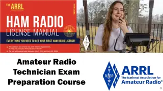
  1. Amateur Radio Technician Exam Preparation Course 1

  2. Amateur Radio Technician Exam Prep Course Module 4 Propagation, Antennas, and Feed Lines 4.1 Propagation 4.2 Antenna and Radio Wave Basics 4.3 Feed Lines and SWR 4.4 Practical Antenna Systems 2 2

  3. Propagation Radio waves propagate in many ways depending on Frequency of the wave Characteristics of the environment We will discuss three basic ways: Line of sight Ground wave Sky wave 3 3

  4. Line of Sight Radio energy can travel in a straight line from a transmitting antenna to a receiving antenna called the direct path There is some attenuation of the signal as the radio wave travels due to spreading out This is the primary propagation mode for VHF and UHF signals Radio waves can be reflected by any sudden change in the path they are traveling, such as a building, hill, or even weather-related changes in the atmosphere Vegetation can also absorb VHF and UHF radio waves Precipitation such as fog and rain can absorb microwave and UHF radio waves although it has little effect at HF and on the lower VHF Bands 4 4

  5. Ground Wave At lower HF frequencies radio waves can follow the Earth s surface These waves will travel beyond the range of line-of-sight Range of a few hundred miles 5 5

  6. Reflect, Refract, Diffract Radio waves are reflected by any conductive surface Ground, water, buildings Refraction or bending occurs when waves encounter a medium having a different speed of light, such as water or an electrical feed line By bending signals slightly back towards the ground, refraction counteracts the curvature of the Earth and allows signals to be received at distances beyond the visual horizon Knife edge diffraction: Diffraction as waves travel past sharp edges of large objects 6 6

  7. Multipath Radio signals arriving at a receiver after taking different paths from the transmitter Results in irregular fading, even when reception is generally good Because dead spots from multipath are usually spaced about - wavelength apart, VHF or UHF signals from a station in motion can take on a rapid variation in strength known as mobile flutter or picket- fencing Distortion caused by multipath can also cause VHF and UHF digital data signals to be received with a higher error rate, even though the signal may be strong 7 7

  8. Tropospheric Propagation Propagation at and above VHF frequencies are assisted by variations in the atmosphere Variations such as weather fronts or temperature inversions create layers of air next to each other that have different characteristics The layers form structures called ducts that can guide even microwave signals for long distances Regularly used by amateurs to make VHF and UHF contacts that would otherwise be impossible by line-of-sight propagation (300 miles or more) 8 8

  9. PRACTICE QUESTIONS 9

  10. Why do VHF signal strengths sometimes vary greatly when the antenna is moved only a few feet? A. The signal path encounters different concentrations of water vapor B. VHF ionospheric propagation is very sensitive to path length C. Multipath propagation cancels or reinforces signals D. All these choices are correct T3A01 C 4-1 10 10

  11. What is the effect of vegetation on UHF and microwave signals? A. Knife-edge diffraction B. Absorption C. Amplification D. Polarization rotation T3A02 B 4-1 11 11

  12. What is the meaning of the term picket fencing? A. Alternating transmissions during a net operation B. Rapid flutter on mobile signals due to multipath propagation C. A type of ground system used with vertical antennas D. Local vs long-distance communications T3A06 B 4-1 12 12

  13. What weather condition might decrease range at microwave frequencies? A. High winds B. Low barometric pressure C. Precipitation D. Colder temperatures T3A07 C 4-1 13 13

  14. What is a likely cause of irregular fading of signals propagated by the ionosphere? A. Frequency shift due to Faraday rotation B. Interference from thunderstorms C. Intermodulation distortion D. Random combining of signals arriving via different paths T3A08 D 4-1 14 14

  15. What effect does multi-path propagation have on data transmissions? A. Transmission rates must be increased by a factor equal to the number of separate paths observed B. Transmission rates must be decreased by a factor equal to the number of separate paths observed C. No significant changes will occur if the signals are transmitted using FM D. Error rates are likely to increase T3A10 D 4-1 15 15

  16. What is the effect of fog and rain on signals in the 10 meter and 6 meter bands? A. Absorption B. There is little effect C. Deflection D. Range increase T3A12 B 4-1 16 16

  17. Which of the following effects may allow radio signals to travel beyond obstructions between the transmitting and receiving stations? A. Knife-edge diffraction B. Faraday rotation C. Quantum tunneling D. Doppler shift T3C05 A 4-1 17 17

  18. What type of propagation is responsible for allowing over-the- horizon VHF and UHF communications to ranges of approximately 300 miles on a regular basis? A. Tropospheric ducting B. D region refraction C. F2 region refraction D. Faraday rotation T3C06 A 4-1 18 18

  19. What causes tropospheric ducting? A. Discharges of lightning during electrical storms B. Sunspots and solar flares C. Updrafts from hurricanes and tornadoes D. Temperature inversions in the atmosphere T3C08 D 4-2 19 19

  20. Why is the radio horizon for VHF and UHF signals more distant than the visual horizon? A. Radio signals move somewhat faster than the speed of light B. Radio waves are not blocked by dust particles C. The atmosphere refracts radio waves slightly D. Radio waves are blocked by dust particles T3C11 C 4-2 20 20

  21. The Ionosphere 30 to 260 miles above Earth s surface Atmosphere thin enough for atoms to be ionized by solar ultraviolet radiation Ions are electrically conductive Because of varying density, the ionosphere forms layers with different amounts of ionization Ionization varies with solar illumination (hourly) and intensity of solar radiation Higher ionization refracts or bends radio waves more strongly 21 21

  22. Ionosphere Layers Layers: D, E, F1 and F2 Depending on whether it is night or day and on the intensity of solar radiation, these layers can refract (E, F1 and F2 layers) or absorb (D and E layers) radio waves Each reflection from the ionosphere is called a hop (can go hundreds or thousands of miles) 22 22

  23. Sunspot Cycle / Activity The level of ionization depends on the intensity of radiation from the Sun Radiation from the Sun varies with the number of sunspots on the Sun s surface High number of sunspots results in high levels of ionizing radiation emitted from the Sun Sunspot activity follows an 11-year cycle Flayers can reflect 6 meter (50 MHz) signals at the sunspot cycle s peak Patches of the E layer can become sufficiently ionized to reflect VHF and UHF signals (called sporadic E) most common during early summer and mid-winter months on 10, 6, and occasionally 2 meters 23 23

  24. The Ionosphere An RF Mirror Ionosphere can refract radio waves back to Earth acts like reflection Most refraction occurs in the F layer Reflection depends on frequency and angle of incidence Too high a frequency or angle and the waves are lost to space Fig 4.2: Signals in the right range of frequencies are refracted back toward the Earth and are received hundreds or thousands of miles away. 24 24

  25. Ionosphere (cont.) The highest frequency signal that can be reflected back to a point on the Earth between the transmitter and receiver is the maximum usable frequency Sky-wave or skip propagation is responsible for most over-the-horizon propagation on HF and low VHF (10 and 6 meters) during peaks of the sunspot cycle Skip is very rare on the 144 MHz and higher UHF bands E region of the ionosphere is also home to meteor trails Bouncing signals off of these ionized trails is called meteor scatter propagation Best band for meteor scatter is 6 meters, and contacts can be made at distances up to 1200 to 1500 miles 25 25

  26. PRACTICE QUESTIONS 26

  27. Which region of the atmosphere can refract or bend HF and VHF radio waves? A. The stratosphere B. The troposphere C. The ionosphere D. The mesosphere T3A11 C 4-3 27 27

  28. Why are simplex UHF signals rarely heard beyond their radio horizon? A. They are too weak to go very far B. FCC regulations prohibit them from going more than 50 miles C. UHF signals are usually not propagated by the ionosphere D. UHF signals are absorbed by the ionospheric D region T3C01 C 4-3 28 28

  29. What is a characteristic of HF communication compared with communications on VHF and higher frequencies? A. HF antennas are generally smaller B. HF accommodates wider bandwidth signals C. Long-distance ionospheric propagation is far more common on HF D. There is less atmospheric interference (static) on HF T3C02 C 4-3 29 29

  30. What is a characteristic of VHF signals received via auroral backscatter? A. They are often received from 10,000 miles or more B. They are distorted and signal strength varies considerably C. They occur only during winter nighttime hours D. They are generally strongest when your antenna is aimed west T3C03 B 4-3 30 30

  31. Which of the following types of propagation is most commonly associated with occasional strong signals on the 10, 6, and 2 meter bands from beyond the radio horizon? A. Backscatter B. Sporadic E C. D region absorption D. Gray-line propagation T3C04 B 4-3 31 31

  32. What band is best suited for communicating via meteor scatter? A. 33 centimeters B. 6 meters C. 2 meters D. 70 centimeters T3C07 B 4-3 32 32

  33. What is generally the best time for long-distance 10 meter band propagation via the F region? A. From dawn to shortly after sunset during periods of high sunspot activity B. From shortly after sunset to dawn during periods of high sunspot activity C. From dawn to shortly after sunset during periods of low sunspot activity D. From shortly after sunset to dawn during periods of low sunspot activity T3C09 A 4-3 33 33

  34. Which of the following bands may provide long-distance communications via the ionosphere s F region during the peak of the sunspot cycle? A. 6 and 10 meters B. 23 centimeters C. 70 centimeters and 1.25 meters D. All these choices are correct T3C10 A 4-3 34 34

  35. Antenna and Radio Wave Basics The antenna system Antenna: Transforms current into radio waves (transmit) and vice versa (receive) Feed line: Connects your station to the antenna Test and matching equipment: Allows you to monitor and optimize antenna system performance For an antenna to do that job efficiently, its dimensions must be an appreciable fraction of the signal s wavelength The radio wave is an electromagnetic wave that contains both electric and magnetic energy or fields created by the RF current The electric and magnetic fields are at right angles to each other and oscillate at the same frequency as the RF current in the antenna 35 35

  36. Antenna Vocabulary Element: The conducting part or parts of an antenna designed to radiate or receive radio waves Driven element: The element supplied directly with power from the transmitter Array: An antenna with more than one element Parasitic element: Elements not connected directly to a feed line Resonant: An antenna is resonant when its feed point impedance has zero reactance Feed point: Where the transmitted energy enters the antenna Radiation: NOT radioactivity! An antenna emitting electromagnetic waves. 36 36

  37. Electromagnetic Waves Radio waves are electromagnetic waves Electric and magnetic fields at right angles to each other, oscillating at the wave s frequency Spread out into space from the antenna Created by AC current Wave and current have the same frequency 37 37

  38. Wave Polarization Refers to the orientation of the radio wave s electric field Vertical or horizontal determined by elements Can be circular if the orientation twists as the wave spreads through space Combinations of polarization are called elliptical polarization (both vertical and horizontal antennas are effective for receiving and transmitting on the HF bands where skip propagation is common) When the polarizations of transmit and receive antennas aren t aligned the same, the received signal can be dramatically reduced (less current is created in the antenna) Summary: Antenna and wave polarization must match for maximum reception 38 38

  39. PRACTICE QUESTIONS 39

  40. What happens when antennas at opposite ends of a VHF or UHF line of sight radio link are not using the same polarization? A. The modulation sidebands might become inverted B. Received signal strength is reduced C. Signals have an echo effect D. Nothing significant will happen T3A04 B 4-5 40 40

  41. Which of the following results from the fact that signals propagated by the ionosphere are elliptically polarized? A. Digital modes are unusable B. Either vertically or horizontally polarized antennas may be used for transmission or reception C. FM voice is unusable D. Both the transmitting and receiving antennas must be of the same polarization T3A09 B 4-5 41 41

  42. What is the relationship between the electric and magnetic fields of an electromagnetic wave? A. They travel at different speeds B. They are in parallel C. They revolve in opposite directions D. They are at right angles T3B01 D 4-5 42 42

  43. What property of a radio wave defines its polarization? A. The orientation of the electric field B. The orientation of the magnetic field C. The ratio of the energy in the magnetic field to the energy in the electric field D. The ratio of the velocity to the wavelength T3B02 A 4-5 43 43

  44. What are the two components of a radio wave? A. Impedance and reactance B. Voltage and current C. Electric and magnetic fields D. Ionizing and non-ionizing radiation T3B03 C 4-5 44 44

  45. Antenna (Some Vocabulary) Gain: Apparent increase in power in a particular direction by focusing radiation in that direction. Measured in decibels (dB). Isotropic: Equal radiation in all directions Omnidirectional: No preferred horizontal direction Directional: Antenna that focuses radiation in specific directions 45 45

  46. Antenna Radiation Patterns 46 46

  47. Antenna Radiation Patterns (cont.) (from previous screen) Radiation patterns are a way of visualizing antenna performance The further the line is from the center of the graph, the stronger the signal at that point Graphs calibrated in dB Most common type of radiation pattern is an azimuthal pattern that shows the antenna s gain in horizontal directions around the antenna An elevation pattern shows the strength of the radiated energy in vertical directions as if the antenna is viewed from the side 47 47

  48. Radiation Pattern Vocabulary Nulls: Directions of minimum gain Lobes: Regions between nulls Main lobe: Lobe with highest gain Side lobe: Any lobe other than the main lobe Forward gain: Gain in the direction assigned as forward Azimuth pattern: Radiation pattern showing gain in all horizontal directions around the antenna Elevation pattern: Radiation pattern showing gain at all vertical angles from the antenna Often restricted to angles above horizontal Front-to-back ratio: Ratio of forward gain to gain in the opposite direction Front-to-side ratio: Ratio of forward gain to gain at right angles to the forward direction 48 48

  49. The Decibel (dB*) A ratio expressed as a power of 10 to make large numbers easier to work with Decibel measures the ratio of two quantities as a power of 10 dB = 10 log (power ratio) dB = 20 log (voltage ratio) Positive values in dB indicate ratios > 1 and negative values of dB are for ratios < 1 Antenna gain is discussed in terms of dB * Pronounced dee-bee 49 49

  50. PRACTICE QUESTIONS 50

More Related Content

giItT1WQy@!-/#giItT1WQy@!-/#giItT1WQy@!-/#giItT1WQy@!-/#