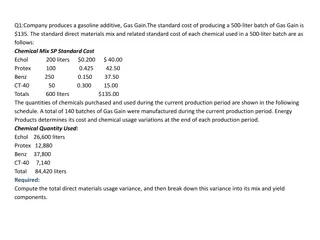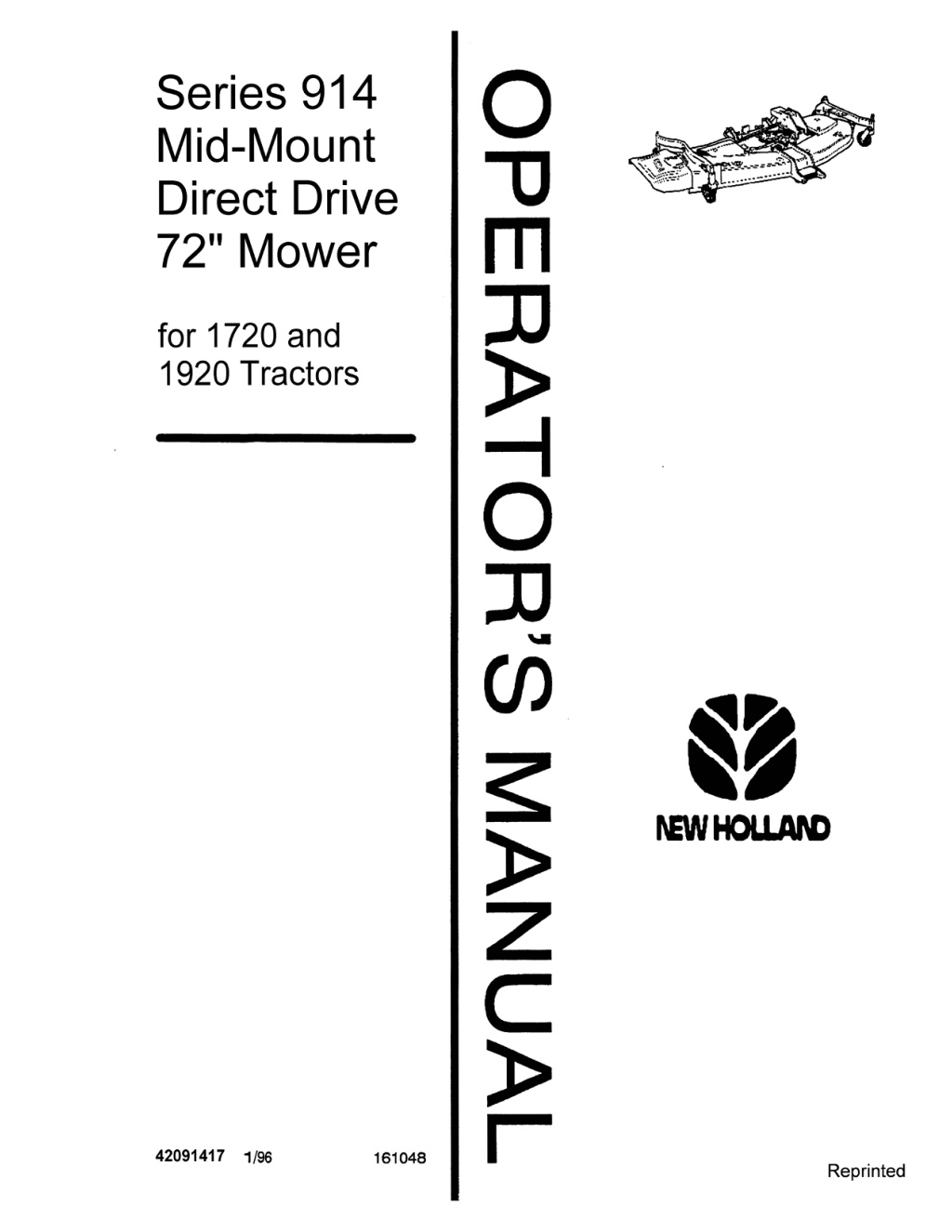
New Holland Series 914 Mid-Mount Direct Drive 72 Mower for 1720 and 1920 Tractors Operator’s Manual Instant Download (Publication No.42091417)
Please open the website below to get the complete manualnn//
Download Presentation

Please find below an Image/Link to download the presentation.
The content on the website is provided AS IS for your information and personal use only. It may not be sold, licensed, or shared on other websites without obtaining consent from the author. Download presentation by click this link. If you encounter any issues during the download, it is possible that the publisher has removed the file from their server.
E N D
Presentation Transcript
o -u m ::D Series 914 Mid-Mount Direct Drive 72" Mower for 1720 and 1920 Tractors o ::D ~ en s:: z c r 42091417 1/96 161048 Reprinted
60 1996 NEW HOLLAND NORTH AMERICA, INC.
INTRODUCTION TO THE OWNER & OPERATOR IDENTIFICATION NUMBERS Congratulations on your decision to purchase a NEW HOLLAND Mower. May we recommend you read this manual before operating your new 914 72 inch Mower. Locate the Serial Number plate and record the numbers from it on the pictured plate below. Always refer to this information when requesting repair parts or dealer service. Your Mower has been designed to give many years of satisfactory service. Successful operation and long life depends on proper maintenance and correct operating technique. lIl\EW HOLLArD _",I' 11;(.1'I1' 0 . , This Operator's Manual has been printed to provide you with safe operating techniques, proper maintenance procedures, correct unit assembly, and parts identification on your Mower. Please read this manual carefully, following all instructions. Keep this manual handy for future reference. I 0 .JI'II:.I.I NEW HOLLAND NORTH AMERICA, WC. MADe: IN U.S.A. All references to right and left, forward or rearward, used in this manual refer to that direction when seated on the tractor seat facing forward. Contact your NEW HOLLAND Dealer for authorized Service Parts. Substitute repair parts will void the product warranty, and will not meet the standards required for safe operation. Should any assistance be required in understanding any section of this manual, contact your NEW HOLLAND Dealer. - 1 -
https://www.ebooklibonline.com Hello dear friend! Thank you very much for reading. Enter the link into your browser. The full manual is available for immediate download. https://www.ebooklibonline.com
TABLE OF CONTENTS 1 INTRODUCTION .......... .......... ...................... ............. ........... ............... ........ To the Owner & Operator ..................................................................... . Identification Numbers ......................................................................... . 4 SAFETY PRECAUTIONS.. .................................... .............. ................... The Mower .............................................................................................. Mower Operation ............................................................................... '" The Tractor ..... .... ........................ ...... ................................. .............. ....... Operating the Tractor & Mower ...... ........ .................... ............. ...... ...... Servicing the Mower.............. ............. ............ ................ ... ................. ... 4 4 4 5 5 6 OPERATING INSTRUCTIONS ............................................................. General Information .......................... .................. ............ ............. ......... Tips for Efficient Mowing ............... .................................. ............ ......... Cutting Heights .......... .......................................... .................................. Uneven Terrain ...................................................................................... Grass Discharge .................................................................................... Mower Transport Lock ................... ................ .............................. ......... 6 6 7 8 8 8 9 REMOVING MOWER FROM TRACTOR .................................. ......... 10 MAINTENANCE SECTION ....... ............. ................ ................................ Lubrication Schedule ............ ........ ................................ .... ............ ....... Blade Removal & Installation ............ ............ ................ .............. ........ Blade Sharpening .. .............. . .................................. ............ .................. Belt Adjustment.... ................ ............ .................. ................ ............ ........ Belt Replacement .. ............... ............. .......... ..... ...................... ............... Spindle Rebuilding ................ .......... .................. ................ ............ ....... Reconditioning the Driveline ............................... ................. .............. Primary (Deck) Gearbox ..... ....... ...................... ................................... Secondary (Rear PTO) Gearbox .................... .............. .............. ........ Driveline Shear Bolt & Snap Ring .. ................ ...................... ............. Seasonal Storage ......................... :........................................................ 1 0 11 11 12 1 2 12 14 14 15 1 7 17 BOLT TORQUE CHART ............ ........... ................................................... 18 Standard Fastener Torques ................................................................ Special Fastener Torques .... ................ ............ .................. ................. 18 1 8 - 2
TABLE OF CONTENTS Continued TROUBLESHOOTING GUIDE .......... ...................................... ................. 20 ASSEMBLY INSTRUCTIONS ......... .......... ........... .................... .............. 22 General Instructions ... ................. ........... ............................. .............. ..... Pre-Assembly Notes .. ................. .......... ............................... ................... Installing Pull Unkage . ................ ..... ....................................... .......... ..... Fastening Mower to Tractor ......... ............ .............................. ................ Installing Secondary Gearbox.... ........................................ .................. Mower Lift Adjustment ................ ............................................ ................ Assembly Notes .......... ................ .......... ............................... ................ .... 22 22 23 26 27 28 28 PARTS ILLUSTRATIONS ......................................................................... 29 Mower Deck Group.... .................... .................... ................................ ...... Mower Drive Group.... ................. ............ .............. ................. ................. Wheel & Strut Group .................. ..... ........................................................ Pull Unk Group .......... ................. ....... .................................... .................. Spring Lift Group ..................................................................................... Pivot Shaft Group ...... ................ ..... ........ ............ ................... .................. Uft Bracket Group...... ................. ........ ................. ................... ................. Control Beam Group .. .................. ........ ................................. .................. Driveline Group ....... .................... ......................... .................. ............ ..... Spindle Group .......... ................... ........ ................................... ............ ..... Primary (Deck) Gearbox Group .... ...................... ................ ................. Secondary (PTO) Gearbox (Front Half) ............................. ................. Secondary (PTO) Gearbox (Rear Half) ............................ ................... 30 32 34 36 36 38 38 40 40 42 44 46 48 SAFETY DECALS ........... ................ ..................................................... ....... 50 5 SPECIRCATIONS ......... .................. .......................................... .................. PRE-DELIVERY CHECKLIST ......... ..... .................. ............. ... ........... ..... 53 NOTES............................................................................................................. 54 OWNER ASSISTANCE.. ................. .......................................................... 56 - 3 -
SAFETY PRECAUTIONS A careful operator is the best operator. Accidents can be avoided by observing certain safety precautions. Read and understand these precautions before operating the Mower. This equipment sh.ould be operated only by those who have been trained in its safe use. THE MOWER y Know and understand all mower instructions and Safety Precautions before assembly, service, or operation. Also read and understand all Safety Precautions in the Tractor Operator's Manual. y Always keep mower discharge directed away from people or animals, which could be injured, and away from objects that could be damaged, by debris thrown by the mowing blades. y Keep the tractor and mower in good operating condition at all times. y To avoid the possibility of injury from flying debris, NEVER operate the mower raised into the transport position. y Always keep all shields and guards securely in place. y Stop and inspect all parts of the mower after striking any foreign object. Repair any damage before resuming mowing operations. y Make sure all fastening hardware is properly tightened before operating the tractor and mower. y Disengage power to the mower and make sure the area behind the tractor and mower is clear before backing up. y Keep all Safety Decals clean and free of dirt and grime. Always replace any Safety Decals that become damaged, lost, painted over, or otherwise become illegible. Replace all Safety Decals when repainting the cutter. y The operator should NEVER leave the tractor seat with the mower blades rotating, with the tractor in motion, or when the tractor engine is running. MOWER OPERATION y Always be alert for vehicle traffic when crossing or mowing near roadways. Avoid bystanders when mowing on or near public facilities. y NEVER operate the mower with the discharge deflector in the raised position. THE TRACTOR y DO NOT permit anyone but the operator to ride on the tractor or mower. There is no safe place on this equipment for passengers. y Always use an approved Roll Over Protective Structure (RaPS) and Seat Belt for safe operation. Overturning a tractor, without a ROPS, can result in serious injury or death. If your tractor is not equipped with a RaPS and Seat 8elt, see your NEW HOLLAND Dealer. y Clear the area of people, pets, and all visible debris before beginning mowing operations. y Mow only during daylight hours, or when the area is well lit artificially. y ALWAYS wear the seat belt on ROPS equipped tractors. DO NOT use a seat belt if the tractor ROPS has been removed. y To avoid loss of control, and to prevent over- turning the tractor and mower, always mow up and down slopes, never across. y NEVER allow an open flame near the fuel tank or tractor battery. y DO NOT operate on steep slopes. y Always slow down when turning. WHEN YOU SEE THIS SYMBOL A IT MEANS: ATTENTION! BECOME ALERT! YOUR SAFETY IS INVOLVED! 4
SAFETY PRECAUTIONS Continued SERVICING THE MOWER v Keep the tractor and mower clean. Grease, dry debris and grass build-up can cause fires, damaging the equipment and causing serious injury to yourself or others. v Check for and replace or repair missing, loose, or damaged parts on the mower. A defective mower could cause injury to another operator who is unaware of a potential problem. v To avoid injury, do not clean, adjust, unclog, or service the mower when the engine is running. v Do not work under the raised tractor or mower deck unless it is securely supported by a hoist, floor jack and jackstands. v Make sure all hoists, floor jacks and jackstands are in good working order and have sufficient capacity to support the elevated equipment, before repair, adjustment, or lubrication of the tractor or mower. v Inspect the mowing blade retainer nuts daily, or whenever a blade has been removed. Torque is 150 ft. Ibs. (204 N m). These nuts have right hand threads. v To avoid injury when handling mowing blades, wear leather gloves, or wrap the blades in the area where they will be held. v Do not modify or alter or permit anyone else to modify or alter the mower, or any of its com- ponents or operating functions. If in doubt on modifications, consult with your NEW HOLLAND Dealer. OPERATING THE TRACTOR & MOWER V Use the handholds and step platforms when mounting and dismounting the tractor to prevent falling. Always keep steps and platforms clean and free of mud or other debris. V The operator MUST remain in the tractor seat, at all times, while mowing, transporting, or anytime the tractor engine is running. V NEVER start the engine while standing beside the tractor. The operator MUST sit in the tractor seat when starting the engine. v NEVER run the engine in a closed building without adequate ventilation. Exhaust fumes are very dangerous and can cause permanent injury or death. v Use extreme care when operating on slopes to maintain equipment stability. v Keep the tractor in gear when traveling downhill. v Install tractor wheel weights to increase stability when operating on slopes. Consult with your NEW HOLLAND Dealer on ballasting requirements for your equipment. v Always bring the tractor to a complete stop, lower the mower deck to ground contact, disengage power to the mower, set the parking brake, shut off the engine and remove the key, before dismounting from the tractor. NEVER park the tractor on an incline. WHEN YOU SEE THIS SYMBOL A IT MEANS: ATTENTION! BECOME ALERT! YOUR SAFETY IS INVOLVEDI 5
OPERATING INSTRUCTIONS GENERAL INFORMATION The safe operation of the Tractor and Mower is the responsibility of the operator. The operator MUST be familiar with tractor and mower controls, how they work, and all Safety Precautions BEFORE starting operation. This mower is designed to be mounted on applicable tractors as a finish cut mower. Mow often! Do not wait for the grass to get too tall. Short grass clippings will disperse better and deteriorate faster. Mowing areas with tall grass or weeds may require cutting at 4-1/2 inches (maximum) height of cut. After mowing once, recut the entire area with the mower reset to the desired final height of cut. A When cutting along sidewalks, driveways, etc., it is advisable to mow with the discharge directed away from them for 2 or 3 passes. This will keep grass clippings off of these areas. A TIPS FOR EFFICIENT MOWING Blade sharpness affects the appearance of the mowed lawn. A dull or damaged blade will cause grass to appear torn or beaten off, rather than cut cleanly. Mowing blades should be checked regularly and kept sharp to insure the best lawn appearance. The gauge wheels on either side of the front of the mowing deck serve as convenient mowings guides. When mowing, position the mower so the gauge wheel overlaps the edge of the strip previously cut. This will assure full mowing coverage. Tractor engine speed while mowing should be at maximum rated RPM. This will insure proper blade speed for effective cutting and discharge of grass clippings. Travel speed greatly effects mowing performance. The operator must use his own best judgement for the ground speed required for encountered mowing conditions. Always use a lower tractor transmission speed for slower mowing, rather than lowering the engine RPM. A When transporting, always disengage the power to the mower. A A - 6 -
OPERATING INSTRUCTIONS - Continued CUTTING HEIGHTS 4. Make sure the gauge wheels are secured with clevis pins and circle clips. This 914 Mower can be adjusted to mow from 1-1/2 inches to 4-1/2 inches (38 to 115 mm) height of cut_ Grass mowing height should be determined by encountered conditions and personal preference. The following recommendations are provided as a guide for cutting height selection. Lawns = 1-1/2" to 3" (38-76 mm) Field Cutting = 3" to 4-1/2" (76-115 mm) To change the height of cut it is necessary to adjust the gauge wheels as follows. GAUGE WHEEL ADJUSTMENT 1. Start the tractor engine and raise the mower by pulling rearward on the hydraulic control lever. GAUGE WHEELS 2. Shut off the engine, remove the key, and set the tractor parking brake. ANTI-SCALP ROLLER 3. After determining the desired cutting height, as shown on the chart below (duplicated as a label on the mower deck), remove the circle clip and clevis pin from the gauge wheel spindle. Place the spindle in line with the appropriate cross hole, reinstall the clevis and circle clip. Repeat on the other gauge wheels. 5. To keep the mower from scalping while cutting on uneven terrain, the front anti-scalp roller is adjustable. Place it in the high position for 1-1/2 and 2 inch mowing, and in the low position for all mowing heights above 2-1/2 inches. FRONT WHEEL ~ : l : : ] L::l1f ~ : ~ t : ~ REAR WHEEL CUTTINO HalOHT Y-E X-C Y-D x y c 1-112- ,Slmm) Y E X C y ., .- (I1mm) ADJUSTING THE ANTI-SCALP ROLLER 1 1/1- ," ... m) ,- (7IIft.) '.112- ,It ... m) 4- (10l1li111) X I y c 6. Lower the mower by pushing the position control lever forward with the engine shut off. X A y X A Y I 4 1/1- (t1lIllm) - 7 -
OPERATING INSTRUCTIONS Continued UNEVEN TERRAIN GRASS DISCHARGE Pre-plan mowing over uneven terrain so the grass will be dry, minimizing wheel slippage and spinning, which will damage the turf. The 914 - 72 inch mower deck has been designed to provide maximum air flow for an even discharge of grass clippings. When mowing tall, or lush grasses, select a lower tractor transmission speed, or reduce the width of cut, for the best discharge efficiency. A Pass diagonally through sharp dips. Avoid sharp drop ofts completely to prevent "hanging-up" the tractor and mower. For the best lawn appearance, do not mow when the grass is wet or heavy with dew. Wet grass could plug the discharge area of the mower, creating an unnatural load through the blades and spindles, possibly damaging the mower deck belt. Wet grass will also leave unsightly clumps on the lawn. A If the mower should become clogged, back the unit out of the uncut grass and try to clear it by engaging and disengaging the PTa with the deck raised. If the mower will not clear itself, raise the deck, shut off the engine, set the parking brake, lock the deck in the transport positopn, and clean the bottom of the deck with a scraper. Before mowing, check the area to determine the best procedure. Consider the grass type and height, and the type of uneven terrain on which the mowing is to take place. A A In medium and heavy cutting conditions, mow so the discharged clippings will be AWAY from uncut grass. In light cutting, discharged clippings can be directed onto the uncut grass, allowing them to be recut finer, leaving the lawn almost free of unsightly clippings. MOWER TRANSPORT LOCK A WARNING: < ALWAY BELT ON ROPSEQUI NOT USE A sEATBETH ROPS HAS liEENREMOVED . .... . Other implements can be used without removing the mower from the tractor, as follows. 1. Disconnect the driveline from the rear gearbox and pull the driveline apart. Fold the front half of the driveline to the right so it lays on the deck top. Strore the rear half in a clean location. Avoid sudden starts and stops while traveling up or down hill, and slow the ground speed while turning. 2. Remove the rear gearbox following instructions on the gearbox decal. . 8
OPERATING INSTRUCTIONS - Continued 3. Start the tractor engine and raise the mower to its full up position. Pull the hairpin clips from the 1/2 inch clevis pins holding the lift locks in their storage positions. See the parts illustration on page 40 for identification. 4. Swing the lift locks up and pin them to the lock sleeves on the rear of the belly bracket as shown_ Use the clevis pin hardware removed above. For mower operation, reverse steps 1 thru 4. Right Side Shown in Locked Position (spring lift linkage removed for photo view of lift lock) REMOVING THE MOWER FROM THE TRACTOR 9. Pull the mower out from under the left side of the tractor, shifting as necessary to guide the gauge wheel spindles and gearbox past tractor com- ponents. Be careful the gauge wheel spindles do not damage the front wheel drive shaft and rubber boot while pulling the mower from under a four wheel drive tractor. 1. Place all mower gauge wheels in their lowest cut (1-1/2") position. Turn and pin the rear wheels in the 900 position. 2. Locate the unit on a smooth hard surface, with the front wheels turned full to the right. Stop the engine, set the parking brake and remove the key. 10. Remove the rear gearbox following instructions on the gearbox decal. 3. Lower the mower deck to the ground and pull the control arm pins, allowing the arms to "break", releaSing pressure from the linkages. 11. On tractors equipped with turf tires, reinstall the left secondary platform step. 4. Pull the lock pin out of the quick attach front linkage and raise the quick attach lever removing the front links from the front bracket. Three point lift implements can now be used without further disassembly of mower attaching parts. 5. Pull the "T" handle at the front of the mower deck, disconnecting the front link assembly. 6. Pull the spring loaded lock pins holding the control arms to the rear of the mower deck. 7. Pin the control beams to the belly brace as shown under Mower Transport Lock on page B. 8. Disconnect the mower driveline from the rear PTO gearbox and swing it forward toward the mower. NOTE: When the mower is removed from the tractor, make sure the driveline does not drag thru dirt or other contaminants. To reinstall the mower, reverse steps 1 thru 11. 9
MAINTENANCE SECTION SCHEDULE Lubrication Gearbox Oil Before operating the 914 - 72 inch mower, make sure it has been properly lubricated according to the illustrated chart below. Both gearbox oil levels should be even with the bottom edge of their filler plug holes. Make sure the mower deck and tractor is level and fill gearboxes with the following pour consistency grease. Always wipe the fitting to be lubricated with a clean cloth before using a grease gun. Dirt injested thru the fitting will damage closely machined parts. NH PIN 9821006 - 1 quart container, or Any "pour consistancyU EP Grease, or Any SAE 80-90W Gear Lube Use an SAE multi-purpose lithium base grease on all lube locations shown. Do not let excess grease build- up on or around parts, especially when the mower is used in sandy areas. I 2 \ 2 Lubrication Intervals Service Intervals REF DESCRIPTION FREQUENCY FREQUENCY DESCRIPTION Blade Spindle (3) Gauge Wheel Axles (4) Front Wheel Pivots (2) Driveline U-Joints (2) and Shaft Half Tube & Spline NS Control Beam to Pivot Shaft (2) NS Rear Gearbox Spindles (2) NS Idler Arm Pivot (1) 1 2 3 4 25 hours 25 hours 25 hours Deck Belt - Check tension weekly, and replace the belt every 200 hours. Blade Retainer Bolts - Daily (See Torque Chart). Both Gearboxes -Check oil level weekly - Drain, flush and change at 200 hour intervals. 25 hours 25 hours 25 hours 200 hours NS = Not Shown - 10-
MAINTENANCE SECTION Continued BLADE REMOVAL & INSTALLATION A WARNING: IfJ!tISED TRAC )t1J ISSECUR FLOOR JACK, Remove mower blades for sharpening and/or for replacement as follows. Remove the mower deck from the tractor, following instructions on page 9. Use a special spanner wrench, PIN FNH24RT96, in the top pulley spokes to hold the spindle shaft while loosening the blade. A blade "stop block" such as the example shown below, can also be used to prevent the blade from turning during loosening or tightening. Maintain Sharp Corner I r Follow Original Pattern C_ 1/32' ~ , / -:;::::;;? / > ___ (; ----======:1 -== Sharpen the blades following the original pattern illustrated above. If using a grinder or grinding disk, use care so the cutting edge does not get too hot from friction, causing it to loose its heat treat. Do not sharpen to a razor edge! Leave a 1/32" edge as shown. STOP BLOCK POSITIONING When installing the blade components, make sure the blade is installed with the curved edge "sail" toward the deck bottom. Check the blade for balance by placing a horizontal rod through the blade center hole. The heavy side of the blade will drop down. Sharpen on the heavy side until the blade remains balanced on the rod. o Using the spanner wrench, torque the blade fasteners to 150 ft. Ibs. (204 Nom). o The top pulley nut torque is 80 ft. Ibs. (109 Nom). BLADE SHARPENING Inspect the blades before each use to be sure they are properly installed and are in good condition. Replace any blade that is bent, excessively nicked or worn, or show signs of other damage. Use only genuine NEW HOLLAND blades on this mower. Balance Rod CHECKING BLADE BALANCE 11
MAINTENANCE SECTION - Continued BELT REPLACEMENT BELT ADJUSTMENT The deck belt is located under two shields on the top of the mower deck. Check and adjust the belt tension after the first 8 hours of mower operation and weekly thereafter. 1. Make sure the tractor is on a firm level surface, the engine is SHUT OFF, the parking brake is SET, and the lift control is in the DOWN position before proceeding. 1. Remove the mower according to instructions on page 9. 2. Remove both belt shields from the top of the mower deck. Loosen and release the threaded spring adjustment rod. NOTE: It is necessary to remove the mower from the tractor for belt work. See instructions on page 9. 3. Remove all four 3/8-16 x 1 bolts and lockwashers from the mower gearbox mount brackets. 2. Remove both belt shields and clean all debris off of the deck, away from the belt and gearbox. Make sure the idler arm and pulleys rotate freely. 4. CAREFULLY roll the belt off of the idler pulley and disconnect the belt from all other pulleys. 5. Install the new belt, reversing steps 2 thru 4, route as illustrated below, and adjust according to instructions in column one. DECK BELT ROUTING DECK BELT SPRING ADJUSTMENT 6. Reinstall both deck shields and reinstall the mower onto the tractor. 3. Loosen the lock nut on the threaded spring adjustment rod. Adjust the spring to 5-9/16 inches (142 mm) overall length between the hook ends. Tighten the lock nut. SPINDLE REBUILDING Reconditioning procedures for all spindles are the same. Make sure the deck, especially the bottom around the spindle, is well cleaned of grass build-up before spindle removal. The spindle to be rebuilt must be removed from the deck. 4. Reinstall both deck shields and reinstall the mower onto the tractor. - 12 -
MAINTENANCE SECTION . Continued DISASSEMBLY 1. Disconnect the belt, remove the blade and pulley nuts, and remove the pulley and blade. 2. Press the lower seal into its bore, seal lip inward, until it bottoms in the housing. Install the seal spacer into the seal. Insert the spindle shaft thru the lower seal and spacer until it is fully in place. A WARNING: < Ifl ? RAISED TR/I/ UNLESS ITI . ... HOIST, FLOq 3. Turn this assembly right side up, holding the shaft so it does not fall out. Slide the bearing spacer over the shaft, into the housing caVity. Install the upper roller bearing cone and the seal spacer on the shaft against the bearing. 2. Remove all four 7/16-20 nuts, from the spindle housing studs, on the top of the deck. Remove the spindle thru the bottom of the deck. 4. Install the upper seal (no seal lip back-up spring) over the shaft and press into place, flush with the housing top. The upper seal lip pOints up (away from the bearing). 3. Disassemble the complete spindle and wash all parts in clean solvent. Inspect and replace any part that is excessively worn or damaged, especially the roller bearing cups and cones. 5. Tap the woodruff key into place in the upper shaft. Wrap masking or electrical tape around the shaft and key. This will keep the key in place and will prevent the shaft from slipping out of the housing during reassembly to the mower deck. Reinstall the lube fitting into the top of the shaft. 4. Carefully inspect the bearing preload spacer from the center of the spindle housing. This spacer is designed to maintain correct preload, without shimming. Its length is specified in the rebuilding instructions that come with the seal kit. REASSEMBLY Make certain all spindle parts are clean before reassembly. All internal parts can be coated with a thin coat of clean multi-purpose grease or lightweight oil for ease of reassembly. 1. Use an arbor press to install the bearing cups into the housing. Make certain the cups are fully seated. Place one roller bearing into the cup in the lower housing. IMPORTANT: upper se81. It can behind the se8/ an upper se8/. MOWER SPINDLE CUTAWAY 7. Place the spindle into the deck from the bottom, and retain with 7/16 lockwashers and 7/16 fine thread locknuts. Torque all four nuts to 35-45 ft. Ibs. (48-61 N m). 13
MAINTENANCE SECTION Continued 8. Remove the tape from the spindle shaft, and while holding the shaft from the bottom, install the belt pulley, 3/4 flat washer and 3/4-16 locknut. 4. Tear down the remaining driveline as necessary. Lay the U-joints aside and wash all other parts in clean solvent. Inspect and replace the U-joints or any other item that is badly worn or damaged. 9. Install the mowing blade, 7/8 flat washer and 7/8- 14 jam nut. REASSEMBLY 10. Torque both spindle nuts using a spanner wrench in the spokes of the pulley. Blade nut torque is 150 ft. Ibs. (204 N m). Pulley nut torque is 80 ft. Ibs. (109 Nom). Retorque these nuts after one hour of mower operation and daily thereafter. Use care when installing the U-joint bearing cups so the needle bearings remain in place. It is advisable to smear a light coating of heavy grease into the cups to help retain the needle bearings. If the cup set, on either side of the cross, will not go in enough for the snap rings to be installed, it usually indicates one or more needles fell and are in the bottom of the cup restricting installation. 11. Lubricate the spindle with a high quality multi- purpose grease until the grease begins to vent from around the UPPER seal. The rebuilt spindle should again be greased after 8 hours of mower operation. Reassembly and reinstallation on the mower is a reverse order of disassembly instructions. RECONDITIONING THE DRIVELINE DISASSEMBLY 1. Disconnect the rear half of the driveline from the tractor PTO shaft, slide it out of the front half and lay it aside. Blind Spline 2. Remove the fastener thru the driveline yoke, and the snap ring from the gearbox shaft, and remove the front half of the driveline from the mower. DECAL & BLIND SPLINE NOTE: There is a blind spline between the rear and front half of the driveline. Align the blind spline on the mower half with tthe arrow decal on the tractor half when putting the shafts together. Install the driveline to the tractor PTO shaft by pulling back on the lock collar as it is installed. Release the lock collar and pull on the shaft to make sure it is locked to the tractor PTO shaft. PRIMARY (Mower) GEARBOX DRIVELINE - Exploded View 3. Clamp the front half yoke securely in a bench vise with jaws that are lined with wood boards, brass or copper faces, etc. Remove the external snap ring from inside the lock collar. Slide the collar and spring off of the yoke. THE LOCK BALLS WILL FALL OUT! Use care so they are not lost. DISASSEMBLY Remove the mower from under the tractor and prepare it for gearbox removal by following all instructions under Belt Replacement on page 12. - 14
Suggest: If the above button click is invalid. Please download this document first, and then click the above link to download the complete manual. Thank you so much for reading
MAINTENANCE SECTION Continued 1. Remove all four bolts retaining the mower gearbox bracket to the top of the deck and remove the gearbox/bracket assembly. 4. Position the gearbox in an upright position, as it will be on the mower, and fill it with grease as shown on the lube schedule on page 10. 2. Drive out the 1/4 roll pin from the offset pulley on the output shaft and remove the pulley. 5. Reinstall the brackets to the gearbox. 6. Install the 8 inch offset pulley to the output shaft on the gearbox and pin in place. Place this gearbox, bracket, and pulley assembly on the mower deck. 3. Remove the brackets from the gearbox. Remove both pipe plugs, lay the box on one side and drain all old oil. Reverse all instructions for Belt Replacement found on page 12 for remaining assembly and mower installation to the tractor. 4. Remove all nine socket head bolts securing the gearbox halves together. Tap the seam with a soft wood or plastic hammer to break the seal. Lay the gearbox on its side and remove the top half. The top half contains thru holes and the vent plug. SECONDARY (Rear PTO) GEARBOX 5. Lift both shafts from the case. ADJUSTMENT 6. Completely disassemble the gearbox, remove all old sealer from both housing halves, wash parts in a clean solvent, and inspect for signs of excessive wear or damage. 1. Disconnect the driveline from the output shaft, pull the clevis pin retaining the gearbox to the drawbar frame, and remove the gearbox. Remove the drain and fill plugs and drain the oil. 2. Remove the cover plate and wash the inside of the gearbox with clean solvent. Inspect the roller chain and sprockets for wear. REASSEMBLY NOTE: Replace bearings, gears, NEW SEALS, retaining rings, etc. See the Parts Illustration Section of this manual for location and sequence of assembly. 3. Adjust the idler as necessary to obtain the dimension shown below. 1. Place both shaft assemblies in the bottom case half, identified by the threaded holes for the nine socket head bolts. Make sure all parts are correctly positioned, especially the seals. The pinion shaft seal must be against the front lip of the casting. 2. Apply a 1/16 Inch (1.6 mm) bead of liquid gasket material (Locktite 504 or 515 or equivalent) to the flat surface of the bottom case half only. 3. Place the case halves together, insert and torque the socket head bolts to 15-20 ft.lbs. (20 27 N m). Lightly tap the shaft ends with a soft hammer to seat the bearings against the retaining rings. NOTE: If wear is apparent, or other damage is noted, proceed to page 16 for rebuilding instructions. Both spindles can be rebuilt following those instructions. - 15
https://www.ebooklibonline.com Hello dear friend! Thank you very much for reading. Enter the link into your browser. The full manual is available for immediate download. https://www.ebooklibonline.com


