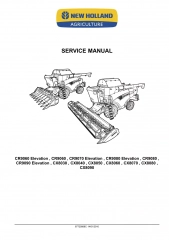
New Holland CR9070 Combine Harvesters Service Repair Manual
To get the complete manual, please open the home page website.nnhttps://www.aservicemanualpdf.com/
Uploaded on | 13 Views
Download Presentation

Please find below an Image/Link to download the presentation.
The content on the website is provided AS IS for your information and personal use only. It may not be sold, licensed, or shared on other websites without obtaining consent from the author. Download presentation by click this link. If you encounter any issues during the download, it is possible that the publisher has removed the file from their server.
E N D
Presentation Transcript
SERVICE MANUAL SERVICE MANUAL CX7080 Elevation / CX7090 Elevation / CX8070 Elevation CX8080 Elevation / CX8090 Elevation CR8070 / CR8080 / CR9070 / CR9080 / CR9090 Combine CX Elevation CR Combine 1/6 Part number 47612507 English March 2014 Part number 47612507 Copyright 2014 CNH Industrial Belgium N.V. All Rights Reserved.
SERVICE MANUAL CR7090 Cursor 9 Tier IVa , CR8070 Combine Tier IV engine MY14 [1940 - ] , CR8070 , CR8080 MY14 CR with tracks [1940 - ] , CR8080 MY14 combine [1940 - ] , CR8080 , CR8090 Cursor 10 Tier IVa , CR8090 Cursor 10 Tier IVa , CR9070 MY14 Combine with tracks [1940 - ] , CR9070 MY14 combine [1940 - ] , CR9080 MY14 combine [1940 - ] , CR9080 MY14 combine with tracks [1940 - ] , CR9080 , CR9090 Cursor 13 Tier IVa , CR9090 Cursor 13 Tier IVa , CR9090 MY14 ZED built combine for NA [1940 - ] , CR9090 MY14 combine [1940 - ] , CR9090 MY14 combine with tracks [1940 - ] , CX7080 Elevation , CX7090 Elevation , CX8070 Elevation , CX8080 Elevation , CX8090 Elevation 47612507 08/04/2014 EN
Link Product / Engine Product Market Product International Region North America Engine CR9080 [1779 - ] CR9080 [Y9G113001 - YAG113831] CR9080 [YAG113901 - ] CR9080 [Y8G112001 - Y9G112788] CR9080 [1779 - ] F3BE0684N*E916 F3BE0684N*E916 North America North America F3BE0684N*E916 F3BE0684N*E916 Latin America F3BE0684N*E916 47612507 08/04/2014
https://www.aservicemanualpdf.com/ My Dear Friend! Thank you very much for visiting. Full manual if required, please enter the following URL into your browser. https://www.aservicemanualpdf.com/
Contents INTRODUCTION Engine....................................................................................... 10 [10.001] Engine and crankcase ............................................................. 10.1 [10.254] Intake and exhaust manifolds and muffler ......................................... 10.2 [10.500] Selective Catalytic Reduction (SCR) exhaust treatment........................... 10.3 [10.400] Engine cooling system ............................................................. 10.4 [10.418] Rotary screen ...................................................................... 10.5 [10.450] Engine air compressor ............................................................. 10.6 Main gearbox and drive............................................................... 14 [14.100] Main gearbox and drive ............................................................ 14.1 Transmission.............................................................................. 21 [21.114] Mechanical transmission ........................................................... 21.1 [21.130] Mechanical transmission external controls......................................... 21.2 [21.145] Gearbox internal components...................................................... 21.3 [21.182] Differential.......................................................................... 21.4 Front axle system ....................................................................... 25 [25.108] Final drive hub, steering knuckles, and shafts ..................................... 25.1 [25.310] Final drives......................................................................... 25.2 Rear axle system........................................................................ 27 [27.124] Final drive hub, steering knuckles, and shafts ..................................... 27.1 Hydrostatic drive......................................................................... 29 [29.100] Transmission and steering hydrostatic control..................................... 29.1 [29.204] Reservoir, cooler, and lines ........................................................ 29.2 [29.218] Pump and motor components...................................................... 29.3 [29.202] Hydrostatic transmission ........................................................... 29.4 [29.300] Rear hydrostatic transmission...................................................... 29.5 47612507 08/04/2014
Brakes and controls .................................................................... 33 [33.202] Hydraulic service brakes ........................................................... 33.1 [33.110] Parking brake or parking lock ...................................................... 33.2 Hydraulic systems....................................................................... 35 [35.000] Hydraulic systems.................................................................. 35.1 [35.300] Reservoir, cooler, and filters........................................................ 35.2 [35.106] Variable displacement pump ....................................................... 35.3 [35.102] Pump control valves................................................................ 35.4 [35.359] Main control valve.................................................................. 35.5 [35.322] Regulated/Low pressure system................................................... 35.6 [35.220] Auxiliary hydraulic pump and lines................................................. 35.7 [35.410] Header or attachment height system .............................................. 35.8 [35.602] Header or attachment leveling system............................................. 35.9 [35.760] Header reverser drive............................................................ 35.10 [35.992] Stone trapping system ........................................................... 35.11 [35.994] Positive Straw Discharge (PSD) ................................................. 35.12 [35.796] Chaff spreader control ........................................................... 35.13 [35.440] Grain tank unload system........................................................ 35.14 [35.450] Traction variator system.......................................................... 35.15 Steering..................................................................................... 41 [41.101] Steering control .................................................................... 41.1 [41.200] Hydraulic control components...................................................... 41.2 [41.432] Autoguidance steering ............................................................. 41.3 Tracks and track suspension........................................................ 48 [48.138] Track rollers ........................................................................ 48.1 [48.130] Track frame and driving wheels.................................................... 48.2 [48.134] Track tension units ................................................................. 48.3 [48.100] Tracks .............................................................................. 48.4 47612507 08/04/2014
Cab climate control..................................................................... 50 [50.100] Heating............................................................................. 50.1 [50.104] Ventilation .......................................................................... 50.2 [50.200] Air conditioning..................................................................... 50.3 Electrical systems....................................................................... 55 [55.000] Electrical system ................................................................... 55.1 [55.100] Harnesses and connectors......................................................... 55.2 [55.201] Engine starting system............................................................. 55.3 [55.301] Alternator........................................................................... 55.4 [55.988] Selective Catalytic Reduction (SCR) electrical system ............................ 55.5 [55.640] Electronic modules................................................................. 55.6 [55.029] Gearbox electric system ........................................................... 55.7 [55.019] Hydrostatic drive control system ................................................... 55.8 [55.512] Cab controls........................................................................ 55.9 [55.051] Cab Heating, Ventilation, and Air-Conditioning (HVAC) controls................. 55.10 [55.050] Heating, Ventilation, and Air-Conditioning (HVAC) control system............... 55.11 [55.662] Header height control ............................................................ 55.12 [55.628] Threshing electrical control ...................................................... 55.13 [55.427] Straw walker variator............................................................. 55.14 [55.426] Harvest material flow control system............................................. 55.15 [55.624] Residue handling control......................................................... 55.16 [55.785] Precision farming system ........................................................ 55.17 [55.911] Global Positioning System (GPS) ................................................ 55.18 [55.680] Autopilot/Autoguidance .......................................................... 55.19 [55.518] Wiper and washer system........................................................ 55.20 [55.404] External lighting .................................................................. 55.21 [55.405] External lighting switches and relays ............................................ 55.22 [55.514] Cab lighting ...................................................................... 55.23 47612507 08/04/2014
[55.408] Warning indicators, alarms, and instruments .................................... 55.24 [55.DTC] FAULT CODES.................................................................. 55.25 Attachments/Headers.................................................................. 58 [58.900] Belt feeding ........................................................................ 58.1 Product feeding.......................................................................... 60 [60.105] Floating roll, feed chain, and drive ................................................. 60.1 [60.110] Feeder housing..................................................................... 60.2 [60.150] Feeder drive system ............................................................... 60.3 [60.165] Feeder reverse system............................................................. 60.4 [60.112] Stone trapping system ............................................................. 60.5 [60.260] Rotor ............................................................................... 60.6 Threshing .................................................................................. 66 [66.000] Threshing .......................................................................... 66.1 [66.260] Threshing mechanism drive system ............................................... 66.2 [66.331] Rotor ............................................................................... 66.3 [66.330] Drum ............................................................................... 66.4 [66.360] Drum/Rotor housing................................................................ 66.5 [66.321] Drum/Rotor variator with electrical control ......................................... 66.6 [66.105] Concave............................................................................ 66.7 [66.101] Concave conveyor plate ........................................................... 66.8 [66.110] Concave control system............................................................ 66.9 Separation................................................................................. 72 [72.350] Beater .............................................................................. 72.1 [72.220] Discharge beater................................................................... 72.2 [72.420] Rotary separator ................................................................... 72.3 [72.440] Straw-flow beater .................................................................. 72.4 [72.110] Straw walker drive system ......................................................... 72.5 [72.101] Straw walkers and shafts .......................................................... 72.6 47612507 08/04/2014
Residue handling........................................................................ 73 [73.300] Positive Straw Discharge (PSD) ................................................... 73.1 [73.230] Straw chopper...................................................................... 73.2 [73.210] Straw chopper drive system........................................................ 73.3 [73.220] Straw chopper frame............................................................... 73.4 [73.335] Chaff spreader ..................................................................... 73.5 [73.410] Opti-Spread system.............................................................. 73.6 Cleaning.................................................................................... 74 [74.000] Cleaning............................................................................ 74.1 [74.101] Cleaning drive systems ............................................................ 74.2 [74.110] Grain pan........................................................................... 74.3 [74.114] Upper shaker shoe ................................................................. 74.4 [74.118] Lower shaker shoe ................................................................. 74.5 [74.125] Clean grain and return cross auger housing ....................................... 74.6 [74.130] Fan housing........................................................................ 74.7 [74.136] Fan drive system................................................................... 74.8 [74.140] Tailings return system.............................................................. 74.9 Crop storage / Unloading............................................................. 80 [80.101] Clean grain elevator................................................................ 80.1 [80.150] Grain tank .......................................................................... 80.2 [80.175] Grain tank unload drive system .................................................... 80.3 [80.180] Grain tank unload .................................................................. 80.4 Accessories ............................................................................... 88 [88.100] Accessories ........................................................................ 88.1 Platform, cab, bodywork, and decals............................................. 90 [90.154] Cab doors and hatches ............................................................ 90.1 [90.110] Operator platform less cab ......................................................... 90.2 [90.118] Protections and footboards......................................................... 90.3 47612507 08/04/2014
[90.124] Pneumatically-adjusted operator seat.............................................. 90.4 [90.105] Machine shields and guards ....................................................... 90.5 47612507 08/04/2014
INTRODUCTION 47612507 08/04/2014 1
INTRODUCTION Foreword WE --- CR Series Tier IV CR8070 [1779 - ] CR8080 [1779 - ] CR9080 [1779 - ] CX7000 Elevation series CX8000 Elevation series WE WE IMPORTANT INFORMATION All repair and maintenance works listed in this manual must be carried out only by staff belonging to the NEW HOL- LAND Service network, strictly complying with the instructions given and using, whenever required, the special tools. Anyone who carries out the above operations without complying with the prescriptions shall be responsible for the subsequent damages. The manufacturer and all the organizations of its distribution chain, including - without limitation - national, regional or local dealers, reject any responsibility for damages due to the anomalous behavior of parts and/or components not approved by the manufacturer himself, including those used for the servicing or repair of the product manufactured or marketed by the Manufacturer. In any case, no warranty is given or attributed on the product manufactured or marketed by the Manufacturer in case of damages due to an anomalous behavior of parts and/or components not approved by the Manufacturer. No reproduction, though partial of text and illustrations allowed 47612507 08/04/2014 3
INTRODUCTION Basic instructions - How to use and navigate through this manual WE --- CR Series Tier IV CR8070 [1779 - ] CR8080 [1779 - ] CR9080 [1779 - ] CX7000 Elevation series CX8000 Elevation series WE WE Technical Information This manual has been produced by a new technical information system. This new system is designed to deliver technical information electronically through Web delivery (eTim), DVD and in paper manuals. A coding system called SAP has been developed to link the technical information to other Product Support functions, e.g., Warranty. Technical information is written to support the maintenance and service of the functions or systems on a customer's machine. When a customer has a concern on his machine it is usually because a function or system on his machine is not working at all, is not working efficiently, or is not responding correctly to his commands. When you refer to the technical information in this manual to resolve that customer's concern, you will find all the information classified using the SAP coding, according to the functions or systems on that machine. Once you have located the technical information for that function or system then you will find all the mechanical, electrical or hydraulic devices, compo- nents, assemblies and sub assemblies for that function or system. You will also find all the types of information that have been written for that function or system, the technical data (specifications), the functional data (how it works), the diagnostic data (fault codes and troubleshooting) and the service data (remove, install adjust, etc.). By integrating SAP coding into technical information, you will be able to search and retrieve just the right piece of technical information you need to resolve that customer's concern on his machine. This is made possible by attaching 3 categories to each piece of technical information during the authoring process. The first category is the Location, the second category is the Information Type and the third category is the Product: LOCATION - is the component or function on the machine, that the piece of technical information is going to describe e.g. Fuel tank. INFORMATION TYPE - is the piece of technical information that has been written for a particular component or function on the machine e.g. Capacity would be a type of Technical Data that would describe the amount of fuel held by the Fuel tank. PRODUCT - is the model for which the piece of technical information is written. Every piece of technical information will have those 3 categories attached to it. You will be able to use any combination of those categories to find the right piece of technical information you need to resolve that customer's concern on his machine. That information could be: the description of how to remove the cylinder head a table of specifications for a hydraulic pump a fault code a troubleshooting table a special tool 47612507 08/04/2014 4
INTRODUCTION How to use this manual This manual is divided into Sections. Each Section is then divided into Chapters. Contents pages are included at the beginning of the manual, then inside every Section and inside every Chapter. An alphabetical Index is included at the end of a Chapter. Page number references are included for every piece of technical information listed in the Chapter Contents or Chapter Index. Each Chapter is divided into four Information types: Technical Data (specifications) for all the mechanical, electrical or hydraulic devices, components and, assemblies. Functional Data (how it works) for all the mechanical, electrical or hydraulic devices, components and assemblies. Diagnostic Data (fault codes, electrical and hydraulic troubleshooting) for all the mechanical, electrical or hydraulic devices, components and assemblies. Service Data (remove disassembly, assemble, install) for all the mechanical, electrical or hydraulic devices, com- ponents and assemblies. Sections Sections are grouped according to the main functions or a systems on the machine. Each Section is identified by a number 00, 35, 55, etc. The amount of Sections included in the manual will depend on the type and function of the machine that the manual is written for. Each Section has a Contents page listed in alphabetic/numeric order. This table illustrates which Sections could be included in a manual for a particular product. PRODUCT Tractors Vehicles with working arms: backhoes, excavators, skid steers, . Combines, forage harvesters, balers, . Seeding, planting, floating, spraying equipment, . Mounted equipment and tools, . SECTION 00 - Maintenance 05 - Machine completion and equipment 10 - Engine 14 - Main gearbox and drive 18 - Clutch 21 - Transmission 23 - Four wheel drive system 25 - Front axle system 27 - Rear axle system 29 - Hydrostatic drive 31 - Implement power take-off 33 - Brakes and controls 35 - Hydraulic systems 36 - Pneumatic system 37 - Hitches, drawbars and implement couplings 39 - Frames and ballasting 41 - Steering 44 - Wheels 46 - Steering clutches 48 - Tracks and track suspension 50 - Cab climate control 55 - Electrical systems 56 - Grape harvester shaking 58 - Attachments/headers 60 - Product feeding 61 - Metering system 62 - Pressing - Bale formation 47612507 08/04/2014 5
INTRODUCTION 63 - Chemical applicators 64 - Chopping 66 - Threshing 68 - Tying/Wrapping/Twisting 69 - Bale wagons 70 - Ejection 71 - Lubrication system 72 - Separation 73 - Residue handling 74 - Cleaning 75 - Soil preparation/Finishing 76 - Secondary cleaning / Destemmer 77 - Seeding 78 - Spraying 79 - Planting 80 - Crop storage / Unloading 82 - Front loader and bucket 83 - Telescopic single arm 84 - Booms, dippers and buckets 86 - Dozer blade and arm 88 - Accessories 89 - Tools 90 - Platform, cab, bodywork and decals 47612507 08/04/2014 6
INTRODUCTION Safety rules WE --- CR Series Tier IV CR series Tier III CX7000 Elevation series CX8000 Elevation series WE WE PRECAUTIONARY STATEMENTS Personal Safety This is the safety alert symbol. It is used to alert you to potential personal injury hazards. Obey all safety messages that follow this symbol to avoid possible injury or death. Throughout this manual and on machine decals, you will find precautionary statements ("DANGER", "WARNING", and "CAUTION") followed by specific instructions. These precautions are intended for the personal safety of you and those working with you. Please take the time to read them. DANGER DANGER indicates a hazardous situation which, if not avoided, will result in death or serious injury. The color associated with Danger is RED. M1169A WARNING WARNING indicates a hazardous situation which, if not avoided, could result in death or serious injury. The color associated with Warning is ORANGE. M1170A CAUTION CAUTION, used with the safety alert symbol, indicates a hazardous situation which, if not avoided, could result in minor or moderate injury. The color associated with Caution is YELLOW. M1171A FAILURE TO FOLLOW "DANGER", "WARNING", AND "CAUTION" INSTRUCTIONS MAY RESULT IN SERIOUS BODILY INJURY, DAMAGE TO HEALTH OR DEATH. NOTICE: Install new decals if the old decals are destroyed, lost painted over or cannot be read. When parts are replaced that have decals make sure you install a new decal with each new part. MACHINE SAFETY NOTICE: The word "notice" is used to inform the reader of something they need to know to prevent minor machine damage if a certain procedure is not followed. The precautionary statements ("Important") is followed by specific instructions. This statement is intended for machine safety. INFORMATION NOTE: Instructions used to identify and present supplementary information. LEGAL OBLIGATIONS This machine may be equipped with special guarding or other devices in compliance with local legislation. Some to these require active use by the operator. Therefor, check local legislations on the usage of this machine. 47612507 08/04/2014 13
SERVICE MANUAL Engine CR7090 Cursor 9 Tier IVa , CR8070 Combine Tier IV engine MY14 [1940 - ] , CR8070 , CR8080 MY14 CR with tracks [1940 - ] , CR8080 MY14 combine [1940 - ] , CR8080 , CR8090 Cursor 10 Tier IVa , CR8090 Cursor 10 Tier IVa , CR9070 MY14 Combine with tracks [1940 - ] , CR9070 MY14 combine [1940 - ] , CR9080 MY14 combine [1940 - ] , CR9080 MY14 combine with tracks [1940 - ] , CR9080 , CR9090 Cursor 13 Tier IVa , CR9090 Cursor 13 Tier IVa , CR9090 MY14 ZED built combine for NA [1940 - ] , CR9090 MY14 combine [1940 - ] , CR9090 MY14 combine with tracks [1940 - ] , CX7080 Elevation , CX7090 Elevation , CX8070 Elevation , CX8080 Elevation , CX8090 Elevation 47612507 08/04/2014 10
Engine - Engine and crankcase Engine - Remove WE --- CR Series Tier IV CR8070 [1779 - ] CX7000 Elevation series CX8000 Elevation series WE WE NOTE: The engine and cooling system used in the combine is designed to be removed as a modular unit. The follow- ing engine removal procedure demonstrates the removal of the engine only from the module. This procedure takes into consideration the possible unavailability of proper, or sufficient lifting equipment for complete module removal. When possible, remove the engine and cooling system module as designed. 1. Remove the gearbox and hydraulic pumps from the en- gine. (Refer to Main gearbox and drive - Remove (14.100)) Place a suitable container (1) below the coolant drain hose (2). NOTE: Depending on model, the cooling system has a coolant capacity between 50 - 60 l (13.2 - 15.9 US gal). Be sure to use clean containers with adequate capacity when draining the cooling system. 1 10013105_780 2. Refer to Expansion tank - Remove (10.400) for the coolant fluid drain and removal of the engine coolant reservoir. NOTE: Depending on the model, the combine engine has an oil capacity between 29 - 35 l (7.7 - 9.2 US gal). Be sure to use clean containers with adequate capacity when draining the engine oil. 3. Remove the cap (1) and turn the engine oil drain valve (2), to the open position. Drain all of the engine oil into suitable containers. 2 10013107 4. Loosen and remove the mounting hardware from the protection cover (1). Remove the cover (1) from the engine compartment. 3 ZEIL09CR0245A0B 47612507 08/04/2014 10.1 [10.001] / 3
Engine - Engine and crankcase 5. Secure the engine cover with an adequate rope. Attach the rope to a lifting device, able to carry the engine cover and stair assembly. Disconnect the shock absorber (1) from the engine cover (2). 4 ZEIL09CR0246A0B 6. Remove the two retaining rings (1), washers (2) and hinge pins (3) from the engine cover. Remove the engine cover from the combine. 5 ZEIL09CR0247A0B 7. Refer to Exhaust muffler - Remove (10.254) for re- moval of the exhaust pipe. 8. Loosen the hardware (1) and remove the support (2). 9. Loosen the clamps (3) from the air inlet pipe (4). Remove the air inlet pipe (4). 6 ZEIL09CR0248A0B 10. Remove the air cleaner assembly, if necessary, refer to Air cleaner - Remove (10.202). 47612507 08/04/2014 10.1 [10.001] / 4
Engine - Engine and crankcase 11. Loosen the clamps (1) and remove the air lines (2). Loosen the clamps (3). Loosen and remove the hardware (4) and remove the air duct (5) from the combine. 7 ZEIL09CR0249A0B Depending on model/options, an additional air tube (7) needs to be removed/disconnected, loosen the coupler (6) from the air compressor. 8 ZEIL09CR0250A0B 12. Loosen the coupler (1) and disconnect the fuel line (2) from the ECU cooler. Loosen the coupler (4) and disconnect the fuel hose towards the injection pump from the fuel line (5). Loosen and remove the clamp (3). 13. Loosen and disconnect the compressed air tube (7) at the connector (6). Loosen and remove the clamp (8). 9 ZEIL09CR0251A0B 14. Loosen the hose clamps (1) and remove the top coolant pipe (2) from the engine and radiator neck. 10 10013111 47612507 08/04/2014 10.1 [10.001] / 5
Engine - Engine and crankcase 15. Loosen the clamps (1) and remove the air pipe (2). 16. Loosen the clamp (3) and disconnect the water hose from the cooling system. 11 ZEIL09CR0252A0B 17. Remove the main drive belt (1) from the engine. 18. Disconnect the electrical connectors (1). ATTENTION: Do not disconnect any of the air conditioning lines or hoses during compressor removal, as serious in- jury could result. 19. Remove the mounting bolts and nuts (2) from the air conditioning compressor (3). Remove the compressor from the engine and tie the assembly out of the way. 12 10013117 20. From inside the grain tank, loosen the mounting nuts on the carriage bolts (1) and turn the rotary screen drive pulley adjusting bolt (2) counter clockwise, to release the tension on the drive belt (3). Remove the drive belt. 13 10013118 47612507 08/04/2014 10.1 [10.001] / 6
Engine - Engine and crankcase 21. From inside the grain tank, loosen the hose clamp (1) and disconnect the lower coolant hose (2) from the engine. 14 10013123 22. Disconnect the main engine electrical harness con- nector (1). 15 10004682 23. If installed, open the rotary screen door and discon- nect the rotary screen brush electrical connector (1). 16 10013132 24. Feedtheconnectorandwireloom(1)andgrommet(2) through the hole in the radiator frame. Secure the wire loom and connector to the engine to prevent damage during removal. NOTE: Removal of the rubber grommet in the radiator frame hole may be necessary to remove the radiator screen brush electrical connector. 17 10013133 47612507 08/04/2014 10.1 [10.001] / 7
Engine - Engine and crankcase 25. Loosen the nut (1) and remove the oil hose (2) from the hose guide (3). 18 10013125 26. Cut the wire ties (1) and separate the engine wire har- ness (2), from the gearbox wire harness (3). Secure each harness to prevent damage during en- gine removal. 19 10013126 27. Loosen the hose clamp (1) and disconnect the rear heater hose (2) from the engine. 20 10013127 28. Loosen the hose clamp (1) and disconnect the front heater hose (2) from the engine. 21 10013128 47612507 08/04/2014 10.1 [10.001] / 8
Engine - Engine and crankcase 29. Remove the nut and bolt (1) from the front engine support bracket (2). 22 10013129 30. Remove the banjo bolt (1) from the engine oil pan (2). Disconnect the oil hoses (3) and plug the hole in the oil pan (2). 23 10010863 31. Loosen and remove the nut (1). Disconnect the main starter cable (2) from the starter solenoid (3). 24 10013130 47612507 08/04/2014 10.1 [10.001] / 9
Engine - Engine and crankcase 32. Attach a suitable chain to the front lift eye (1) and to the ECU bracket (2) at the rear of the engine. 25 20013162 33. Connect the lift chain to a suitable lifting device. Raise the lifting device enough to support the engine during removal of the engine mounting bolts. 26 10013136 34. Loosen the two front, engine mounting bolts (1) and nuts (2) on each side of the engine. Do not remove the mounting bolts at this time. 27 10013137 47612507 08/04/2014 10.1 [10.001] / 10
Engine - Engine and crankcase 35. Loosen the four rear, engine mounting bolts (1) on each side of the engine. Do not remove the mounting bolts at this time. With the engine securely supported by the lifting de- vice, removealloftheenginemountingboltsloosened in the previous steps. Carefully lift the engine from the frame and remove from the combine. 28 10013138 47612507 08/04/2014 10.1 [10.001] / 11
Thank you very much for your reading. Please Click Here. Then Get COMPLETE MANUAL. NO WAITING NOTE: If there is no response to click on the link above, please download the PDF document first and then click on it.
Engine - Engine and crankcase Engine - Install WE --- CR Series Tier IV CR8070 [1779 - ] CX7000 Elevation series CX8000 Elevation series WE WE 1. Attach a suitable chain to the front lift eye (1) at the front of the engine. 1 40015962 2. Attach a suitable chain to the rear lift eye (1) at the rear of the engine. 2 40015963 3. Connect the lift chain to a suitable lifting device. Carefully lift the engine above the combine and lower into position in the frame. 3 10013136_850 47612507 08/04/2014 10.1 [10.001] / 12
Engine - Engine and crankcase 4. Position the engine in the frame, aligning the four front mounting holes. Install the mounting bolts (1). Install the washers and nuts on the bolt. Do not tighten the hardware at this point. 4 40015964 5. Align the rear mounting holes and install the mounting bolts (1) and washer. Tighten and torque the front engine mounting nuts to standard torque. Tighten and torque the rear engine mounting bolts to standard torque. 5 10013138_849 6. Connect the main starter cable (1) to the starter (2). 6 40015961 7. Remove the plug from the oil pan (1) and connect the two oil hoses (2) to the oil pan. Secure with the banjo bolt (3). 7 10010863_851 47612507 08/04/2014 10.1 [10.001] / 13
Engine - Engine and crankcase 8. Secure the gearbox wire harness (1) to the engine wire harness (2) and secure with wire ties. 8 40015960_852 9. Feed the rotary screen brush electrical connector and wire loom (1) and grommet (2) up through the hole in the radiator frame NOTE: Removal of the rubber grommet in the radiator frame hole may be necessary to remove the radiator screen brush electrical connector. 9 10013133_846 10. Connect the rotary screen brush electrical connector (1), and secure the wire loom with wire ties (2). 10 10013132_853 11. Connect the main engine electrical harness connector (1). 11 10004682_854 47612507 08/04/2014 10.1 [10.001] / 14
Engine - Engine and crankcase 12. From inside the grain tank, connect the lower coolant hose (1) to the engine. Secure with the hose clamp (2) and tighten securely. 12 40015959_855 13. Connecttheheaterhoses(1)totheengineandtighten the hose clamps (2) securely. 13 40015959_856 14. From inside the grain tank, install the rotary screen brush drive belt (1) onto the pulley (2) and engine crankshaft pulley. Turn the pulley adjusting bolt (3) clockwise to adjust the belt tension until the belt is tight. Tighten the lock nuts on the carriage bolts (4) when the belt is properly adjusted. 14 40015956_862 15. Install the air conditioning compressor (1) on the en- gine and secure with the mounting bolts (2) Tighten the bolts securely. Connect the electrical connectors (3) to the compres- sor wires. 16. Install the main drive belt onto the engine. 15 40015211_863 47612507 08/04/2014 10.1 [10.001] / 15
Engine - Engine and crankcase 17. Install the air pipe (2) and tighten the clamps (1). 18. Install the water hose and secure the hose with the clamp (3). 16 ZEIL09CR0252A0B 19. Install the top coolant pipe (2) onto the engine and the radiator neck. Tighten the clamps (1). 17 10013111 20. Connect and tighten the compressed air tube (7) at the connector (6). Secure the pipe with the clamp (8). 21. Reconnect the fuel line (2) with the coupler (1) to the ECU cooler. Reconnect the fuel hose towards the injection pump on the fuel line (5) with the coupler (4). Install the clamp (3). 18 ZEIL09CR0251A0B 22. Install the air duct (5) and secure the duct with the hardware (4) and the clamps (3). Install the air lines (2), tighten the clamps (1). 19 ZEIL09CR0249A0B 47612507 08/04/2014 10.1 [10.001] / 16
https://www.aservicemanualpdf.com/ My Dear Friend! Thank you very much for visiting. Full manual if required, please enter the following URL into your browser. https://www.aservicemanualpdf.com/

