John Deere X135R Riding Lawn Tractor Service Repair Manual Instant Download
Please open the website below to get the complete manualnn//
Download Presentation

Please find below an Image/Link to download the presentation.
The content on the website is provided AS IS for your information and personal use only. It may not be sold, licensed, or shared on other websites without obtaining consent from the author. Download presentation by click this link. If you encounter any issues during the download, it is possible that the publisher has removed the file from their server.
E N D
Presentation Transcript
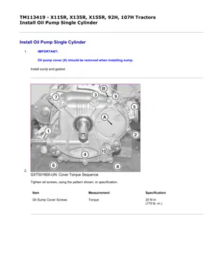
w 1/3(W) TM113419 - X115R, X135R, X155R, 92H, 107H Tractors Install Oil Pump Single Cylinder Install Oil Pump Single Cylinder 1. IMPORTANT: Oil pump cover (A) should be removed when installing sump. Install sump and gasket. 2. GXT001600-UN: Cover Torque Sequence Tighten all screws, using the pattern shown, to specification. Item Measurement Specification Oil Sump Cover Screws Torque 20 N m (175 lb.-in.) file://C:\ProgramData\Service ADVISOR\Temp\TM113419_09001faa82a1b363.html 11/26/2019
w 2/3(W) 3. MXT002447-UN: Oil Pump Cover LEGEND: A - O-ring B - Inner Rotor C - Drive Shaft D - Outer Rotor E - Cover F - Screws Install the oil pump drive shaft (C), ensuring that it engages with camshaft. 4. Lightly coat the rotors with new motor oil. Install the inner (D) then the outer (B) rotor. 5. Insert the O-ring (A) into the O-ring groove in the sump and secure cover (E) with the 3 screws (F). Tighten the screws to specification. Item Measurement Specification Oil Pump Cover Screws Torque 6 N m (50 lb.-in.) 6. Complete installation of remaining governor linkage and carburetor. 7. Adjust governor. (See Governor Static Adjustment and Governor Dynamic Adjustment .) NOTE: Engine oil pressure will vary with oil viscosity, ambient air temperature differences, operating temperatures and engine load. file://C:\ProgramData\Service ADVISOR\Temp\TM113419_09001faa82a1b363.html 11/26/2019
w 3/3(W) 8. Check that engine oil pressure meets specification. Item Measurement Specification Oil pressure Pressure 103 345 kPa (15 50 psi) BS62576,000180F-19-20141114 file://C:\ProgramData\Service ADVISOR\Temp\TM113419_09001faa82a1b363.html 11/26/2019
https://www.ebooklibonline.com Hello dear friend! Thank you very much for reading. Enter the link into your browser. The full manual is available for immediate download. https://www.ebooklibonline.com
w 1/2(W) TM113419 - X115R, X135R, X155R, 92H, 107H Tractors Remove Balance System Single Cylinder Remove Balance System Single Cylinder MXT003049-UN: Crankshaft and Balance System LEGEND: A - Crankshaft B - Counterweight Links C - Alignment Plug D - Counterweight E - Woodruff Key F - Crankshaft Gear 1. Remove crankshaft. 2. Remove the crankshaft gear (F) from the crankshaft (A). If the gear is tight pry it off using two screwdrivers, being careful not to damage the gear. 3. Remove the woodruff key (E) from the crankshaft. 4. Remove and discard the plastic alignment plug (C) from the magneto side of the counterweight (D). Slide the counterweight from the counterweight links (B). 5. Remove the counterweight links from the crankshaft. file://C:\ProgramData\Service ADVISOR\Temp\TM113419_09001faa829c81c6.html 11/26/2019
w 2/2(W) 6. MXT003050-UN: Crankshaft, Links, and Counterweight Check counterweight pins, counterweight link bearing surfaces, and crankshaft eccentric surfaces for wear. 7. If counterweight link bearing surfaces are discolored, scored or worn to or over reject size, the links must be replaced. Item Measurement Specification Balance System Wear Limits Crankshaft Eccentric Journal OD 55.93 mm (2.202 in.) Counterweight Link Bearing ID 56.13 mm (2.210 in.) OUO2003,00000A6-19-20141112 file://C:\ProgramData\Service ADVISOR\Temp\TM113419_09001faa829c81c6.html 11/26/2019
w 1/1(W) TM113419 - X115R, X135R, X155R, 92H, 107H Tractors Install Balance System Single Cylinder Install Balance System Single Cylinder MXT003051-UN: Counterweight Links LEGEND: A - Chamfer 1. Lubricate bearing surfaces with new engine oil. 2. NOTE: Both counterweight links must be installed with the chamfer (A), facing the crankshaft throw. The sides of the link without a chamfer face the outside of the engine. Slide the counterweight links onto the crankshaft eccentrics. 3. Slide the counterweight into the counterweight links. 4. NOTE: The plastic alignment plug aids in the assembly of the counter-weight assembly. Replace this plug whenever it is removed from the counterweight. Press a new plastic alignment plug into the magneto side of the counterweight. 5. Install the woodruff key to the crankshaft. 6. Install the crankshaft gear to the crankshaft. The flange of the gear must face the counterweight link. OUO2003,00000A7-19-20141112 file://C:\ProgramData\Service ADVISOR\Temp\TM113419_09001faa829c81c7.html 11/26/2019
w 1/5(W) TM113419 - X115R, X135R, X155R, 92H, 107H Tractors Inspect Magneto and Cam Bearing Single Cylinder Inspect Magneto and Cam Bearing Single Cylinder MXT003053-UN: Magneto Bearing Measure 1. When checking the main magneto bearing, it should be replaced if scored or if not within specification. Item Measurement Specification Magneto Bearing Wear Limit ID 35.13 mm (1.383 in.) file://C:\ProgramData\Service ADVISOR\Temp\TM113419_09001faa829c81c8.html 11/26/2019
w 2/5(W) 2. MXT003054-UN: Bushing Driver LEGEND: A - Bushing Driver B - Cylinder Block C - Bearing D - Support Place cylinder support (D) under cylinder block (B). Use a bushing driver (A) to press bearing (C) out toward the inside of the block. 3. Lubricate outside surface of bearing and place on inside of block. file://C:\ProgramData\Service ADVISOR\Temp\TM113419_09001faa829c81c8.html 11/26/2019
w 3/5(W) 4. MXT003055-UN: Bearing Install LEGEND: E - Split Line F - Stake Grooves Position bearing with split line (E) away from stake grooves (F). 5. Press bearing in until 2.78 mm (0.109 in.) below surface of block. file://C:\ProgramData\Service ADVISOR\Temp\TM113419_09001faa829c81c8.html 11/26/2019
w 4/5(W) 6. MXT003056-UN: Stake Locations LEGEND: G - Stake Locations Stake new bearing into position at locations shown (G). 7. When installing new magneto side oil seal, properly support cylinder. Press in seal until it is 1.5 mm (0.059 in.) below mounting surface. 8. MXT003057-UN: Cam Gear Bearing file://C:\ProgramData\Service ADVISOR\Temp\TM113419_09001faa829c81c8.html 11/26/2019
w 5/5(W) Measure cam gear bearing. Item Measurement Specification Cam Bearing Wear Limit ID 12.80 mm (0.504 in.) 9. If bearing is worn beyond specification the, cylinder, crankcase cover, or sump must be replaced. OUO2003,00000A8-19-20141112 file://C:\ProgramData\Service ADVISOR\Temp\TM113419_09001faa829c81c8.html 11/26/2019
w 1/1(W) TM113419 - X115R, X135R, X155R, 92H, 107H Tractors Inspect PTO Journal Single Cylinder Inspect PTO Journal Single Cylinder MXT002251-UN: PTO and Cam Bearing 1. From the inside, press the oil seal out of the PTO journal. 2. Inspect PTO bearing and cam bearing. The crankcase cover must be replaced if PTO bearing or cam bearing is scored or if dimensions exceed reject size. Item Measurement Specification PTO Journal and Oil Seal PTO Journal Wear Limit ID 41.37 mm (1.629 in.) Oil Seal Depth Flush 3. Replace the crankcase cover or sump if the journal is worn beyond specification. 4. Support crankcase cover and install new oil seal. Press in seal until it is flush with mounting surface. OUO2003,00000A9-19-20141112 file://C:\ProgramData\Service ADVISOR\Temp\TM113419_09001faa829c81c9.html 11/26/2019
w 1/3(W) TM113419 - X115R, X135R, X155R, 92H, 107H Tractors Inertia Starting Motor Components Single Cylinder Inertia Starting Motor Components Single Cylinder file://C:\ProgramData\Service ADVISOR\Temp\TM113419_09001faa829c81ca.html 11/26/2019
w 2/3(W) file://C:\ProgramData\Service ADVISOR\Temp\TM113419_09001faa829c81ca.html 11/26/2019
w 3/3(W) MXT002890-UN: Starting Motor Components LEGEND: A - C-Ring B - Retainer C - Spring D - Drive Gear E - Helix Starter Clutch F - Wave Washer G - Drive End Head H - Armature I - Through Bolt J - Housing K - Brush Holder L - End Cap OUO2003,00000AA-19-20141112 file://C:\ProgramData\Service ADVISOR\Temp\TM113419_09001faa829c81ca.html 11/26/2019
w 1/6(W) TM113419 - X115R, X135R, X155R, 92H, 107H Tractors Disassemble Inertia Starting Motor Single Cylinder Disassemble Inertia Starting Motor Single Cylinder 1. IMPORTANT: DO NOT clamp motor housing in a vise or strike with a steel hammer. Starting motors contain two powerful magnets that can be broken or cracked if the motor housing is deformed or dented. MXT002259-UN: Starting Motor - Inertia LEGEND: A - Drive End Head B - End Cap C - Bolts Remove pinion gear assembly. 2. Mark drive end head (A) and end cap (B) and housing using a marker. This will assure proper orientation of the drive end head and end cap when assembling starter. 3. Remove bolts (C) and inspect bushing for wear. If worn, replace drive head end assembly. file://C:\ProgramData\Service ADVISOR\Temp\TM113419_09001faa829c81cb.html 11/26/2019
w 2/6(W) 4. MXT002260-UN: Armature and Housing Hold the armature and bearing end cap against a work surface while sliding housing off the armature. (This allows the armature to remain in the bearing end cap and brush holder for inspection of brush contact to armature.) file://C:\ProgramData\Service ADVISOR\Temp\TM113419_09001faa829c81cb.html 11/26/2019
w 3/6(W) 5. MXT002261-UN: Armature and Brush Holder LEGEND: B - End Cap D - Brush Holder E - Armature While holding brush holder (D) and armature (E), remove bearing end cap (B) from armature. 6. IMPORTANT: DO NOT use emery cloth to clean the commutator. The particles from the cloth will become embedded in the commutator and cause rapid brush wear. file://C:\ProgramData\Service ADVISOR\Temp\TM113419_09001faa829c81cb.html 11/26/2019
w 4/6(W) MXT002262-UN: Armature and Brush Holder LEGEND: D - Brush Holder E - Armature Remove brush holder (D) from armature commutator (E). 7. NOTE: The bearing housing and armature should not be soaked in a cleaning solution. Fine sandpaper, such as crocus cloth, can be used to clean the armature. The commutator may also be machined with the use of a diamond cutting tool to no less than 31.24 mm (1.23 in.) outside diameter. file://C:\ProgramData\Service ADVISOR\Temp\TM113419_09001faa829c81cb.html 11/26/2019
w 5/6(W) MXT002263-UN: Commutator Slots between the commutator bars should be cleaned as shown using a broken piece of hacksaw blade. 8. If it is suspected that the armature field coil, magnets or motor housing is defective, a new part should be tried in the motor. If proper testing equipment is available, check the suspected armature or field coil to determine if it is defective (opens or grounds). file://C:\ProgramData\Service ADVISOR\Temp\TM113419_09001faa829c81cb.html 11/26/2019
w 6/6(W) 9. MXT002264-UN: Starting Motor Brushes LEGEND: F - Brushes G - New Length H - Worn Length The brushes (F) should be checked for proper seating, weak brush springs, dirt, oil or corrosion. 10. Comparing to normal length when new (H), if brushes are worn to 3.2 mm (0.125 in.) (G), replace brushes. When all parts have been thoroughly cleaned, lightly lubricate the bearings. Item Measurement Specification Starter (Inertia) Minimum Brush Length 3.2 mm (0.125 in.) OUO2003,00000AB-19-20141112 file://C:\ProgramData\Service ADVISOR\Temp\TM113419_09001faa829c81cb.html 11/26/2019
w 1/6(W) TM113419 - X115R, X135R, X155R, 92H, 107H Tractors Assemble Inertia Starting Motor Single Cylinder Assemble Inertia Starting Motor Single Cylinder MXT002265-UN: Brush Retainers LEGEND: A - Retainers 1. NOTE: Brush retainers (A) can be made from standard size paperclips. Straighten and cut to length 2-1/2 in. Bend into a U-shape with sides of 1 in. and bottom 1/2 in. in length. Place brushes in their slots and hold brushes with retainers. file://C:\ProgramData\Service ADVISOR\Temp\TM113419_09001faa829c81cc.html 11/26/2019
w 2/6(W) 2. MXT002266-UN: Armature and Brush Holder Place armature commutator in brush holder and remove brush retainers. file://C:\ProgramData\Service ADVISOR\Temp\TM113419_09001faa829c81cc.html 11/26/2019
w 3/6(W) 3. MXT002267-UN: Armature and End Plate Install bearing end plate on armature commutator journal making sure plate indexes with brush holder. file://C:\ProgramData\Service ADVISOR\Temp\TM113419_09001faa829c81cc.html 11/26/2019
w 4/6(W) 4. MXT002268-UN: Starting Motor Housing LEGEND: B - Notch Slide motor housing over armature with the notch (B) toward brush holder. file://C:\ProgramData\Service ADVISOR\Temp\TM113419_09001faa829c81cc.html 11/26/2019
Suggest: If the above button click is invalid. Please download this document first, and then click the above link to download the complete manual. Thank you so much for reading
w 5/6(W) 5. MXT002269-UN: Starting Motor - Inertia Washers Place wave washer on armature shaft with concave side up. Then place flat washer on armature. 6. Place drive end cap on starting motor housing making sure that marks on drive end head and end cap line up with housing mark. file://C:\ProgramData\Service ADVISOR\Temp\TM113419_09001faa829c81cc.html 11/26/2019
https://www.ebooklibonline.com Hello dear friend! Thank you very much for reading. Enter the link into your browser. The full manual is available for immediate download. https://www.ebooklibonline.com

