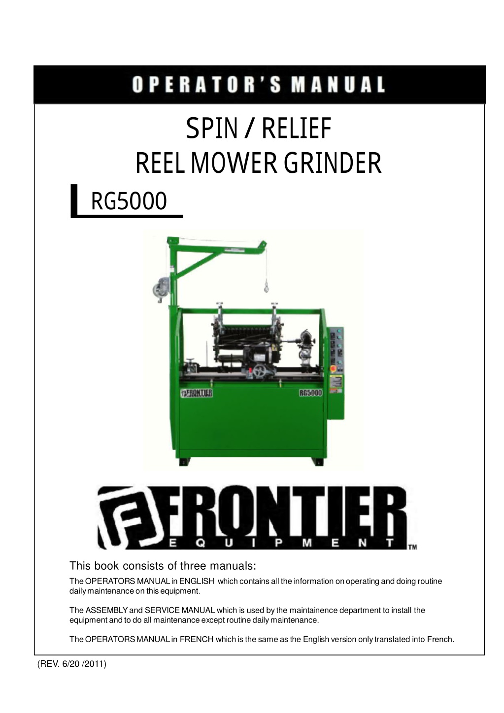
John Deere RG5000 SpinRelief Reel Mower Grinder Operator’s Manual Instant Download (Publication No. 5NTRG5007903)
Please open the website below to get the complete manualnn// n
Download Presentation

Please find below an Image/Link to download the presentation.
The content on the website is provided AS IS for your information and personal use only. It may not be sold, licensed, or shared on other websites without obtaining consent from the author. Download presentation by click this link. If you encounter any issues during the download, it is possible that the publisher has removed the file from their server.
E N D
Presentation Transcript
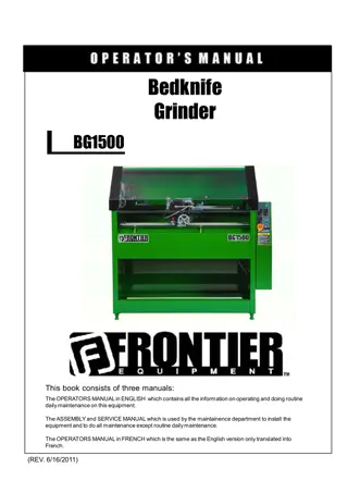
SPIN / RELIEF REEL MOWER GRIN DER RG5000 This book consists of three manuals: TheOPERATORS MANUAL in ENGLISH which contains all the information on operating and doing routine daily maintenance on thisequipment. The ASSEMBLYand SERVICE MANUAL which is used bythe maintainence department to install the equipment and to do all maintenance except routine daily maintenance. TheOPERATORSMANUALin FRENCH which is the same as the English version only translated into French. 1 (REV. 6/20 /2011)
DEALER PREPARATION/INSTALLATION CHECK LIST Frontier RG5000 Spin/Relief Reel Mower Grinder THIS CHECKLIST IS TO REMAIN IN OWNER S MANUAL It is the responsibility of the dealer to complete the procedures listed below, then review this checklist with the customer upon the delivery or the sale of this equipment.The installation training goes over the basic operational functions of the equipment. To ensure adequate training, we require that the following items are reviewed by your John Deere Dealer. Please check off to ensure that you understand the following items before the installation training is complete: 7. Review proper positioning of reel 8. Explain use of reel grinder relief mechanism 9. Review traverse proximity switch positioning 10. Explain use of reel grinder alignment gage 11. Explain reel grinder spin speed vs. quality 12. Discuss reel grinder set-up chart in manual 13. Review General Maintenance 1. Equipment is completely assembled 2. All shields are in place and in good condition. 3. All decals in place and readable. 4. Overall condition good (i.e. paint, welds, electrical) 5. Verify there is sufficient electrical power to operate the machine. 6. Review Operators, Assembly & Service Manuals, and any additional training material if available. Dealer's Signature Purchaser's Signature Safety IMPORTANT SAFETY MESSAGE FOR OWNERS/OPERATORS OF REEL GRINDERS Before operating a reel grinder, an operator must read and understand all of the information in the owner s manual and in the safety signs attached to the product. A person who has not read or understood the owner s manual and safety signs is not qualified to operate the unit. Accidents occur often on machines that are used by someone who has not read the owner s manual and is not familiar with the equipment. If you do not have an owner s manual or current production safety signs, contact the manufacturer or your dealer immediately. Safety is a primary concern in the design, manufacture, sale, and use of reel grinders. As manufacturers of reel grinders, we want to confirm to you, our customers, our concern for safety. We also want to remind you about the simple, basic, and common sense rules of safety when using a reel grinder. Failure to follow these rules can result in severe injury or death to operators or bystanders. It is essential that everyone involved in the assembly, operation, transport, maintenance, and storage of this equipment be aware, concerned, prudent, and properly trained in safety. Always use proper shielding as specified by the manufacturer. Reel grinders are designed for one-man operation. Never operate the grinder with anyone near, or in contact with, any part of the grinder. Be sure no one else, including bystanders, is near you when you operate this product. Our current production machines include, as standard equipment, guards or shields for the grinding wheel, safety signs and an operators manuals. Never bypass or operate the machine with any of the guards or safety device removed. Following these simple, basic safety rules, as well as others identified in the owner s manual and in product safety signs, will help minimize the possibility of accidents and increase your productivity in using this product. Be careful and make sure that everyone who operates the grinder knows and understands that it is a very powerful piece of machinery, and if used improperly, serious injury or death may result. The final responsibility for safety rests with the operator of this machine. Read and fully understand all the safety practices discussed on pages 4 and 5 of this manual. All safety rules must be understood and followed by anyone who works with reel grinders. 2
TO THE DEALER: Assembly and proper installation of this product is the responsibility of the John Deere dealer. Read manual instructions and safety rules. Make sure all items on the Preparation Check List in the Operator s Manual are completed before releasing equipment to the owner. TO THE OWNER: Read this manual before operating your Frontier equipment. Keep this manual handy for ready reference. Require all operators to read this manual carefully and become acquainted with all adjustments and operat- ing procedures before attempting to operate the equipment. Replacement manuals can be obtained from your selling dealer. The equipment you have purchased has been carefully engineered and manufactured to provide depend- able and satisfactory use. Like all mechanical products, it will require cleaning and upkeep. Lubricate the unit as specified. Please observe all safety information in this manual and safety decals on the equipment. For service, your authorized John Deere dealer has trained mechanics, genuine Frontier service parts, and the necessary tools and equipment to handle all ofyour service needs. Use only genuine Frontier service parts. 3
https://www.ebooklibonline.com Hello dear friend! Thank you very much for reading. Enter the link into your browser. The full manual is available for immediate download. https://www.ebooklibonline.com
SAFETY INSTRUCTIONS ! Safety Awareness Symbols are inserted into this manual to alert you to possible Safety Hazards. Whenever you see these symbols, follow their instructions. The Warning Symbol identifies special instructions or procedures which, if not correctly followed, could result in personal injury. The Caution Symbol identifies special instructions or procedures which, if not strictly observed, could result in damage to or destruction of equipment. 1. KEEP GUARDS IN PLACE and in working order. 12. DON'T OVERREACH. Keep proper footing and balance at all times. 2. REMOVE WRENCHES AND OTHER TOOLS. 13.MAINTAIN GRINDER WITH CARE. Follow instructions in Service Manual for lubrication and preventive maintenance. 3. KEEP WORK AREA CLEAN. 14.DISCONNECT POWER BEFORE SERVICING, or when changing the grinding wheel. 4. DON'T USE IN DANGEROUS ENVIRONMENT. Don't use Grinder in damp or wet locations. Machine is for indoor use only. Keep work area well lit. 15.REDUCE THE RISK OF UNINTENTIONAL STARTING. Make sure all switches are OFF before plugging in the grinder. 5. KEEP ALL VISITORS AWAY. All visitors should be kept a safe distance from work area. 16.USE RECOMMENDED ACCESSORIES. Consult the manual for recommended accessories. Using improper accessories may cause risk of personal injury. 6. MAKE WORK AREA CHILD-PROOF with padlocks or master switches. 7. DON'T FORCE THE GRINDER. It will do the job better and safer if used as specified in this manual. 17.CHECK DAMAGED PARTS. A guard or other part that is damaged or will not perform its intended function should be properly repaired or replaced. 8. USE THE RIGHT TOOL. Don't force the grinder or an attachment to do a job for which it was not designed. 18.KNOW YOUR EQUIPMENT. Read this manual carefully. Learn its application and limitations as well as specific potential hazards. 9. WEAR PROPER APPAREL. Wear no loose clothing, gloves, neckties, or jewelry which may get caught in moving parts. Nonslip footwear is recommended. Wear protective hair covering to contain long hair. 19.KEEP ALL SAFETY DECALS CLEAN AND LEGIBLE. If safety decals become damaged or illegible for any reason, replace immediately. Refer to replacement parts illustrations in Service Manual for the proper location and part numbers of safety decals. 10. ALWAYS USE SAFETY GLASSES. 11. SECURE YOUR WORK. Make certain that the cutting unit is securely fastened with the clamps provided before operating. 20.DO NOT OPERATE THE GRINDER WHEN UNDER THE INFLUENCE OF DRUGS, ALCOHOL, OR MEDICATION. 4
SAFETY INSTRUCTIONS ! IMPROPER USE OF GRINDING WHEEL MAY CAUSE BREAKAGE AND SERIOUS INJURY. Grinding is a safe operation if the few basic rules listed below are followed. These rules are based on material contained in the ANSI B7.1 Safety Code for "Use, Care and Protection of Abrasive Wheels". For your safety, we suggest you benefit from the experience of others and follow these rules. DO DON'T 1. DO always HANDLE AND STORE wheels in a careful manner. 1. DON'T use a cracked wheel or one that HAS BEEN DROPPED or has become damaged. 2. DO VISUALLY INSPECT all wheels before mounting for possible damage. 2. DON'T FORCE a wheel onto the machine OR ALTER the size of the mounting hole--if the wheel won't fit the machine, get one that will. 3. DO CHECK MACHINE SPEED against the established maximum safe operating speed marked on wheel. 3. DON'T ever EXCEED MAXIMUM OPERATING SPEED established for the wheel. 4. DO CHECK MOUNTING FLANGES for equal and correct diameter. 4. DON'T use mounting flanges on which the bearing surfaces ARE NOT CLEAN, FLAT AND FREE OF BURRS. 5. DO USE MOUNTING BLOTTERS when supplied with wheels. 5. DON'T TIGHTEN the mounting nut EXCESSIVELY. 6. DO be sure WORK REST is properly adjusted. 6. DON'T grind on the SIDE OF THE WHEEL (see Safety Code B7.2 for exception). 7. DO always USE A SAFETY GUARD COVERING at least one-half of the grinding wheel. 7. DON'T start the machine until the WHEEL GUARD IS IN PLACE. 8. DO allow NEWLY MOUNTED WHEELS to run at operating speed, with guard in place, for at least one minute before grinding. 8. DON'T JAM work into the wheel. 9. DON'T STAND DIRECTLY IN FRONT of a grinding wheel whenever a grinder is started. 9. DO always WEAR SAFETY GLASSES or some type of eye protection when grinding. 10. DON'T FORCE GRINDING so that motor slows noticeably or work gets hot. AVOID INHALATION OF DUST generated by grinding and cutting operations. Exposure to dust may cause respiratory ailments. Use approved NIOSH or MSHA respirators, safety glasses or face shields, and protective clothing. Provide adequate ventilation to eliminate dust, or to maintain dust level below the Threshold Limit Value for nuisance dust as classified by OSHA. 5
TABLE OF CONTENTS This machine is intended fo grinding the reel of reel type mower units ONLY. Any use other than this may cause personal injury and void the warranty. ! To assure the quality and safety of your machine and to maintain the warranty, you MUST use original equipment manufactures replacement parts and have any repair work done by a qualified professional. ALL operators of this equipment must be thoroughly trained BEFORE operating the equipment. Do not use compressed air to clean grinding dust from the machine. This dust can cause personal injury as well as damage to the grinder. LOW VOLTAGE RELAY The grinder is equipped with a high-low voltage relay which is factory preset at 100-140 VAC. If the power supply line does not deliver 100-140 VAC power under load, the relay will open and trip out the starter. If this occurs, your power supply line is incorrect and must be correct before proceeding further with the grinder. TABLE OF CONTENTS Safety Instructions ................................................................................................................Page 4 - 7 Daily Maintenance ................................................................................................................Page 6 Getting to Know Your Grinder ................................................................................................Page 8 - 15 Operating Instructions ..........................................................................................................Page 16 - 38 Reel Setup Chart..................................................................................................................Page 39 DAILY MAINTENANCE BY THE OPERATOR On a daily basis, clean the grinder by wiping it off. On a daily basis, remove all grinding grit from the grinding head and traverse rail areas. On a daily basis, inspect the grinder for loose fasteners or components and tighten. Contact your company's Maintenance Department if damaged or defective parts are found. ! DO NOT USE COMPRESSED AIR TO CLEAN GRINDING DUST FROM THE GRINDER. 6
SAFETY INSTRUCTIONS PLEASE TAKE SPECIAL NOTE OF THE FOLLOWING WARNING DECALS LOCATED ON THE GRINDER. BOOM CAPACITY GRINDING WHEEL RPM SHARP OBJECTS ELECTRICITY GENERAL INFORMATION NO FLAMMABLES Label Sheet (English and Spanish) Part Number 5NT118301 (English and French) Part Number 5NT118302 7
GETTING TO KNOW YOUR GRINDER FIG. 1 SPECIFICATIONS Solid state, non-contacting proximity switches. 67" [170 cm] 58" [147 cm] Machine, 83" [211 cm] Boom 42" [107 cm] 817 lbs [371 kg] Machine Weight, 1000 lbs. [454 kg] Shipping Weight Precision heavy duty reinforced welded steel base Precision Ground, Hardened Steel - 1.000" Dia. [25.4 mm] 1HP AC Motor, 3450 RPM .20 HP Fan Cooled Variable Speed DC Motor More than 75 Dba, Less than 95 Dba Belt driven with easy to engage clamp system Overhead boom with 400 lbs [180kg] capacity Traversing Switches Overall Width Overall Height Overall Depth Weight Base Construction Carriage Rails Grind Head Motor Spin Motor Sound Level Auto Traverse Elevator Control System *Reversible Spin drive for variable speed Spin or variable torque relief functions *Variable speed traverse control. Options: *Greensmower Mouting Bracket Assembly *Pull Gang Mounting Kit 8
GETTING TO KNOW YOUR GRINDER (Continued) CONTROL PANEL COMPONENT IDENTIFICATION Review the following control panel component descriptions before proceeding with the instructions FIG. 2 SYSTEM START PUSHBUTTON The green pushbutton is the system start switch. Pushing it will engage the magnetic starter and power the control panel. The magnetic starter will not engage unless the emergency stop pushbutton is pulled out and the grinding motor switch and spin motor switch are turned off. GRIND SELECTOR SWITCH Variable speed spin Switch must be up to perform spin grinding operations. Variable Torque Relief Switch must be down to perform relief grinding operations. SPIN DRIVE ROTATION SWITCH Forward / Off / Reverse This switch reverses the direction of the spin drive motor. IMPORTANT: Because the spin drive motor can be flipped, the direction may be opposite of what is shown on the decal. SPIN SPEED POTENTIOMETER DIAL RPM Adjusts the speed of reel rotation when you have the grind selector switch set at variable speed spin. 9
GETTING TO KNOW YOUR GRINDER (Continued) PUSH-PULL EMERGENCY STOP BUTTON Push in to cut all power to the control panel functions. This removes power from all motors, including the grinding motor, traverse motor, spin motor, etc. To restore power, pull up on button and press the Start button. SPIN MOTOR SWITCH On / Off Turn the Spin Motor on and off. RELIEF TORQUE DIAL Adjusts the Spin Drive Motor torque (the torque holding the reel blade to the relief finger) when Grind Selector Switch is set at variable Torque Relief. GRINDING WHEEL MOTOR SWITCH On / Off Turn the Grinding Wheel Motor on and off. TRAVERSE MOTOR SWITCH Turns the traverse drive motor ON/OFF. TRAVERSE SPEED POTENTIOM- ETER DIAL - FT / MIN Adjusts the speed of the left & right movement of the Grinding wheel. 10
GETTING TO KNOW YOUR GRINDER (Continued) OVERHEAD MOWER CLAMP ASSEMBLY CLAMP ROD LOCK KNOB ASSEMBLY LONG THREADED KNOB ASSEMBLY BAR CLAMP TOP Each overhead mower clamp assembly consists of two rectangular bar clamps (top and bottom), which also contain the adjustable holding fixtures. These clamps will be positioned on the overhead square bar as shown in FIG. 3 and FIG 4. They are designed to lock into place and not move during the grinding procedure. The holding fixtures can be clamped to the front roller or another part of the mowing unit. The release pin allows for quick mounting of the reel. Pull out to the release pin rotate the C-Clamp out of way when mounting. Their are two mounting holes for the release pin, a vertical position and one where the clamp is tipped back approximately 8 degrees. Use the vertical position unless there is a clearance issue then use the tipped position. BAR CLAMP BOTTOM HOLDING FIXTURE FIG. 3 RELEASE PIN CLAMP ROD The is also a set of rods with a flat plate. Use these rods if you are bolting directly to the frame. Insert a bolt through one of the holes in the plate and tighten to a hole or thread in the cutting unit frame. See FIG 4. FIG. 4 ROLLER SUPPORTS There are two roller supports that are mounted to the square mounting bar. Typically they will be mounted so that the "V" faces up with the offset toward the back of the machine. See FIG 5. If necessary they may be mounted with the offset toward the front of the machine or the "V" facing the back of the machine and the offset mounted high or low depending on the reel type. ! THE HAND KNOBS ON THE SQUARE BAR MUST BE VERY TIGHT OR THE REEL CAN LOOSEN CAUSING POOR GRIND QUALITY. FIG. 5 11
GETTING TO KNOW YOUR GRINDER (Continued) CENTER MOUNTING BRACKETS The centers mounting brackets consist of a stationary center bracket and an adjustable center bracket. The stationary bracket will normally be used on the left hand side of the mounting bar when facing the reel loading position. See FIG.6. The centering fixtures are used primarily on greens mowers. FIG. 6 OPTIONAL PULL GANG BRACKETS The OPTIONAL Pull Gang Reel Mount Kit 5NT18574 consists of a lower mounting bracket that fits over the square tooling mounting bar and two threaded locking screws. Attached to this is the upper "V" bracket that cradle the reel hub when in position. There are three vertical adjustments on this fixture. The fixture will normally be used in the upper hole position. See FIG. 7. FIG. 7 These brackets can be mounted on the square mounting bar with offset either forward or backwards, but the normal position will be with the "V" centered over the bar or with the offset facing the back of the machine. The hold-down swing arm has an upper and lower mounting position depending on mower hub size. The rear roller of the pull gang mowing unit attaches to the roller supports as shown in FIG. 8. VICE GRIP CHAIN CLAMP FIG. 8 12
GETTING TO KNOW YOUR GRINDER (Continued) TRAVERSE ACTUATOR RELEASE The belt that drives the grinding carriage left and right can be released to allow manual movement of the grinding carriage. The Traverse Engagement Lever is located at the front of the carriage to the left of the infeed handwheel. See FIG. 9. Rotate the release arm up to release the belt and rotate the release arm down to engage belt. FIG. 9 TRAVERSE BELT TRAVERSE ENGAGEMENT LEVER PROXIMITY SENSORS This Grinder is equipped with proximity sensors to limit the travel of the grinding head. When activated the proximity sensors will change the direction of the grinding head. Adjust the position by sliding them along the rail. See FIG. 10. FIG. 10 PROXIMITY SENSOR 13
GETTING TO KNOW YOUR GRINDER (Continued) GRINDING WHEEL AND GUARD FOR SPIN GRINDING Spin grinding requires a 1.00" wide [25.4 mm] grinding wheel and the flat grinding wheel guard. See FIG. 11. GRINDING WHEEL AND FINGER - GUARD ASSEMBLY FOR RELIEF GRINDING FIG. 11 Relief grinding requires a 3/8" .375" [9.5 mm] grinding wheel. Use the wheel guard with the fixed relief finger and the moveable index finger. See FIG. 12. RELIEF GRINDING FINGER ADJUSTMENTS The relief Index Finger Assembly has three adjustments: FIG. 12 1. The position of the index pin is can be adjusted by loosening the its locking setscrew. The height of the finger may need to be raised to catch the next blade on small diameter reels or it may need to be lowered to avoid interference with the reel spider. See FIG. 13. INDEX PIN LOCKING SETSCREW FIG. 13 2. Use the travel limit knob to adjust the stop position of the moveable finger. The moveable finger stop needs to be adjusted so that the reel blade makes a smooth transition from the index pin onto the fixed finger. See FIG. 14. ! MOVEABLE FINGER FIXED FINGER WHEN GRINDING THE REEL BLADE SHOULD BE SUPPORTED BY THE FIXED FINGER NOT THE MOVEABLE INDEXING FINGER. FAILURE TO ADJUST THE STOP CORRECTLY WILL RESULT IN GRINDING OR INDEXING ISSUES. TRAVEL LIMIT KNOB FIG. 14 3. Use the lock handle on the side of the wheel guard to adjust the gap between the fixed finger and the grinding wheel. See FIG 15. To reposition loosen the lock handle and slide the finger toward or away from the grinding wheel. The distance between the grinding wheel and fixed finger should be between .06" [1.5mm] and .18" [4.6mm] depending on the amount of existing relief on the reel. LOCK HANDLE FIG. 15 14
GETTING TO KNOW YOUR GRINDER (Continued) DIAL INDICATOR SET UP FIXTURE The dial indicator set up fixture is used to align the reel to grinding head prior to grinding. The set up fixture is designed to be quickly mounted into position and/or quickly removed. The set up fixture is mounted to the front left corner of the grinding head assembly as shown in FIG. 16. When the fixture is not in use, it is quickly removed and stored. FIG. 16 ATTACH FIXTURE WITH THIS SCREW KNOB . 15
OPERATING INSTRUCTIONS PREPARE MOWER FOR SHARPENING Preparation of the mowing unit prior to sharpening. It is recommended that the mowing unit to be sharpened is thoroughly cleaned. Remove wheels and bed bar, if possible from the reel. For best results the Bedknive should be sharpened whenever the reel is sharpened. Inspect, adjust and/or replace any worn or damaged bear- ings. Make sure reel bearings are adjusted properly so the reel turns easily by hand. REELS WITH EXCESS TENSION ON THE BEARINGS WILL BE EXTREMELY DIFFICULT TO SPIN GRIND AND COULD CAUSE DAMAGE TO THE REEL OR THE SPIN DRIVE MECHANISM ON YOUR GRINDER. NO MORE THAN 25 IN LBS. MAXIMUM TORQUE LOAD TO ROTATE THE REEL IS ALLOWED OR DAMAGE TO THE SPIN DRIVE COULD OCCUR. FIG. 18 REELS GROUND WITH BEARINGS WHICH HAVE WEAR AND/OR FREE PLAY WILL NOT HOLD DIAMETER, CYLINDRICAL SHAPE, OR STRAIGHTNESS SPECIFICATIONS. INITIAL SET UP OF REEL SUPPORTS A. The preferred method of mounting fairway units and greens mower units is to set the rear roller on the roller supports facing up with the offset toward the back. To secure the cutting unit, wrap the chain clamp around the roller and the tooling bar. See FIG. 18. B. With greens mowers, you may use the centers mounting brackets. See FIG. 19. C. On ground drive fairway mowers with exposed hubs, you should use the OPTIONAL Pull Gang Reel Mount Kit 5NT18574. Normally the upper brackets will be positioned in the top two holes of the lower supports with the offset "V" facing toward rear of the machine. See FIG. 20. FIG. 19 CENTER PIN CENTER BRACKET OPTIONAL PULL GANG BRACKET "V" FACING REAR OF MACHINE NOTE: The position of the "V" bracket to the lower support can be adjusted to any of the three different height settings and two offset positions to accommodate the many different reels available. FIRMLY TIGHTEN ALL LOCKING KNOBS BEFORE GRINDING. ANY LOOSE KNOBS WILL ADVERSELY AFFECT THE GRIND QUALITY. FIG. 20 16
OPERATING INSTRUCTIONS (Continued) INITIAL SET UP OF SUPPORTS (Continued) SIDE LOCKING KNOB INITIAL SET UP OF ROLLER SUPPORTS The roller support brackets should be placed facing up with the V ribs 1 to 2" narrower than the width of the rear roller with the offset toward the back NOTE: Tighten the side locking knob first so the bracket is forced against the mounting bar. Then tighten the bottom bracket. See FIG. 21. BOTTOM BRACKET CENTERS BRACKET SET UP When mounting greens mower mowing units, the centers may be used to hold the mower unit. See FIG. 22. To mount, measure the outside distance of the mower frame. Using the center point of the square mounting bar position the fixed centering bracket 1/2 that distance on the left side and securely fasten. Then place the adjustable centering bracket that distance plus 1/4" on the right side of the mounting bar and loosely fasten. It may be necessary to move this bracket when lifting reel into place even though it can be adjusted. The adjusting cone should be retracted as far as possible as it will be easier to secure reels when in place. FIG. 21 OPTIONAL PULL GANG BRACKET SET UP On ground drive mowing units with exposed hubs you should be using the OPTIONAL Pull Gang Reel Mount Kit 5NT18574, measure the distance from the outside of the hubs and subtract one inch. Determine the middle of the square mounting bar. Place a "V" bracket 1/2 that distance on the left side of the mount- ing bar and securely fasten use both locking knobs. FIG. 22 OPTIONAL PULL GANG BRACKET Now place a "V" bracket on the right side of the mounting bar the same distance from the center point, but loosely attach as it might have to be moved when reel is lifted into place. The roller support brackets should be placed 6 to 8" inside the reel supports with the "V" facing the back of the machine and securely fastened with both locking knobs. The "V's" have an offset so they can be installed high or low depending on the reel. See FIG. 23. FIRMLY TIGHTEN ALL LOCKING KNOBS BEFORE GRINDING. ANY LOOSE KNOBS WILL ADVERSELY AFFECT THE GRIND QUALITY. FIG. 23 17
Suggest: If the above button click is invalid. Please download this document first, and then click the above link to download the complete manual. Thank you so much for reading
OPERATING INSTRUCTIONS (Continued) LIFTING MOWING UNIT INTO POSITION WHEN USING THE ROLLER SUPPORTS Position the mowing unit behind the grinder on the floor so the front of the mower faces the front of the machine. Hook the reel elevator spreader bar onto the mowing unit. The hooks on the bar should be spaced evenly along the mowing unit, so they do not slip or slide as it is being raised. See FIG. 24. THE OPERATOR SHOULD BE POSITIONED AWAY FROM THE REEL. GUIDE REEL AT ARMS LENGTH. STAND WELL CLEAR OF THE CUTTING UNIT WHEN WINCHING INTO POSITION. Slowly raise the mowing unit by cranking the winch handle with the right hand and steadying the reel with the left hand. Your left arm should be extended during the lifting operation. This will help keep the operator away from the mowing unit. KEEP A HAND ON THE WINCH HANDLE UNTIL THE CUTTING UNIT IS POSITIONED AND RESTING ON THE SUPPORTS OR THE GROUND. NEVER LEAVE A CUTTING UNIT SUSPENDED IN THE AIR. FIG. 24 ADJUSTABLE CENTER KNOB Slowly move the reel into position and carefully lower the cutting unit onto the roller supports. Firmly tighten both locking knobs on the roller supports. Verify that the spin drive unit can be connected to the reel in this position. Once the reel roller is positioned correctly in the roller supports, wrap the chain vise clamp around the roller and the square tubing tooling bar. Firmly tighten clamp. LOCK KNOB THE ADJUSTABLE CENTER MUST BE FIRMLY TIGHTENED INTO THE REEL, BUT EXCESSIVE FORCE CAN DISTORT THE REEL FRAME CAUSING BINDING AND POOR QUALITY. ! FIG. 25 LIFTING MOWING UNIT INTO POSITION WHEN USING CENTER BRACKETS Position the mowing unit as described above using roller supports. Slowly raise the mowing unit into position and insert the fixed centering pin into a predetermined hole in the mowing unit frame. While holding the mowing unit firmly against the fixed centering pin, raise or lower the mowing unit so the adjustable centering bracket can be moved and the cone inserted in a corresponding hole in the opposite side of mowing unit frame. Now very firmly tighten both locking knobs on the adjustable bracket and then tighten the adjustable centering pin locking knob. See FIG. 25. Verify that the spin drive unit can be connected to the reel in this position. ! SPREADER BAR ASSEMBLY In most cases, it is recommended to leave the spreader bar and chains hooked up to the mowing unit as an added safety precaution. The cable should be winch tight to insure the chain, hook and spreader bar will not become engaged with the reel during sharpening. REMOVING SPREADER BAR FROM REEL If the hooks will not clear the spinning reel, then remove the spreader bar and hooks from the mowing unit. Place hooks over the top channel on the boom and crank up excessive slack. FIRMLY TIGHTEN ALL LOCKING KNOBS BEFORE GRINDING. ANY LOOSE KNOBS WILL ADVERSELY AFFECT THE GRIND QUALITY. 18
https://www.ebooklibonline.com Hello dear friend! Thank you very much for reading. Enter the link into your browser. The full manual is available for immediate download. https://www.ebooklibonline.com

