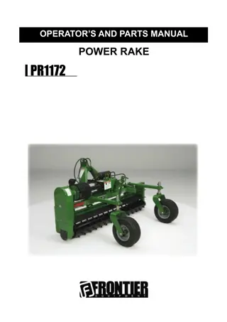
John Deere PR1184 Power Rakes Operator’s and Parts Manual Instant Download (Publication No. 5SPP999800)
Please open the website below to get the complete manualnn// n
Download Presentation

Please find below an Image/Link to download the presentation.
The content on the website is provided AS IS for your information and personal use only. It may not be sold, licensed, or shared on other websites without obtaining consent from the author. Download presentation by click this link. If you encounter any issues during the download, it is possible that the publisher has removed the file from their server.
E N D
Presentation Transcript
OPERATORS AND PARTS MANUAL OPERATOR S AND PARTS MANUAL POWER RAKES POWER RAKES PR1184 PR1184F S/N 700001 & Above 8 S/N 700001 & Above 8
TABLE OF CONTENTS PREFACE..............................................................................................................................2 SAFETY PRECAUTIONS Safety Statements ....................................................................................................3 General Safety Precautions ..................................................................................3-5 Equipment Safety Precautions ..............................................................................5-7 SAFETY DECALS ..............................................................................................................8-9 SET-UP...........................................................................................................................10-13 OPERATIONAL PROCEDURE ......................................................................................14-21 MAINTENANCE .............................................................................................................22-27 TROUBLESHOOTING ........................................................................................................28 SPECIFICATIONS ......................................................................................29 ......................................................................................30 ASSEMBLY AND PARTS IDENTIFICATION .................................................................32-61 5SPP999800 1
PREFACE GENERAL INFORMATION The purpose of this manual is to assist you in operating and maintaining your attach- ment. Read it carefully. It furnishes information and instructions that will help you achieve years of dependable performance. Some information may be general in nature, due to unknown and varying operating condi- procedures suitable to you particular situation. The illustrations and data used in this manual were current at the time of printing. How- ever, due to possible in line production changes, your machine may vary slightly in detail. We reserve the right to redesign and change the machines as may be necessary without Throughout this manual, references are made to right and left direction. These are determined by standing behind the tractor facing the direction of forward travel. LEA EL INSTRUCTIVO! Si no lee Ingles, pida ayuda a alguien que si lo lea para que le truduzca lasmedidas de sequridad. WARNING! Never let anyone operate this unit without reading the "Safety Precautions" and "Operations" sections of this manual. Always choose hard, level ground to park the unit on and set the brake so the unit cannot roll. BEFORE OPERATION The primary responsibility for safety with this equipment falls to the operator. Make sure the equipment is operated only by trained individuals that have read and understand this manual. If there is any portion of this manual or function you do not understand, contact your local Frontier Dealer. SERVICE When servicing your product, remember to use only manufacturer replacement parts. Substitute parts may not meet the standards required for safe, dependable operation. To facilitate parts ordering, record the model and serial number of your unit in the located on the product. Any questions related to this attachment should be directed to your local Frontier dealer. MODEL:__________________________ DATE: ______________________________ SERIAL NUMBER: ___________________________ (See parts section for location.) 2 5SPP999800
https://www.ebooklibonline.com Hello dear friend! Thank you very much for reading. Enter the link into your browser. The full manual is available for immediate download. https://www.ebooklibonline.com
SAFETY STATEMENTS DANGER This statement is used where serious injury or death will result if the instructions are not followed properly. WARNING This statement is used where serious injury or death could result if the instructions are not followed properly. CAUTION This statement is used where minor injury could result if the instructions are not followed properly. NOTICE This statement is used where equipment or property damage could result if the instructions are not followed properly. This symbol by itself or used with a safety signal word throughout this manual is used to call your attention to instructions involving your personal safety or the safety of others. Failure to follow these instructions can result in injury or death. GENERAL SAFETY PRECAUTIONS WARNING READ MANUAL PRIOR TO INSTALL Improper installation, operation, or maintenance of this equipment could result in serious injury or death. Operators and maintenance personnel should read this manual as well as all manuals related to this equipment and the prime mover thoroughly before beginning installation, operation, or maintenance. FOLLOW ALL SAFETY INSTRUCTIONS IN THIS MANUAL AND THE PRIME MOVERS MANUAL. WARNING READ AND UNDERSTAND ALL SAFETY STATEMENTS Read all safety decals and safety statements in all manuals prior to operat- ing or working on this equipment. Know and obey all OSHA regulations, local laws and other professional guidelines for your operation. Know and follow good work practices when assembling, maintaining, repairing, mounting, removing or operating this equipment. KNOW YOUR EQUIPMENT Know your equipment s capabilities, dimensions and operations before operating. Visually inspect your equipment before you start, and never operate equipment that is not in proper working order with all safety devices intact. Check all hardware to assure it is tight. Make certain that all lock- ing pins, latches, and connection devices are properly installed and secured. certain all safety decals are in place and are legible. Keep decals clean, and replace them if they become worn and hard to read. 5SPP999800 3
WARNING PROTECT AGAINST FLYING DEBRIS Always wear proper safety glasses, goggles or a face shield when driving hazardous material. WARNING LOWER OR SUPPORT RAISED EQUIPMENT Do not work under raised 3 point lift arms without supporting them. Do not use support material made of concrete blocks, logs, buckets, barrels or any other material that could suddenly collapse or shift positions. Make sure support material is solid, not decayed, warped, twisted, or tapered. Lower lift arms to ground level or onto blocks. Lower lift arms and attachments to the ground before leaving the cab or operator s station. WARNING USE CARE WITH HYDRAULIC FLUID PRESSURE death. Hydraulic leaks under pressure may not be visible. Before connect- ing or disconnecting hydraulic hoses, read your prime movers operator s manual for detailed instructions on connecting and disconnecting hydraulic Keep unprotected body parts, such as face, eyes and arms as far away may develop gangrene or other permanent disabilities. familiar with this type of injury, ask him to research immediately to determine proper treatment. Wear safety glasses, protective clothing, and use a sound piece of card board or wood when searching for hydraulic leaks. DO NOT USE YOUR HANDS! SEE ILLUSTRATION. WARNING DO NOT MODIFY MACHINE OR ATTACHMENTS the function, safety, life and performance of the attachment. When making repairs, use only the manufacturer s genuine parts, following authorized in- - cations must be authorized in writing by the manufacturer. 4 5SPP999800
WARNING SAFELY OPERATE EQUIPMENT operator in how to use the controls, know its capabilities, dimensions, and all safety requirements. See your prime movers manual for these instructions. Keep all step plates, grab bars, pedals, and controls free of dirt, grease, debris, and oil. being serviced. Do not allow riders on the attachment or the prime mover. Do not operate the equipment from anywhere other than the correct operators position. attachment in a raised position. Do not alter or remove any safety feature from the prime mover or this attachment. doubt on any safety issue, contact your supervisor or safety coordinator WARNING SAFELY MAINTAIN AND REPAIR EQUIPMENT Do not wear loose clothing, or any accessories that can catch in moving parts. If you have long hair, cover or secure it so that it does not become entangled in the equipment. Work on a level surface in a well lit area. Use properly grounded electrical outlets and tools. Use the correct tool for the job at hand. Make sure they are in good condition for the task required. EQUIPMENT SAFETY PRECAUTIONS WARNING Safety is a primary concern in the design and manufacture of our products. Unfortunately, our efforts to provide safe equipment can be wiped out by a of equipment, hazard control and accident prevention are dependent upon the awareness, concern, prudence and proper training of personnel involved in the operation, transport, maintenance and storage of equipment. The designed and tested safety of this equipment depends on it being operated WARNING INITIAL SET-UP AND SYSTEMS CHECK Always check with your prime mover manual or dealer for counter weight ballast that may be required for machine stability. Air in hydraulic systems can cause erratic operation and allows loads or 5SPP999800 5
Before operating equipment purge any air in the system by engaging all hydraulic functions. Check that all control lever positions function as instructed in the Operator s Manual. Do not operate until control lever and equipment movements are correct. and not leaking before starting power unit. Check and route hoses care fully to prevent damage. Hoses must not be twisted, bent sharply, kinked, frayed, pinched, or come into contact with any moving parts. Operate moveable components through full operational range to check clearances. Replace damaged hoses immediately. Ensure implement is properly attached, adjusted and in good condition. Tractor must be equipped with ROPS and seat belt/operator restraint. Keep seat belt/operator restraint securely fastened/engaged. Falling off tractor can result in death from being run over or crushed. Keep ROPS systems in place at all times. WARNING SAFELY OPERATE EQUIPMENT Improper operation can cause the machine to tip or roll over and cause injury or death. Keep tractor lift arms and attachment as low as possible. Turn on level ground. Go up and down slopes, not across them. Keep the heavy end of the machine uphill. Only engage power when equipment is at ground level. Always disengage power when equipment is raised off the ground. Do not disconnect hydraulic lines until all system pressure is relieved. Hydraulic system leak down, hydraulic system failures, mechanical failures or movement of control levers can cause equipment to drop or Always comply with all state and local lighting and marking requirements. Ensure equipment is properly attached, adjusted and in good operating condition. Before starting tractor, check all equipment driveline guards for damage and make sure they rotate freely on all drivelines. Replace any dam- aged guards. If guards do not rotate freely on drivelines, repair and replace bearings before operating. Make sure driveline is correct length to prevent bottoming out or pulling apart during the full lift range of the hitch. Make sure spring-activated locking pin or collar slides freely and is 6 5SPP999800
A minimum 20% of tractor and equipment weight must be on tractor front wheels with attachments in transport position. Without this weight, tractor could tip over causing personal injury or death. The weight may be attained with a loader, front wheel weights, ballast in tires, or front tractor equipment. Do not estimate. Ensure shields and guards are properly installed and in good condition. Replace if damaged. WARNING WATCH FOR OPERATING HAZARDS Look down and to the rear and make sure area is clear before operating in reverse. Watch for hidden hazards on the terrain during operation. obstructions, or on hillsides. Reduce ground speed on slopes and rough terrain. Do not operate on steep slopes. Do not stop, start or change directions suddenly on slopes. Stop tractor and implement immediately upon striking an obstruction. Dis mount tractor using proper procedure. Inspect and repair any damage before resuming operation. WARNING MAINTENANCE SAFETY Your dealer can supply original equipment hydraulic accessories and repair parts. Substitute parts may not meet original equipment the special handling requirements. Disconnect battery before working on electrical system. Remove ground Tighten all bolts, nuts and screws, and check that all cotter pins are installed securely to ensure equipment is in a safe condition before operating. 5SPP999800 7
SAFETY DECALS 5SPP976400 5SPP970300 5SPP976401 5SPP970250 5SPP970300 5SPP970301 5SPP976500 5SPP970400 5SPP970400 5SPP976402 5SPP970100 5SPP970300 8 5SPP999800
SAFETY DECALS 5SPP970250 5SPP970400 5SPP970301 5SPP970300 5SPP976402 5SPP970100 5SPP976401 5SPP976400 5SPP976500 5SPP999800 9
SET-UP SET-UP INSTRUCTIONS The power rake is shipped partially assembled. Assembly will be easier if components are aligned and loosely assembled before tightening hardware. Recommended torque values for hardware are located on page 30. For reference, front, back, left and right directions are determined by sitting in the tractors operator s seat. It is advisable to have a mechanical lifting device to facilitate uncrating. UNPACKING CRATE Be careful of nails in boards when uncrating. 1. Remove top, sides, and ends of crate. 2. Remove mast frame. 3. Remove gauge wheel assemblies. 4. Remove right and left endplates. 5. Remove rake assembly from crate. 6. Remove loose nails from boards and dispose of crate according to local codes. STANDARD MODEL ASSEMBLY PROCEDURE (See Pages 12 & 34) Tools Required 15/16 , 1-7/16 , 1-1/2 combination wrenches 1. Stand rake frame upright and position one endplate on each side of frame to stabilize the rake. 2. Attach the two gauge wheel assemblies to main frame using two 5/8 u-bolts and locking nuts. 3. Slide mast frame between yoke plate on frame, making sure pivot bushing is in place. 4. Install 1 X 6-1/2 bolt with washer on head end (bolt installed from under side of mast). groove. Install supplied 5/8 X 3 GR8 bolts and lock nuts and then tighten. 7. Attach angle cylinder to mast frame. 10 5SPP999800
SET-UP FLEX MODEL ASSEMBLY PROCEDURE (See Pages 12 & 36) Tools Required 15/16 , 1-1/16 , 1-7/16 , 1-1/2 combination wrenches 1. Stand rake frame upright and position one endplate on each side of frame to stabilize the rake. 2. Attach the two gauge wheel assemblies to main frame using two 5/8 U-bolts and locking nuts. 3. Slide mast frame between yoke plate on frame, making sure pivot bushing is in place. 4. Install 1 X 6-1/2 bolt with washer on head end (bolt installed from under side of mast). groove. Install supplied 5/8 X 3 GR8 bolts and lock nuts and then tighten. 7. Attach angle cylinder to mast frame. lock nuts. Do not over tighten. 5SPP999800 11
SET-UP 12 5SPP999800
SET-UP ITEM QTY 1 2 3 4 5 1 1 1 1 1 5SPM27128 5SPM27129 5SPP403500 5SPM18044 5SPM27106 Right Endplate W/Pin Left Endplate W/Pin Main PTO Pivot Bolt 3 Lock Pin 6 7 8 9 1 1 1 1 5SPM27107 5SPM6581 5SPM27103 5SPP850116 Drive Shield Shield Clamp 1 X 6-1/2 Pivot Bolt 1 Zinc Flat Washer 11 1 5SPP115406 1/4 -20 X 1-1/2 Fillister Head Screw 13 1 5MP1503 3/8 Lock Washer 5SPP999800 13
OPERATIONAL PROCEDURE NOTICE and for thatching. This manual contains information for all tractor mounted ATTACHING POWER RAKE TO TRACTOR Move tractor into position in front of the power rake. Move back slowly and carefully, not allowing anyone to be between the tractor and the rake. Turn off tractor engine. Attach the two lower arms of the 3-point hitch with the two hitch-pin assemblies. Attach the tractor center link to the upper hitch point of the power rake. Use either the lock-out Attach the front PTO from the power rake to the tractor. Slide the front section of the PTO into the back section and attach to the PTO shaft at the rear of the tractor. Reattach driveline storage chain in its original position so that it will not contact PTO driveline. If the PTO is too long, servere PTO and gearbox damage is possible when hooking up the PTO from the power rake to the tractor. The front PTO is long enough to fit a variety of tractors. It is possible that the front PTO may be to long for you application. If this is the case, see you dealer for replace- ment driveline or for factory approved modification to existing driveline. Attach the two hydraulic lines on the rake to the two female hydraulic couplers on the tractor. The hydraulic hose ends on the power rake are ISO male couplers, which are compatible with newer tractors. Raise jack stand and secure in operating position. coming from the switch. Be careful when routing the cable that sharp edges or moving parts will not damage the cable. Always clean connector ends prior to attaching. Dirt could POWER RAKE FUNCTION The tractor PTO drives the roller, which digs into the ground, cultivating and pulling up rocks, roots, and debris. 14 5SPP999800
OPERATIONAL PROCEDURE The clean soil goes between the roller and barrier, while the rocks, roots, and debris work to the side in a windrow. With the endplates mounted in the working position and the rake straight (endplates parallel start-up. Failure to run the clutch in could result in pre-mature driveline failure and warranty will be voided. Start tractor engine. Lower power rake slowly to the ground. Engage tractor PTO. Move the tractor forward. Select a slow tractor speed and increase slightly until operation is satisfactory. NOTICE Disengage the PTO any time that the roller is raised out of the ground. Ground Speed Ground speed should be between 3 and 5 MPH under normal conditions. In heavy rock, reduce the ground speed to 1 to 3 MPH. Power Rake Angle Adjustment The power rake may be angled up to 15 degrees left or right for placing material in a windrow. For standard models, with the power rake angle cylinder connected to a tractor hydraulic control valve, move tractor control valve to select the desired angle. Return the tractor control to neutral to maintain the selected angle. to angle right or left. Power Roller The roller should be level with the ground. To level rake from side to side, adjust one of the tractor 3-point lower lift arms. 5SPP999800 15
Suggest: If the above button click is invalid. Please download this document first, and then click the above link to download the complete manual. Thank you so much for reading
OPERATIONAL PROCEDURE The power rake should be level front to back. Level the rake using the tractor 3-point top link, the 3-point lift arms, or the gauge wheels. On standard models, to allow the roller to penetrate deeper into the ground, loosen the handle achieve the opposite, lower the gauge wheels. Be sure to check the air pressure in each tire regularly so that an even, consistent grade will be maintained. Barrier (Barrier adjustment location is shown on page 20.) The normal gap between the roller and barrier for average conditions is about 1-1/4 . This gap can be adjusted by rotating the barrier and pinning in desired position. A wider opening raking, reduce the gap. (Be careful not to let roller hit barrier). The gap should be the same all the way across. OPERATING DEPTH When power raking, the depth will determine how much dirt is carried ahead of the roller. The ideal depth will vary with conditions and can be anywhere from skimming the surface to about 3 inches deep. See instructions in Power Roller above to set roller depth. the windrow two or three times, the level of the dirt may be to the top of the barrier. However, The power rake allows fast raking of large areas of ground by being able to move windrows several times. Of course, the volume or density of the material being raked will dictate how many times a windrow can be moved. Soil can be removed from the windrow of rocks by moving it back and forth a few times onto the clean area. If dirt clods are a problem, running the tractor tire over the windrow and then Endplates The function of the endplates is to contain the material in front of the roller while the clean material passes between the roller and barrier. With the endplates mounted in the operating position and the rake straight (endplates parallel By decreasing the gap between the roller and barrier, more material can be pulled along. When not using the endplates for operation, they can be placed in storage position, see page 30. Make sure the disconnected power rake is stored on a hard, level surface. Use the endplates 16 5SPP999800
https://www.ebooklibonline.com Hello dear friend! Thank you very much for reading. Enter the link into your browser. The full manual is available for immediate download. https://www.ebooklibonline.com


