John Deere 6400 Tractors Service Repair Manual Instant Download (TM4523)
Please open the website below to get the complete manualnn//
Download Presentation

Please find below an Image/Link to download the presentation.
The content on the website is provided AS IS for your information and personal use only. It may not be sold, licensed, or shared on other websites without obtaining consent from the author. Download presentation by click this link. If you encounter any issues during the download, it is possible that the publisher has removed the file from their server.
E N D
Presentation Transcript
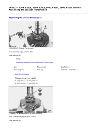
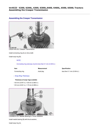
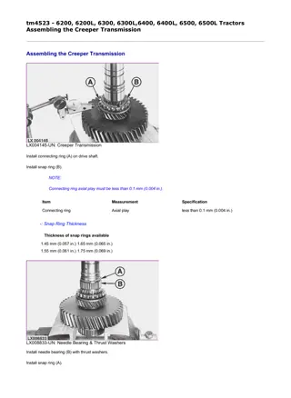
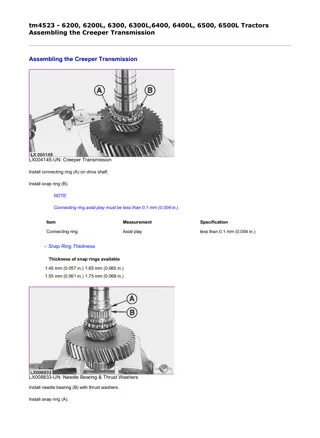
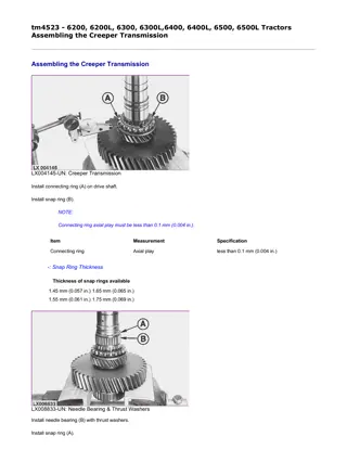
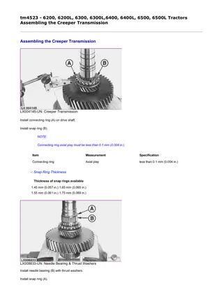
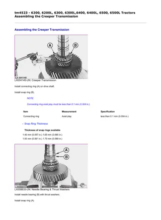
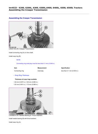
1/5 tm4523 - 6200, 6200L, 6300, 6300L,6400, 6400L, 6500, 6500L Tractors Assembling the Creeper Transmission Assembling the Creeper Transmission LX004145-UN: Creeper Transmission Install connecting ring (A) on drive shaft. Install snap ring (B). NOTE: Connecting ring axial play must be less than 0.1 mm (0.004 in.). Item Measurement Specification Connecting ring Axial play less than 0.1 mm (0.004 in.) -: Snap Ring Thickness Thickness of snap rings available 1.45 mm (0.057 in.) 1.65 mm (0.065 in.) 1.55 mm (0.061 in.) 1.75 mm (0.069 in.) LX008833-UN: Needle Bearing & Thrust Washers Install needle bearing (B) with thrust washers. Install snap ring (A). file:///C:/ProgramData/Service%20ADVISOR/Temp/tm4523_LXOUOE00319... 2020/6/30
2/5 LX000220-UN: Gears Position gear (B) on gear (C). Install thrust washer (A) and snap ring. Older tractor series: LX000221-UN: Shift Collar LX000222-UN: Install Shift Collar W/Pins Install shift collar (A). Before installing shift collar, mark position of bores and splines (see arrows). Grease pins and install on shift collar. Install shift collar with pins. Latest tractor series: file:///C:/ProgramData/Service%20ADVISOR/Temp/tm4523_LXOUOE00319... 2020/6/30
3/5 LX1016947-UN: Retaining Ring LX1016948-UN: Pin Installation Install retaining ring (A) on the shift collar. Install pins (B). Install the shift collar and pins. LX008834-UN: Drive Shaft Gears Install gears on drive shaft. NOTE: file:///C:/ProgramData/Service%20ADVISOR/Temp/tm4523_LXOUOE00319... 2020/6/30
https://www.ebooklibonline.com Hello dear friend! Thank you very much for reading. Enter the link into your browser. The full manual is available for immediate download. https://www.ebooklibonline.com
4/5 When installing gears, press shift collar against gears. This prevents the shift collar and pins from falling out. LX008835-UN: Snap Ring Installation Install the two axial bearings. Install snap ring (A). Install lower snap ring of needle bearing. LX008836-UN: Needle Bearing With Thrust Washers Install needle bearing (B) with thrust washers. Install upper snap ring (A). LX008831-UN: Drive Shaft & Double Gear Ball Bearings Install ball bearing (B) of drive shaft and ball bearing (A) of double gear. file:///C:/ProgramData/Service%20ADVISOR/Temp/tm4523_LXOUOE00319... 2020/6/30
5/5 LX008830-UN: Drive Shaft & Double Gear Install drive shaft (B) and double gear (A). LX008963-UN: Snap Rings Install snap rings (A) and (B). LX,5020009567N-19-1997/06/01 file:///C:/ProgramData/Service%20ADVISOR/Temp/tm4523_LXOUOE00319... 2020/6/30
1/2 tm4523 - 6200, 6200L, 6300, 6300L,6400, 6400L, 6500, 6500L Tractors Sectional View of Shift Linkage Sectional View of Shift Linkage LX008837-UN: Shift Linkage-Sectional View LEGEND: A - Shaft B - Shifter shaft C - Shifter fork D - Locking pin E - Shifter shaft ranges C and D Installation instructions NOTE: file:///C:/ProgramData/Service%20ADVISOR/Temp/tm4523_LXOUOE00319... 2020/6/30
2/2 Shifter shaft (E) is a component of the range transmission and protrudes into the creeper transmission once the latter is installed. If necessary, install locking pin (D). Locking pin (D) must be raised when the creeper transmission is installed so that the housing can be pushed over shifter shaft (F). LX,5020006853-19-1997/06/01 file:///C:/ProgramData/Service%20ADVISOR/Temp/tm4523_LXOUOE00319... 2020/6/30
1/1 tm4523 - 6200, 6200L, 6300, 6300L,6400, 6400L, 6500, 6500L Tractors Installing the Shift Linkage Installing the Shift Linkage LX008829-UN: Shift Linkage-Installation Install shifter shaft (B) with shifter fork (C). Install shaft (A). LX008838-UN: Threaded Pins Tighten threaded pins to 40 N m (30 lb-ft). Item Measurement Specification Threaded Pins of Shifter Fork Torque 40 N m (30 lb-ft) LX,5020006854-19-1997/06/01 file:///C:/ProgramData/Service%20ADVISOR/Temp/tm4523_LXOUOE00319... 2020/6/30
1/2 tm4523 - 6200, 6200L, 6300, 6300L,6400, 6400L, 6500, 6500L Tractors Repairing the Shift Cover Repairing the Shift Cover LX014431-UN: Repairing the Shift Cover LEGEND: A - Shaft B - O-ring C - Cap screw D - Shift cover E - Cap screw (7 used) F - Lever G - Spring pin (dia. 5 mm; 13/64 in.) H - Spring pin (dia. 8 mm; 5/16 in.) I - Dowel pin J - Gasket NOTE: Use an M6 screw to extract dowel pin (I). file:///C:/ProgramData/Service%20ADVISOR/Temp/tm4523_LXOUOE00319... 2020/6/30
2/2 Drive spring pins (G) into spring pins (H). They must be offset by 180 degrees. NOTE: Up to transm. serial no. 115624, lever (F) has only one 6 mm (15/64 in.) dia. spring pin. If necessary, replace this spring pin with spring pins (G) and (H). This also requires the replacement of shifter shaft (A) and lever (F). LX,RDTH002000-19-1996/04/01 file:///C:/ProgramData/Service%20ADVISOR/Temp/tm4523_LXOUOE00319... 2020/6/30
1/3 tm4523 - 6200, 6200L, 6300, 6300L,6400, 6400L, 6500, 6500L Tractors Final Assembly Final Assembly LX000228-UN: Needle Bearing Install needle bearing (A) of double gear into the range transmission. NOTE: When installing the creeper transmission, raise the long locking pin ( see Sectional View of Shift Linkage ) so that the housing can be pushed over the shifter shaft that protrudes out of the range transmission. LX002331-UN: Transmission Housing Install the transmission housing. See Group 00 . SyncroPlus transmission: Install the gear transmission and PERMA-CLUTCH 2 . See Group 00 . PowrQuad transmission: Install the PowrQuad module. See Section 55, Group 00 . file:///C:/ProgramData/Service%20ADVISOR/Temp/tm4523_LXOUOE00319... 2020/6/30
2/3 LX008839-UN: Shifter Shaft Lock LEGEND: A - Ball B - Spring Install shifter shaft lock. LX008840-UN: Shift Cover Install shift cover. Tighten cap screws to 30 N m (22 lb-ft). Item Measurement Specification file:///C:/ProgramData/Service%20ADVISOR/Temp/tm4523_LXOUOE00319... 2020/6/30
3/3 Shift Cover to Transmission Housing, Cap Screws Torque 30 N m (22 lb-ft) PERMA-CLUTCH 2 is a trademark of Deere & Company. PowrQuad is a trademark of Deere & Company. LX,RDTH002001-19-1996/04/01 file:///C:/ProgramData/Service%20ADVISOR/Temp/tm4523_LXOUOE00319... 2020/6/30
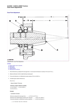
1/1 tm4523 - 6200, 6200L, 6300, 6300L,6400, 6400L, 6500, 6500L Tractors Specifications Specifications Item Measurement Specification Main shaft Axial play less than 0.1 mm (0.004 in.) Main shaft and ring gear Cone point distance 0.06 mm (0.0024 in.) Front wheel drive gear Axial play less than 0.1 mm (0.004 in.) Range gears Axial play 0.15 to 0.60 mm (0.006 to 0.024 in.) Synchronizer units Axial play less than 0.1 mm (0.004 in.) Drive shaft Axial play less than 0.1 mm (0.004 in.) Drive shaft bearing quill to differential housing, attaching screws and bolts Torque 55 N m (40 lb-ft) Main shaft bearing quill to differential housing, cap screws Torque 55 N m (40 lb-ft) Parking lock shifter shaft Clearance 0.25 to 0.60 mm (0.010 to 0.024 in.) Transmission housing to differential housing, cap screws Grade 8.8 Torque 90 N m (65 lb-ft) 120 N m (90 lb-ft) Grade 10.9 Torque 120 N m (90 lb-ft) Needle bearings in transmission housing, cap screws Torque 30 N m (22 lb-ft) Threaded pins of shifter forks Torque 40 N m (30 lb-ft) Shift cover to transmission housing, cap screws Torque 30 N m (22 lb-ft) Countersunk screw in differential drive shaft Torque 25 N m (18 lb-ft) -: Adjusting Cone Point pf Diff. Drive Shaft Adjusting Cone Point pf Diff. Drive Shaft (Determining Spacer Washer Thickness): Example (a) Dimension stamped on bevel gear face, read.............. 172.0 mm (6.772 in.) (b) Dimension from needle bearing to bearing quill, measured.............. + 48.1 mm (1.894 in.) (c) Cone point dimension of differential housing as specified.............. -219.5 mm (8.642 in.) (d) Required shim thickness.............. = 0.6 mm (0.014 in.) NOTE: In most cases the dimension (a) stamped on bevel gear face is exactly 172,0 mm (6.772 in.). LX,RDTG000823N-19-1997/06/01 file:///C:/ProgramData/Service%20ADVISOR/Temp/tm4523_LXOUOE00319... 2020/6/30
1/2 tm4523 - 6200, 6200L, 6300, 6300L,6400, 6400L, 6500, 6500L Tractors General Repair Procedures- Range Transmission General Repair Procedures- Range Transmission NOTE: Before beginning the repair, review the following guidelines. These are provided to emphasize the need for attention to detail and care when servicing the range transmission. Thoroughly clean the outside of the housing before commencing disassembly. Handle parts carefully to prevent nicking or burring machined surfaces. The repair area should be kept clean, well organized, and supplied with clean lint-free shop cloths. Inspect before Disassembly Inspect the range transmission shafts and countershafts before removal. Inspection may make it easier to decide what repairs are required. Wipe lubricant off the internal components and examine them to determine if there is excessive wear or damage. Disassembly and Assembly Many parts and surfaces are precision machined. Careful handling during disassembly, cleaning, inspection and assembly can prevent unnecessary damage. Lubricate each component part with clean hydraulic oil. Needle bearings and thrust washers should be lightly coated with petroleum jelly during assembly. Use new O-rings, seals and gaskets. Comply with the prescribed specifications (torques, settings). Cleaning and Inspection Clean all parts with clean suitable solvent and use moisture-free air to dry parts. Bearings Never dry bearings with compressed air. Spinning a bearing without lubrication can damage the bearing. Clean the bearings with clean solvent, dry thoroughly, and oil before inspection. Inspect bearings for signs of wear or damage. Inspect thrust washers and thrust surfaces for signs of wear or damage. Springs Inspect all springs for wear, damage or distortion. Shafts Inspect the shaft bearing surfaces for wear or damage. If excessive wear or damage is detected, replace the shaft and bearings. Inspect the shafts for wear or damage. Gears Inspect the gear teeth for signs of wear or damage. file:///C:/ProgramData/Service%20ADVISOR/Temp/tm4523_LXOUOE00319... 2020/6/30
2/2 LX000775-UN: Range Transmission LEGEND: A - Countershaft of gear transmission B - Drive shaft C - Gear of range D D - Synchronizer unit E - Gear of range C F - Gear of range B G - Gear of range A H - Front wheel drive gear I - Differential drive shaft LX,5025007066-19-1994/06/01 file:///C:/ProgramData/Service%20ADVISOR/Temp/tm4523_LXOUOE00319... 2020/6/30
1/1 tm4523 - 6200, 6200L, 6300, 6300L,6400, 6400L, 6500, 6500L Tractors Preliminary Work Preliminary Work LX009119-UN: Preliminary Work 1. Remove shift cover (A). 2. SyncroPlus transmission: Remove hydraulic clutch and gear transmission, see Group 00 . PowrQuad transmission: Remove PowrQuad module , see Group 00 . 3. If equipped, remove creeper transmission, see Group 00 . 4. Remove front wheel drive clutch, see Section 56, Group 10. 5. Remove PTO [ Only necessary when differential drive shaft is to be removed.] , see Section 56, Group 00 . 6. Remove final drives [ Only necessary when differential drive shaft is to be removed.] , see Section 56, Group 00 . 7. Remove differential [ Only necessary when differential drive shaft is to be removed.] , see Section 56, Group 15 . PowrQuad is a trademark of Deere & Company. LX,5025007010-19-1994/06/01 file:///C:/ProgramData/Service%20ADVISOR/Temp/tm4523_LXOUOE00319... 2020/6/30
1/2 tm4523 - 6200, 6200L, 6300, 6300L,6400, 6400L, 6500, 6500L Tractors Disassembling Range Transmission Disassembling Range Transmission LX009120-UN: Disassembling Range Transmission Remove cap screws (A). Remove transmission housing. LX009121-UN: Spring & Drive Shaft Disconnect spring (A) and remove drive shaft (B). file:///C:/ProgramData/Service%20ADVISOR/Temp/tm4523_LXOUOE00319... 2020/6/30
2/2 LX009122-UN: Shift Shafts & Forks LEGEND: A - Shifter shaft (ranges A and B) B - Shifter fork (ranges A and B) C - Shifter fork (ranges C and D) D - Shifter shaft (ranges C and D) Remove shifter shafts and shifter forks. LX000782-UN: Diff. Drive Shaft Cap Screws Turn out cap screws (A) and remove differential drive shaft. LX,RDTG002105-19-1994/06/01 file:///C:/ProgramData/Service%20ADVISOR/Temp/tm4523_LXOUOE00319... 2020/6/30
1/1 tm4523 - 6200, 6200L, 6300, 6300L,6400, 6400L, 6500, 6500L Tractors Exploded View of Differential Drive Shaft Exploded View of Differential Drive Shaft LX1016986-UN: Differential Drive Shaft LEGEND: A - Cap screw (5 used) B - Bracket C - Differential drive shaft D - Needle bearing assy. E - Axial bearing assy. F - Shim (use as required) G - Bearing quill H - Spring (5 used) I - Snap ring (thickness as required) J - Spacer [Earlier tractor series] K - Snap ring L - Front wheel drive gear M - Thrust washer (thickness as required) N - Gear of range A O - Synchronizer assy. P - Snap ring (thickness as required) Q - Gear of range B R - Washer (up to transm. serial no. 157465) S - Snap ring (2.0 m; 0.079 in. thick; up to transm. serial no. 57465) T - Snap ring (3.0 m; 0.118 n. thick; from transm. serial no. 57466) U - Gear of range C V - Gear of range D W - Countersunk screw X - Needle bearing Y - Cap screw (1 [Later tractor series] [ Earlier tractor series] used) LX,RDTG002110N-19-1997/06/01 file:///C:/ProgramData/Service%20ADVISOR/Temp/tm4523_LXOUOE00319... 2020/6/30
1/1 tm4523 - 6200, 6200L, 6300, 6300L,6400, 6400L, 6500, 6500L Tractors Exploded View of Drive Shaft and Parking Lock Exploded View of Drive Shaft and Parking Lock LX009194-UN: Drive Shaft & Parking Lock LEGEND: A - Bearing quill B - Pin C - Spring D - Taper roller bearing cup E - Taper roller bearing cone F - Drive shaft G - Sealing sleeve (older tractors only) H - Taper roller bearing cone I - Taper roller bearing cup J - Snap ring K - Shaft L - Hex. socket screw M - Pin N - Locking latch O - Roller P - Shifter cam Q - Axial bearing assy. R - Spacer washer (thickness as required) S - Bushing T - Seal ring U - Spring V - Lever LX,RDTG002111-19-1997/06/01 file:///C:/ProgramData/Service%20ADVISOR/Temp/tm4523_LXOUOE00319... 2020/6/30
1/1 tm4523 - 6200, 6200L, 6300, 6300L,6400, 6400L, 6500, 6500L Tractors Exploded View of Shift Mechanism Exploded View of Shift Mechanism LX1017514-UN: Shift Mechanism LEGEND: A - Forward/reverse linkage assembly [ PowrQuad transmission] B - Fwd/rev. shifter shaft [ PowrQuad transmission] C - Lever [PowrQuad transmission ] [Up to transmission serial no. 156441] D - Cover [SyncroPlus or PowrQuad transm. with el. reverser control on steering column] E - Shifter shaft F - Ball bushing (4 used) G - Locking pin (2 used) H - Shifter shaft housing I - Shifter shaft J - Shift fork K - Plastic tips (4 used) (latest tractor series) L - Spring [If equipped ] M - Lever [If equipped ] N - Roller [If equipped ] O - Lever [If equipped ] P - Cam [PowrQuad transmission ] [Up to transmission serial no. 173498] Q - Dowel pin [If equipped ] R - Fwd/rev. shifter shaft [ PowrQuad transmission] [ Up to transmission serial no. 156441] S - Lever [PowrQuad transmission ] [Up to transmission serial no. 156441] T - Lever [PowrQuad transmission ] U - Lever [PowrQuad transmission ] V - Pin [PowrQuad transmission ] [Up to transmission serial no. 173498] W - Pin [PowrQuad transmission ] [Up to transmission serial no. 173498] LX,RDTG002112N-19-1997/06/01 file:///C:/ProgramData/Service%20ADVISOR/Temp/tm4523_LXOUOE00319... 2020/6/30
MORE MANUALS: https://www.ebooklibonline.com/ Suggest: If the above button click is invalid. Please download this document first, and then click the above link to download the complete manual. Thank you so much for reading
1/2 tm4523 - 6200, 6200L, 6300, 6300L,6400, 6400L, 6500, 6500L Tractors Exploded View of Shift Cover Exploded View of Shift Cover LX1017515-UN: Shift Cover LEGEND: A - Shifter shaft (2 used) B - Pin C - Cover D - Seal E - Seal F - Lever (2 St.)) G - 8 mm (5/16 in.) dia. spring pin (2 used) H - 5 mm (13/64 in.) dia. spring pin (2 used) I - Dowel Pin (2 used) J - Shift Cover K - Stop Assembly (prevents sticking; if equipped) Repairing the shaft cover NOTE: Use an M6 screw to extract dowel pins (I). file:///C:/ProgramData/Service%20ADVISOR/Temp/tm4523_LXOUOE00319... 2020/6/30
https://www.ebooklibonline.com Hello dear friend! Thank you very much for reading. Enter the link into your browser. The full manual is available for immediate download. https://www.ebooklibonline.com


