John Deere 314F, 518R, and 820R Walk-Behind Tillers Service Repair Manual Instant Download (TM1687)
Please open the website below to get the complete manualnn//

Download Presentation

Please find below an Image/Link to download the presentation.
The content on the website is provided AS IS for your information and personal use only. It may not be sold, licensed, or shared on other websites without obtaining consent from the author. Download presentation by click this link. If you encounter any issues during the download, it is possible that the publisher has removed the file from their server.
E N D
Presentation Transcript
314F, 518R, and 820R Walk-Behind Tillers TECHNICAL MANUAL John Deere Worldwide Commercial and Consumer Equipment Division TM1687 (01Jan97) Litho in U.S.A
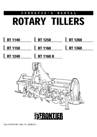
Walk-Behind Tillers Model 314F Model 518R Model 820R
INTRODUCTION This technical manual is written for an experienced technician and contains sections that are specifically for this product. It is a part of a total product support program. Safety Specifications and Information The manual is organized so that all the information on a particular system is kept together. The order of grouping is as follows: Engine Table of Contents General Diagnostic Information Specifications Electrical Wiring Harness Legend Component Location System Schematic Wiring Harness Troubleshooting Chart Theory of Operation Diagnostics Tests & Adjustments Repair Electrical Power Train Note: Depending on the particular section or system being covered, not all of the above groups may be used. Each section will be identified with a symbol rather than a number. The pages within a section will be consecutively numbered. Headings in each section indicate the job being performed. A heading with no model designation applies to all the models in this manual. Headings followed by model designations apply only to those models. All information, illustrations and specifications in this manual are based on the latest information available at the time of publication. The right is reserved to make changes at any time without notice. We appreciate your input on this manual. To help, there are postage paid post cards included at the back. If you find any errors or want to comment on the layout of the manual please fill out one of the cards and mail it back to us. Miscellaneous COPYRIGHT 1997 John Deere Worldwide Commercial and Consumer Equipment Division Horicon, WI All rights reserved 1 - 1 1/7/97
https://www.ebooklibonline.com Hello dear friend! Thank you very much for reading. Enter the link into your browser. The full manual is available for immediate download. https://www.ebooklibonline.com
SAFETY RECOGNIZE SAFETY INFORMATION HANDLE FLUIDS SAFELY-AVOID FIRES BE PREPARED FOR EMERGENCIES This is the safety-alert symbol. When you see this symbol on your machine or in this manual, be alert to the potential for personal injury. Follow recommended precautions and safe servicing practices. UNDERSTAND SIGNAL WORDS A signal word DANGER, WARNING, or CAUTION is used with the safety-alert symbol. DANGER identifies the most serious hazards. Danger or Warning safety signs are located near specific hazards. CAUTION safety signs are used where general precautions should be used. CAUTION also calls attention to safety messages in this manual. When you work around fuel, do not smoke or work near heaters or other fire hazards. Store flammable fluids away from fire hazards. Do not incinerate or puncture pressurized containers. Make sure machine is clean of trash, grease, and debris. Do not store oily rags; they can ignite and burn spontaneously. Be prepared if a fire starts. Keep a first aid kit and fire extinguisher handy. Keep emergency numbers for doctors, ambulance service, hospital, and fire department near your telephone. REPLACE SAFETY SIGNS Replace missing or damaged safety signs. See the machine operator s manual for correct safety sign placement. 1 - 2 1/16/97
SAFETY USE SAFE SERVICE PROCEDURES PARK MACHINE SAFELY WEAR PROTECTIVE CLOTHING Before working on the machine: 1. Be sure all equipment is resting firmly on the ground. 2. Stop the engine. 3. Disconnect the spark plug. 4. Hang a DO NOT OPERATE tag in operator station. SUPPORT MACHINE PROPERLY AND USE PROPER LIFTING EQUIPMENT Wear close fitting clothing and safety equipment appropriate to the job. Prolonged exposure to loud noise can cause impairment or loss of hearing. Wear a suitable hearing protective device such as earmuffs or earplugs to protect against objectionable or uncomfortable loud noises. Operating equipment safely requires the full attention of the operator. Do not wear radio or music headphones while operating machine. SERVICE MACHINES SAFELY If you must work on a lifted machine or attachment, securely support the machine or attachment. Do not support the machine on cinder blocks, hollow tiles, or props that may crumble under continuous load. Do not work under a machine that is supported solely by a jack. Follow recommended procedures in this manual. Lifting heavy components incorrectly can cause severe injury or machine damage. Follow recommended procedure for removal and installation of components in the manual. Tie long hair behind your head. Do not wear a necktie, scarf, loose clothing, or necklace when you work near machine tools or moving parts. If these items were to get caught, severe injury could result. Remove rings and other jewelry to prevent electrical shorts and entanglement in moving parts. WORK IN A CLEAN AREA Before starting a job: 1. Clean work area and machine. 2. Make sure you have all necessary tools to do your job. 3. Have the right parts on hand. 4. Read all instructions thoroughly; do not attempt shortcuts. USE PROPER TOOLS Use tools appropriate to the work. Makeshift tools and procedures can create safety hazards. Use power tools only to loosen threaded parts and fasteners. For loosening and tightening hardware, use the correct size tools. DO NOT use U.S. measurement tools on metric fasteners. Avoid bodily injury caused by slipping wrenches. Use only service parts meeting John Deere specifications. USING HIGH PRESSURE WASHERS Directing pressurized water at electronic/electrical components or connectors, bearings, hydraulic seals, fuel injection pumps or other sensitive parts and components may cause product malfunctions. Reduce pressure and spray at a 45 to 90 degree angle. 1 - 3 1/16/97
SAFETY Illuminate Work Area Safely Illuminate your work area adequately but safely. Use a portable safety light for working inside or under the machine. Make sure the bulb is enclosed by a wire cage. The hot filament of an accidentally broken bulb can ignite spilled fuel or oil. Avoid Harmful Asbestos Dust Avoid breathing dust that may be generated when handling components containing asbestos fibers. Inhaled asbestos fibers may cause lung cancer. Components in products that may contain asbestos fibers are brake pads, brake band and lining assemblies, clutch plates, and some gaskets. The asbestos used in these components is usually found in a resin or sealed in some way. Normal handling is not hazardous as long as airborne dust containing asbestos is not generated. Avoid creating dust. Never use compressed air for cleaning. Avoid brushing containing asbestos. When servicing, wear an approved respirator. A special vacuum cleaner is recommended to clean asbestos. If not available, apply a mist of oil or water on the material containing asbestos. Keep bystanders away from the area. Work In Ventilated Area or grinding material Engine exhaust fumes can cause sickness or death. If it is necessary to run an engine in an enclosed area, remove the exhaust fumes from the area with an exhaust pipe extension. If you do not have an exhaust pipe extension, open the doors and get outside air into the area. SERVICE TIRES SAFELY WARNING: California Proposition 65 Gasoline engine exhaust from this product contains chemicals known to the State of California to cause cancer, birth defects, or other reproductive harm. Remove Paint Before Welding Or Heating Avoid potentially toxic fumes and dust. Hazardous fumes can be generated when paint is heated by welding, soldering, or using a torch. Do all work outside or in a well ventilated area. Dispose of paint and solvent properly. Remove paint before welding or heating: If you sand or grind paint, avoid breathing the dust. Wear an approved respirator. If you use solvent or paint stripper, remove stripper with soap and water before welding. Remove solvent or paint stripper containers and other flammable material from area. Allow fumes to disperse at least 15 minutes before welding or heating. Explosive separation of a tire and rim parts can cause serious injury or death. Do not attempt to mount a tire unless you have the proper equipment and experience to perform the job. Always maintain the correct tire pressure. Do not inflate the tires above the recommended pressure. Never weld or heat a wheel and tire assembly. The heat can cause an increase in air pressure resulting in a tire explosion. Welding can structurally weaken or deform the wheel. When inflating tires, use a clip-on chuck and extension hose long enough to allow you to stand to one side and NOT in front of or over the tire assembly. Use a safety cage if available. Check wheels for low pressure, cuts, bubbles, damaged rims or missing lug bolts and nuts. 1 - 4 1/16/97
SAFETY AVOID INJURY FROM ROTATING TINES LIVE WITH SAFETY Keep hands and feet away while machine is running. Shut off engine before starting service. Do not defeat safey systems to allow machine to operate unattended. Before returning machine to customer, make sure machine is functioning properly, especially the safety systems. Install all guards and shields. HANDLE CHEMICAL PRODUCTS SAFELY Direct exposure to hazardous chemicals can cause serious injury. Potentially hazardous chemicals used with John Deere equipment include such items as lubricants, coolants, paints, and adhesives. A Material Safety Data Sheet (MSDS) provides specific details on chemical products: physical and health hazards, safety procedures, and emergency response techniques. Check the MSDS before you start any job using a hazardous chemical. That way you will know exactly what the risks are and how to do the job safely. Then follow procedures and recommended equipment. Dispose of Waste Properly Improperly disposing of waste can threaten the environment and ecology. Potentially harmful waste used with John Deere equipment include such items as oil, fuel, coolant, brake fluid, filters, and batteries. Use leakproof containers when draining fluids. Do not use food or beverage containers that may mislead someone into drinking from them. Do not pour waste onto the ground, down a drain, or into any water source. Inquire on the proper way to recycle or dispose of waste from your local environmental or recycling center, or from your John Deere dealer. 1 - 5 1/16/97
CONTENTS SPECIFICATIONS & INFORMATION CONTENTS Page SPECIFICATIONS TORQUE VALUES . . . . . . . . . . . . . . . . . . . . . . . . . . . . . . . . . . . . . . . . . . 2 METRIC FASTENER TORQUE VALUES . . . . . . . . . . . . . . . . . . . . . . . . . . . . . . . . . . 2 INCH FASTENER TORQUE VALUES. . . . . . . . . . . . . . . . . . . . . . . . . . . . . . . . . . . . . 3 GASOLINE . . . . . . . . . . . . . . . . . . . . . . . . . . . . . . . . . . . . . . . . . . . . . . . . 4 GASOLINE NORTH AMERICA . . . . . . . . . . . . . . . . . . . . . . . . . . . . . . . . . . . . . . . . 4 GASOLINE STORAGE NORTH AMERICA. . . . . . . . . . . . . . . . . . . . . . . . . . . . . . . 4 GASOLINE EUROPE . . . . . . . . . . . . . . . . . . . . . . . . . . . . . . . . . . . . . . . . . . . . . . . . 5 GASOLINE STORAGE EUROPE. . . . . . . . . . . . . . . . . . . . . . . . . . . . . . . . . . . . . . . 5 LUBRICATION . . . . . . . . . . . . . . . . . . . . . . . . . . . . . . . . . . . . . . . . . . . . . 6 ENGINE OIL NORTH AMERICA . . . . . . . . . . . . . . . . . . . . . . . . . . . . . . . . . . . . . . . 6 ENGINE OIL EUROPE . . . . . . . . . . . . . . . . . . . . . . . . . . . . . . . . . . . . . . . . . . . . . . . 6 ENGINE BREAK IN OIL NORTH AMERICA. . . . . . . . . . . . . . . . . . . . . . . . . . . . . . 7 ENGINE BREAK IN OIL EUROPE . . . . . . . . . . . . . . . . . . . . . . . . . . . . . . . . . . . . . 8 ANTI-CORROSION GREASE. . . . . . . . . . . . . . . . . . . . . . . . . . . . . . . . . . . . . . . . . . . 9 ALTERNATIVE LUBRICANTS. . . . . . . . . . . . . . . . . . . . . . . . . . . . . . . . . . . . . . . . . . . 9 SYNTHETIC LUBRICANTS. . . . . . . . . . . . . . . . . . . . . . . . . . . . . . . . . . . . . . . . . . . . . 9 LUBRICANT STORAGE . . . . . . . . . . . . . . . . . . . . . . . . . . . . . . . . . . . . . . . . . . . . . . . 9 MIXING OF LUBRICANTS . . . . . . . . . . . . . . . . . . . . . . . . . . . . . . . . . . . . . . . . . . . . . 9 GREASE NORTH AMERICA. . . . . . . . . . . . . . . . . . . . . . . . . . . . . . . . . . . . . . . . . 10 GREASE EUROPE . . . . . . . . . . . . . . . . . . . . . . . . . . . . . . . . . . . . . . . . . . . . . . . . 10 GEAR CASE AND TRANSMISSION GREASE NORTH AMERICA. . . . . . . . . . . . 11 GEAR CASE AND TRANSMISSION GREASE EUROPE . . . . . . . . . . . . . . . . . . . 11 PRODUCT IDENTIFICATION LOCATIONS . . . . . . . . . . . . . . . . . . . . . . 12 2 - 1 1/16/97
SPECIFICATIONS ENGINE SPECIFICATIONS ENGINE SPECIFICATIONS 314F Tecumseh H30 Air cooled (4) 518R Briggs & Stratton 135292 Air cooled (4) 820R Briggs & Stratton 196432 Air cooled (4) Manufacturer Model Type (cycle) Horsepower@ RPM 3 hp (2.23 kW)@ 3600 RPM 5 hp (3.72 kW)@ 3250 RPM 8 hp (5.9 kW)@ 3250 RPM Displacement 148.5 cc (9.06 cu. in.) 206 cc (12.57 cu. in.) 319 cc (19.44 cu. in.) Slow Idle Speed Fast Idle Speed 2150 150 RPM 3600 150 RPM 1750 RPM 3300 100 RPM 1750 RPM 3300 100 RPM Cylinder Bore (Nominal) 63.5 mm (2.5 in.) 65.1 mm (2.562 in.) 76.187 mm (2.9995 in.) Stroke 46.74 mm (1.844 in.) 61.98 mm (2.44 in.) 69.85 mm (2.75 in.) Lubrication Type Splash System Splash System Splash System Oil capacity 0.62L (21 U.S. oz.) 0.591 L (20 U.S. oz.) 1.30 L (44 U.S. oz.) Oil fill Right side of Crankcase cover Either side of Crankcase cover Extended oil fill and dipstick. FUEL Type required Unleaded Gasoline, 87 Octane Fuel tank capacity 1.9 L (2 U.S. qt.) 2.84 L (3 U.S. qt.) 3.79 L (1 U.S. gal.) Carburetor Float-type with primer Diaphragm type Float type Fuel filter Screen in fuel tank Screen on fuel pickup Screen on main jet pickup Screen in fuel tank ELECTRICAL SPECIFICATIONS Item 314F 518R 820R Ignition Electronic Electronic Electronic Spark plug Resistor (J17LM Champion) Resistor (RJ19LM Champion) Resistor (RJ19LM Champion) Starting Recoil with compression release standard on all models. 3 - 6 1/16/97
REPAIR SPECIFICATIONS ENGINE Electric start Armature Air Gap Optional 120 VAC 0.25-0.36 mm 0.010-0.014 .3175 mm (0.0125 in.) 0.25-0.36 mm 0.010-0.014 Spark Plug Gap 0.762 mm (0.030 in.) 0.71-0.084 mm (0.028-0.033 in.) 0.71-0.084 mm (0.028-0.033 in.) REPAIR SPECIFICATIONS Item 314F 518R 820R Carburetor Float Float gauge or 5.56 mm (7/32 in.) drill bit Diaphragm type Non Adjustable Connecting Rod: Crankpin End Maximum I.D. 21.89-21.91 mm (0.8620-0.8625 in.) 25.43 mm (1.001 in.) 28.63 mm (1.127 in.) Crankpin End Standard I.D. 21.89-21.91 mm (0.8620-0.8625 in.) 25.395-25.410 mm (0.9998-1.0004 in.) 28.547-28.557 mm (1.1239-1.1243 in.) Piston Pin Bore Maximum I.D. 14.318 mm (0.5637 in.) 12.50 mm (0.492 in.) 17.12 mm (0.674 in.) Piston Pin Bore Standard I.D. 14.305-14.318 mm (0.5632-0.5637 in.) 12.451-12.466 mm (0.4902-0.4908 in.) 17.087-17.094 mm (0.6727-0.6730 in.) Crankshaft Journals: Flywheel End Minimum O.D. 25.36-25.37 mm (0.9985-0.9990 in.) 22.17 mm (.873 in.) 29.95 mm (1.179 in.) Flywheel End Standard O.D. 25.36-25.37 mm (0.9985-0.9990 in.) 22.205-22.225 mm (.8742-.8750 in.) 29.987-30.008 mm (1.1806-1.1814 in.) PTO End Minimum O.D. 22.18-22.19 mm (0.8735-0.8740 in.) 25.35 mm (0.998 in.) 29.95 mm (1.179 in.) PTO End Standard O.D. 22.18-22.19 mm (0.8735-0.8740 in.) 25.380-25.400 mm (0.9992-1.0000 in.) 29.987-30.008 mm (1.1806-1.1814 in.) Crankshaft Crankpin Minimum O.D. 21.87-21.88 mm (0.8610-0.8615 in.) 25.30 mm (0.996 in.) 28.50 mm (1.122 in.) Crankshaft Crankpin Standard O.D. 21.87-21.88 mm (0.8610-0.8615 in.) 25.349-25.370 mm (0.9980-.9988 in.) 28.547-28.557 mm (1.1239-1.1243 in.) Crankshaft End Play 0.13-0.69 mm (0.005-0.027 in.) 0.05-0.30 mm (0.002-0.012 in.) 0.051-0.762 mm (0.002-0.030 in). Camshaft Journals: PTO End Maximum O.D. 12.64-12.65 mm (.4975-.4980 in.) 12.65 mm (0.498 in.) 12.65 mm (0.498 in.) PTO End 12.64-12.65 mm 12.67-12.70 mm 12.67-12.70 mm 3 - 7 1/16/97
REPAIR SPECIFICATIONS ENGINE Standard O.D. Flywheel End Maximum O.D. (.4975-.4980 in.) 12.64-12.65 mm (.4975-.4980 in.) 0.499-0.500 in. 12.65 mm (0.498 in.) 0.499-0.500 in. 12.65 mm (0.498 in.) Flywheel End Standard O.D. 12.64-12.65 mm (.4975-.4980 in.) 12.67-12.70 mm (0.499-0.500 in.) 12.67-12.70 mm (0.499-0.500 in.) Camshaft Lobe O.D.: Intake (Standard) Not Available 24.46-24.71 mm (0.963-0.973 in.) 24.46-24.71 mm (0.963-0.973 in.) Intake (Maximum) Not Available 24.13 mm (0.950 in.) 24.13 mm (0.950 in.) Exhaust (Standard) Not Available 24.46-24.71 mm (0.963-0.973 in.) 24.13 mm (0.950 in.) 25.36-25.44 mm (0.9985-1.0015 in.) 24.82 mm (0.977 in.) Exhaust (Maximum) Not Available Camshaft Bearing (In Crankcase & Crankcase Cover): Flywheel End 12.64-12.65 mm Maximum I.D. (0.4975-0.4980 in.) 12.80 mm (0.504 in.) 12.80 mm (0.504 in.) Flywheel End Standard I.D. 12.64-12.65 mm (0.4975-0.4980 in.) 12.71-12.74 mm (0.5005-.05015 in.) 12.71-12.74 mm (0.5005-0.5015 in.) P.T.O. End Maximum I.D. 12.64-12.65 mm (0.4975-0.4980 in.) 12.80 mm (0.504 in.) 12.80 mm (0.504 in.) P.T.O. End Standard I.D. 12.64-12.65 mm (0.4975-0.4980 in.) 12.73-12.75 mm (0.501-0.502 in.) 12.73 mm (0.501-0.502 in.) Crankshaft Bearings (In Crankcase & Crankcase Cover): P.T.O. End 22.24-22.25 mm Maximum I.D. (0.8755-0.8760 in.) 25.48 mm (1.003 in.) 30.10 mm (1.185 in.) P.T.O. End Standard I.D. 22.24-22.25 mm (0.8755-0.8760 in.) 25.433-25.446 mm (1.0013-1.0018 in.) 30.043-30.088 mm (1.1828-1.1846 in.) Flywheel End Maximum I.D. 25.41-25.43 mm (1.0005-1.0010 in.) 22.30 mm (0.878 in.) 30.10 mm (1.185 in.) Flywheel End Standard I.D. 25.41-25.43 mm (1.0005-1.0010 in.) 22.271-22.281 mm (0.8768-0.8772 in.) 30.043-30.088 mm (1.1828-1.1846 in.) Cylinder Bore: Bore I.D. (Min.-Max.) 63.5-63.53 mm (2.5000-2.5010 in.) 65.062-65.088 mm (2.5615-2.5625 in.) 76.175-76.200 mm (2.999-3.000 in.) Bore I.D. (Nominal) 63.5 mm (2.50 in.) 65.1 mm (2.562 in.) 76.187 mm (2.9995 in.) 3 - 8 1/16/97
REPAIR SPECIFICATIONS ENGINE Piston Pin: Piston Bore (Maximum) 0.13 mm (0.005 in.) 12.47 mm (0.491 in.) 17.09 mm (0.673 in.) Piston Bore (Standard) 0.13 mm (0.005 in.) 12.45-12.47 mm (0.490-0.491 in.) 17.081-17.087 mm (0.6725-0.6727 in.) Connecting Rod Bore (Maximum) 0.13 mm (0.005 in.) 12.50 mm (0.492 in.) 17.12 mm (0.674 in.) Connecting Rod Bore (Standard) 0.13 mm (0.005 in.) 12.451-12.466 mm (0.4902-.4908 in.) 17.087-17.094 mm (0.6727-0.6730 in.) Pin Diameter (Minimum) 14.295 mm (0.5628 in.) 12.42 mm (0.489 in.) 17.04 mm (0.671 in.) Pin Diameter (Standard) 14.295-14.300 mm (0.5628-0.5630 in.) 12.441-12.446 mm (0.4898-0.4900 in.) 17.074-17.082 mm (0.6722-0.6725 in.) Cylinder Bore Cross Hatch Pattern 45 degrees 45 degrees 45 degrees Cylinder Head Distortion (Max.) 0.05 mm (0.002 in.) Not available at time of printing Not available at time of printing Valve Clearance: Intake 0.10-0.25 mm (0.004-0.010 in.) 0.10-0.25 mm (0.004-0.010 in.) 0.10-0.20 mm (0.004-0.008 in.) 0.15-0.30 mm (0.006-0.012 in.) 0.13-0.18 mm (0.005-0.007 in.) 0.23-0.28 mm (0.009-0.011 in.) Exhaust Valves: Head Margins (Intake) 0.7874 mm (0.0310 in.) Head Margin (Exhaust)0.7874 mm (0.0310 in.) Exhaust Face Angle Intake Face Angle Intake Stem O.D. 1.04 mm (0.041 in.) 1.04 mm (0.041 in.) 44.75 29.75 6.261-6.2287 mm (0.2465-0.2475 in.) 6.261-6.2287 mm (0.2465-0.2475 in.) 0.683 mm (0.0269 in.) 0.826 mm (0.0625 in.) 44.75 29.75 7.848-7.874 mm (0.309-0.310 in.) 7.848-7.874 mm (0.309-0.310 in.) 46 46 6.31-6.32 mm (0.248-0.249 in.) 6.18-6.20 mm (0.243-0.244 in.) Exhaust Stem O.D. Valve Seats: Exhaust Angle Intake Angle Minimum Width 46 46 0.889-1.143 mm (0.035-0.045 in.) 45.25 30.25 0.79 mm (0.031 in.) 45.25 30.25 0.79 mm (0.031 in.) Valve Guides: Exhaust I.D. 7.130 mm (0.2807 in.) 7.130 mm (0.2807 in.) 6.388-6.414 mm 0.2515-0.2525 in. 6.325-6.350 mm 0.2490-0.2500 in.) 7.938-7.963 mm (0.3125-0.3135 in.) 7.912-7.938 mm (0.3115-0.3125 in.) Intake I.D. 3 - 9 1/16/97
TORQUE SPECIFICATIONS ENGINE Piston Rings: Ring-to-Land Clearance: Maximum Clearance 0.127 mm (0.005 in.) Top Ring (Standard) Center Ring (Standard) Oil Control Ring (Standard) 0.18 mm (0.007 in.) 0.089-0.152 mm (0.0035-0.006 in.) 0.015-0.660 mm (0.0006-0.0026 in.) Not Available Not Available 0.23 mm (0.009 in.) 0.10-0.15 mm (0.004-0.006 in.) 0.038-0.089 mm (0.0015-0.0035 in.) Not Available Not Available 0.05-0.127 mm (0.002-0.005 in.) 0.05-0.127 mm (0.002-0.005 in.) 0.013-0.089 mm (0.0005-0.0035 in.) Piston Ring End Gap: Compression Max. Top (Standard) 0.432 mm (0.017 in.) 0.18-0.43 mm (.007-.017 in.) 0.18-0.43 mm (.007-.017 in.) Not Available 0.432 mm (0.017 in.) 0.889 mm (0.035 in.) 0.13-0.33 mm (.005-.013 in.) 0.36-0.56 mm (0.014-0.022 in.) 1.14 mm (0.045 in.) 0.33-0.53 mm (0.013-0.021 in.) 0.76 mm (0.030 in.) 0.25-0.46 mm (.010-.018 in.) 0.25-0.46 mm (.010-.018 in.) 0.89 mm (0.035 in.) 0.25-0.46 mm (.010-.018 in.) Center (Standard) Oil Control Max. Oil Control (Std.) TORQUE SPECIFICATIONS 314F 29 N m (250 lb-in.) 518R 20 N m (180 lb-in.) 820R 20 N m (180 lb-in.) Spark Plug Cylinder Head Cap Screw 22.5 N m (200 lb-in.) 15.7 N m (140 lb-in.) 16.9 N m (150 lb-in.) Flywheel Nut 47.5 N m (35 lb-ft) 81 N m (60 lb-ft) 108 N m (80 lb-ft) Intake Manifold Cap Screw 10 N m (90 lb-in.) 13.5 N m (120 lb-in.) 13.5 N m (120 lb-in.) Muffler Cap Screw 4 N m (37.5 lb-in.) 12 N m (100 lb-in.) 10.2 N m (90 lb-in.) Carburetor Mount 7.5 N m (68 lb-in.) 9 N m (90 lb-in.) 9 N m (90 lb-in.) Connecting Rod Cap Screw 11.5 N m (105 lb-in.) 11 N m (100 lb-in.) 21 N m (185 lb-in.) Crankcase Cover Cap Screw 13 N m (115 lb-in.) 11 N m (100 lb-in.) 14 N m (125 lb-in.) OTHER MATERIALS SCOTCH-BRITE abrasive pads. . . . . . . . . . . . .Remove carbon deposits from combustion chamber John Deere NEVER-SEEZ Lubricant PT569. . . . . . . . . . . . . . . . . . . . . . . Apply to crankshaft end. Thread Lock and Sealer (Medium Strength) T43512. . . . . . . . . . . . . . . . . . .Apply to governor shaft. LOCTITE PRODUCTS thread locking compound TY9477 (#242) (Medium Strength) . . . . . . . . . . . . . . . . . . . . . . . . . . . . . . . Apply to governor shaft. LOCTITE is a registered tradem ark of the Loctite Corp. 3 - 10 1/16/97
COMPONENT LOCATION314F ENGINE ENGINE COMPONENT LOCATION 314F ENGINE Fuel Tank Tank Screen Spark Plug Fuel Line Governor Lever Fast Idle Speed Limiter Screw Primer Bulb Air Filter High Speed Adjusting Needle Fuel Inlet Throttle Control Recoil Starter M87452A 3 - 11 1/16/97
COMPONENT LOCATION518R ENGINE ENGINE COMPONENT LOCATION 518R ENGINE Spark Plug Engine Shroud Breather Tube Air Intake Throttle Control Lever Choke Control Lever Recoil Starter M87497 3 - 12 1/16/97
COMPONENT LOCATION820R ENGINE ENGINE COMPONENT LOCATION 820R ENGINE Vented Fuel Cap Engine Oil Fill Spark Plug Muffler and Safety Shield Engine Shut-Off Switch Vacuum Driven Fuel Pump Electric Starter Heat Shield Air Intake Screen Breather Tube Low Speed Mixture Screw Engine Oil Fill Engine Shroud Recoil Starter High Speed Stop Screw M87496 3 - 13 1/16/97
COMPONENT LOCATION314F CARBURETOR ENGINE COMPONENT LOCATION 314F CARBURETOR A B K C D E O P F G H Q I L J R M S N T U V W M87451 A. Throttle Shaft B. Return Spring C. Dust Seal Washer D. Dust Seal, Throttle E. Screws F. Throttle Valve G. Primer Bulb H. Retainer I. Welch Plug J. O-Ring K. Fuel Inlet Fitting L. Inlet Seat M. Inlet Needle N. Clip O. Float P. Float Shaft Q. Float Bowl R. Gasket S. Float Bowl Retaining Nut T. O-Ring U. Washer V. Spring W. Fast Idle Adjustment Screw 3 - 14 1/16/97
COMPONENT LOCATION518R CARBURETOR ENGINE COMPONENT LOCATION 518R CARBURETOR D E AA C B F A H G I Y Z X W J K Q V L P U T S O N R M M87500 A. Fuel Pump Cover B. Idle Speed Adjustment Screw C. Spring D. Throttle Shaft E. Throttle Plate F. Screw G. Fuel Tank Mounting Screw/ Lockwasher H. Gasket I. Throttle Link J. Pivot K. Shoulder Head Cap Screw L. Choke Plate M. Choke Shaft N. Washer O. Felt Washer P. Idle Mixture Screw Q. Spring R. Welch Plug S. Fuel Pickup T. Retaining Clip U. Carburetor Mounting Cap Screw V. Welch Plug W. Spring X. Spring Cap Y. Fuel Pump Diaphragm Z. Roll Pin AA. Fuel Pump Cover Cap Screw 3 - 15 1/16/97
Suggest: If the above button click is invalid. Please download this document first, and then click the above link to download the complete manual. Thank you so much for reading
COMPONENT LOCATION820R CARBURETOR ENGINE COMPONENT LOCATION 820R CARBURETOR F C J B G A K D H E L I Y X P Q M N R S U W O T M87499 V A. Screw B. Throttle Plate C. Throttle Shaft D. Throttle Shaft Seal E. Bushing F. Choke Shaft G. Choke Plate H. Return Spring I. Choke Shaft Seal J. Float K. Float Shaft L. O-Ring M. Float Bowl N. Seal O. Bowl Retainer Bolt P. Spring Q. Idle speed Adjustment Screw R. Limiter Cap S. Low Speed Mixture Screw T. Fuel Inlet Fitting U. Inlet Valve Seat V. Inlet Valve W. Main Jet X. Pilot Jet Y. Welch Plug 3 - 16 1/16/97
https://www.ebooklibonline.com Hello dear friend! Thank you very much for reading. Enter the link into your browser. The full manual is available for immediate download. https://www.ebooklibonline.com