Introduction to Press Tools and Presses Classification
Press tools are specialized tooling used for various forming processes like blanking, piercing, shearing, bending, drawing, and more. Presses are classified based on power source, frame type, slide actuation method, and number of slides. Mechanical and hydraulic presses are distinguished by power source. Mechanical presses use a flywheel for energy, while hydraulic presses rely on hydraulic pressure for force. Different press frames include gap-frame and straight-side presses. Various mechanisms, such as crank shafts and eccentric shafts, operate press slides.
Download Presentation

Please find below an Image/Link to download the presentation.
The content on the website is provided AS IS for your information and personal use only. It may not be sold, licensed, or shared on other websites without obtaining consent from the author.If you encounter any issues during the download, it is possible that the publisher has removed the file from their server.
You are allowed to download the files provided on this website for personal or commercial use, subject to the condition that they are used lawfully. All files are the property of their respective owners.
The content on the website is provided AS IS for your information and personal use only. It may not be sold, licensed, or shared on other websites without obtaining consent from the author.
E N D
Presentation Transcript
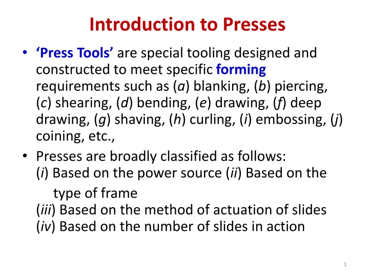
Introduction to Presses Press Tools are special tooling designed and constructed to meet specific forming requirements such as (a) blanking, (b) piercing, (c) shearing, (d) bending, (e) drawing, (f) deep drawing, (g) shaving, (h) curling, (i) embossing, (j) coining, etc., Presses are broadly classified as follows: (i) Based on the power source (ii) Based on the type of frame (iii) Based on the method of actuation of slides (iv) Based on the number of slides in action 1
CLASSIFICATION BASED ON POWER SOURCE Based on the power source, presses can be classified as: (a) Mechanical presses (b) Hydraulic presses. 2
In most mechanical presses, a flywheel is the major source of energy that is applied to the slides by cranks, gears, eccentric or linkages. The flywheel runs continuously and is engaged by the clutch only when a press stroke is needed. 4
In basic operation of a hydraulic press consists of applying hydraulic pressure at one end of a piston sliding inside a cylinder. The hydraulic press can be used to apply an enormous force of up to 50,000 tonnes. The press can also deploy longer strokes as well as variable strokes enabling deep drawing operations. Hydraulic presses generally have the following items to make up for the complete system: (i) High-pressure hydraulic pump (iii) Oil storage tank (ii) Accumulator (iv) Solenoid actuated values 5
(v) Cylinders and piston assemblies (separate cylinder and piston assemblies are used for the main punching operation and for the die cushion assembly) (vi) Pressure switches (vii) Pressure gauges (viii) Filter (ix) Interconnecting pipeline Based on the type of press frame, presses can be classified as: (a) Gap-frame presses (b) Straight-side presses. 6
CLASSIFICATION BASED ON METHOD OF ACTUATION OF SLIDE The most widely used mechanisms in operation of these presses are: (a) Crank shafts (b) Eccentric shafts (c) Knuckle lever drives (e) Toggle mechanisms (d) Rocker arm drives 7
CLASSIFICATION BASED ON THE NUMBER OF SLIDES IN ACTION Based on number of slides, presses can be classified as (a) one-slide, (b) two-slide, and (c) three-slide presses, which are referred to as single-, double- and triple action presses. Single-action press has one reciprocating slide acting against a fixed bed. Generally, used in metal stamping operations such as blanking, embossing, coining and drawing. Double-action press has two reciprocating slides acting in the same direction. 10
Introduction to Press Tools A press tool is a device that enables any one of the operations such as blanking, piercing, bending, and drawing to be performed repeatedly in mass- scale in a press. In some occasions, operations like blanking and bending, blanking and drawing or piercing and blanking can be carried out in tandem, calling for specialized press tools. Since the punch or a die are the two major components in a press tool, which are subjected to severe loads and hence wear and tear, they are designed to be replaced, retaining the body of the press tool as a standard device in a press tool. 11
A Die Set consists of the following components: Die Shoe, which holds the die by means of a set of screws and dowels. They are designed to withstand the severe impact loads transmitted to the die. They have flanges protruding on the two ends, to facilitate fastening the die set to the bolster plate of the press. (A bolster plate is a rugged and heavy member of the press over which the press tool is mounted). 12
Punch holding plate, which moves up and down the guiding pins and which carries the punch. The shank is a member in the die set to which the punch plate is fitted. This is also fastened to the ram of the press and is a transmitting member of the reciprocating motion down to the component. Guiding pins having bushes are vertical pins about which the punch holder plate and hence the punch, moves vertically. These are fitted to the die shoe. Guiding pins can be two, three or four in number, depending on the application. 13
One important parameter in the design and selection of die set is the shut height . This is nothing but the vertical height of the die set, between the bottom of the die shoe and the punch holder, measured when the device is in closed position. Die sets are generally made up of cast steel, forged steel or rolled steel. 14
DESCRIPTION OF PRESS TOOLS The Blanking/Piercing/Bending/Drawing Punch Major function The basic function is to produce the desired quantity of components, whether it is blanking, bending or drawing, with the specified quality. As the punchis the main member, which imparts the required force of the press, the same needs to be manufactured out of the material which has toughness, strength and wear resistance properties. Clearances between the punch and the die play a vital role in the life of this component, which depends upon the thickness of the workpiece as well as the ductility of the component 17
PUNCHES Plain punches are plain hardened tool steel blocks, which are fastened to the punch plates. Pedestal punches are sometimes called Flanged punches because they are machined from a block of steel such that the punch has flanges all around. Perforated punches are standard punches, which are usually less than 25 mm in diameter and are straight away screwed to the punch holder plate. The advantage of using these punches is that they can be removed and fitted without the removal of the punch holder plate. 18
Punch material depends on the material of the strip, its thickness and overall size. However, tool steels with high nickel are chosen because they retain hardness in high temperatures, and have strength, wear resistance and toughness to withstand crack propagation. 19


