Introduction to PLC Analog Signal Input Modules
In industrial automation, analog signals play a crucial role in transmitting measuring units. The Delta DVP-04AD-S module converts external analog input signals into 14-bit digital values for PLC operations. With voltage input ranging from -10 to 10V and current input from -20 to 20mA, this module ensures precise data conversion and control. Learn about the features and functionality of analog signal input modules in PLC systems for efficient automation processes.

Download Presentation

Please find below an Image/Link to download the presentation.
The content on the website is provided AS IS for your information and personal use only. It may not be sold, licensed, or shared on other websites without obtaining consent from the author.If you encounter any issues during the download, it is possible that the publisher has removed the file from their server.
You are allowed to download the files provided on this website for personal or commercial use, subject to the condition that they are used lawfully. All files are the property of their respective owners.
The content on the website is provided AS IS for your information and personal use only. It may not be sold, licensed, or shared on other websites without obtaining consent from the author.
E N D
Presentation Transcript
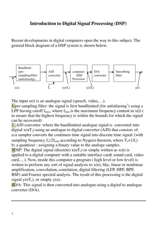
Delta DVP-04AD-S The A/D Conversion In industrial automation, many measuring units are transmitted by analog signals. The most frequently adopted range for the signals are voltage -10 ~ 10V and current -20 ~ 20mA. To use the analog signals as the parameters for PLC operations, you have to convert them into digital values first. For example, the voltage -10 ~ 10V is first converted into values -8,000 ~ +8,000 by an A/D module, and the PLC will read/write the control registers (CR) in the AD module by FROM/TO instructions. The signals sent back to the PLC for operations will be digital K-8,000 ~ K8,000.
Features: DVP04AD (or DVP06AD) analog signal input module receives external 4 (or 6) points of analog input signals (voltage or current) and converts them into 14-bit digital signals. The CPU can read/write the data in the module by using FROM/TO instructions in the program. There are 49 16-bit control registers in the module. You can select voltage input or current input by the wiring. Range for voltage input: 10V ( 8,000, resolution: 1.25mV). Range for current input: 20mA ( 4,000, resolution: 5 A).