Interconnection Networks in Multiprocessing Systems Overview
Explore the intricacies of interconnection networks for multiprocessing systems in Embedded Computer Architecture, covering connecting processors, topologies, routing, deadlock, switching, and performance metrics like bandwidth and latency. Delve into various network types, such as on-chip networks (NoC), MESH topology examples, and communication models like point-to-point, multicast, and broadcast.
Download Presentation

Please find below an Image/Link to download the presentation.
The content on the website is provided AS IS for your information and personal use only. It may not be sold, licensed, or shared on other websites without obtaining consent from the author.If you encounter any issues during the download, it is possible that the publisher has removed the file from their server.
You are allowed to download the files provided on this website for personal or commercial use, subject to the condition that they are used lawfully. All files are the property of their respective owners.
The content on the website is provided AS IS for your information and personal use only. It may not be sold, licensed, or shared on other websites without obtaining consent from the author.
E N D
Presentation Transcript
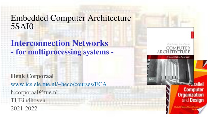
Embedded Computer Architecture 5SAI0 Interconnection Networks - for multiprocessing systems - Henk Corporaal www.ics.ele.tue.nl/~heco/courses/ECA h.corporaal@tue.nl TUEindhoven 2021-2022 Embedded Computer Architecture 1
Overview Connecting multiple processors or processing elements How to connect? Topologies Routing Deadlock Switching Performance: Bandwidth and Latency Supplementary (background) material: H&P Appendix F Dubois Chapter 6 Embedded Computer Architecture 2
Parallel computer systems M M M L2 Cache Interconnection network Interconnection network L1 L1 L1 CMP CMP CMP P P P Interconnect between processor chips (system area network--san) Interconnect between cores on each chip = Network On Chip -- NOC Other Networks, not covered: WAN (wide-area network), your connection with the outsie world LAN (local area network), e.g. your home network Embedded Computer Architecture 3
1. Network (switched) or 2. Bus (shared resource ) 1. Network: claimed to be more scalable no bus arbitration point-to-point connections Disadvantage: router overhead Example: NoC with 2x4 mesh routing network node node node node R R R R node node node node R R R R Embedded Computer Architecture 4
NW Example: MESH topology Switch N.I. Node Switch B Link A Connects nodes: cache and modules, processing elements, processors, Nodes are connected to switches through a network interface (NI) Switch: connects input ports to output ports Link: wires transferring signals between switches Links Width and Clock rate determine Bandwidth Transfer can be synchronous or asynchronous From A to B: hop from switch to switch Decentralized (direct) Embedded Computer Architecture 5
Simple communication model Machine B Machine A out-buffer in-buffer in-buffer out-buffer POINT-TO-POINT REQUEST/REPLY E B F A C G MULTICAST BROADCAST D Point-to-point message transfer Request / Reply: request carries ID of sender Multicast: one to many Broadcast: one to all Embedded Computer Architecture 6
Messages and packets Messages contain the information transferred Messages are broken down into packets Packets are sent one by one Payload: the actual message contents Header/trailer: contains information to route packet Error Correction Code: ECC to detect and correct transmission errors Embedded Computer Architecture 7
1. Network (switched) or 2. Bus (shared resource) 2. Bus = set of parallel wires connecting everybody All-to-All connection via shared medium Supports broadcast communication, i.e. 1 => All communication Needs bus arbitration Centralized vs distributed arbitration Line (wire) multiplexing (e.g. address & data) Pipelining For example: arbitration => address => data Split-transaction bus vs Circuit-switched bus Properties: Centralized (indirect) Low cost Shared Low bandwidth (single hop), under low utilization ADDRESS DATA CONTROL ARBITRATION Embedded Computer Architecture 8
Design Characteristics of a Network Topology (how things are connected): Crossbar, ring, 2-D and 3-D meshes or torus, hypercube, tree, butterfly, perfect shuffle, .... Routing algorithm (path used): Example in 2D torus: first east-west, then north-south (avoids deadlock) Switching strategy: Circuit switching: full path reserved for entire message, like the telephone. Packet switching: message broken into separately-routed packets, like the post office. Flow control and buffering (what if there is congestion): Stall, store data temporarily in buffers re-route data to other nodes tell source node to temporarily halt, discard, etc. QoS (quality of service) guarantees Error handling etc, etc. Embedded Computer Architecture 9
Switch / Network: Topology Topology determines important metrics: Degree: number of links from a node Diameter: max number of links crossed between nodes Average distance: number of links to random destination Bisection bandwidth = link bandwidth * bisection Bisection = minimum number of links that separate the network into two halves Embedded Computer Architecture 10
Bisection Bandwidth Bisection bandwidth = bandwidth across smallest cut that divides network into two equal halves ~ Bandwidth across narrowest part of the network not a bisection cut bisection cut bisection bw= link bw bisection bw = sqrt(n) * link bw Bisection bandwidth is important for algorithms in which all processors need to communicate with all others Embedded Computer Architecture 11
Linear and Ring Topologies Linear array Diameter = n-1; average distance ~n/3 Bisection bandwidth = 1 (in units of link bandwidth) Torus or Ring Diameter = n/2; average distance ~ n/4 Bisection bandwidth = 2 Natural for algorithms that work with 1-D arrays Embedded Computer Architecture 12
Meshes and Tori Two dimensional mesh Diameter = 2 * (sqrt( n ) 1) Bisection bandwidth = sqrt(n) Two dimensional torus Diameter = sqrt( n ) Bisection bandwidth = 2* sqrt(n) Generalizes to higher dimensions Natural for algorithms that work with 2D and/or 3D arrays Embedded Computer Architecture 13
Hypercubes Number of nodes n = 2d for dimension d Diameter = d Bisection bandwidth = n/2 0d 1d 2d 3d 4d Popular in early machines (Intel iPSC, NCUBE, CM) Lots of clever algorithms Extension to: k-ary n-cubes (k nodes per dimension, so kn nodes) 110 111 010 011 100 101 Greycode addressing: Each node connected to others with 1 different address bit 000 001 Embedded Computer Architecture 14
Trees Diameter = log n. Bisection bandwidth = 1 Easy layout as planar graph Many tree algorithms (e.g., summation) Fat trees avoid bisection bandwidth problem: More (or wider) links near top Example: Thinking Machines CM-5 (next slide) Embedded Computer Architecture 15
Fat Tree example A multistage fat tree (CM-5) avoids congestion at the root node Randomly assign packets to different paths on way up to spread the load Increase degree near root, decrease congestion Embedded Computer Architecture 16
Crossbar Requires n2 switches (very costly) Diameter = 1 !! Embedded Computer Architecture 17
Multistage Networks: Butterflies with n = (k-1)2k switches Connecting 2k processors, with Bisection bandwidth = 2*2k Cost: lots of wires 2log(k) hop-distance for all connections, however blocking possible Used e.g. in BBN (Bolt, Beranek and Newman) Butterfly, in 1980s Natural for FFT (fast fourier transform) Butterfly 2x2 Switch PE O 1 O 1 O 1 O 1 4x4 Butterfly switch made of 4x (2x2) switches Multistage butterfly network: k=3 (connecting 8 PEs with 3 stages) Embedded Computer Architecture 18
Routing in butterflies: Omega NW Use source and/or destination addresses 0 0 USE THE DESTINATION ADDRESS IN THIS CASE, 3 BITS <d2,d1,d0> 1 1 USE ith BIT OF THE DESTINATION (di) TO SELECT UPPER OR LOWER OUTPUT PORT FOR STAGE n-1-i 0 => UP 1 => DOWN 2 2 3 3 4 4 5 5 EXAMPLE: ROUTE FROM 4 TO 6 DESTINATION ADDRESS IS 110 DOWN IN STAGE 0 DOWN IN STAGE 1 UP IN STAGE 2 ( = 110 ) 6 6 7 7 STAGE 2 STAGE 0 STAGE 1 Embedded Computer Architecture 19
Comparison between topologies Interconnection network Crossbar switch Switch degree N Network diameter 1 Bisection width N Network size N Butterfly (built from k- by-k switches) k-ary tree k logk N N/2 N k+1 2logk N 1 N Linear array 2 N-1 1 N Ring 2 N/2 2 N n-by-n mesh 4 2(n-1) n N=n2 n-by-n torus 4 n= N 2n N=n2 k-dimensional hypercube k-ary n-cube k k=log2 N 2k-1 N=2k 2k nk/2 2kn-1 N=nk NW Metrics: Switch degree: Network diameter: Bisection width: Network size: (max) # of ports for each switch (switch complexity) worst-case routing distance between any two nodes # of links in bisection (worst-case bandwidth) # of nodes Embedded Computer Architecture 20
Routing algorithm: Dimension-order Routing Route 1-dimension at a time, e.g. first x then y-dim Deterministic routing (only 1 option) Embedded Computer Architecture 21
Deadlock: when possible? 4 necessary conditions for deadlock, given a set of agents accessing shared resources: Mutual exclusion Only one agent can access the resource at a time Hold and wait Agent holds on its acquired resources while waiting for others No preemption No mechanism can force agent to relinquish acquired resource Circular wait A set of agents wait on each other to acquire each others resources => no one can make any progress shared resources can be SW or HW: critical code sections, disk, printer, .. In NW: Agents = packets; resources = physical or logical channels Embedded Computer Architecture 22
Deadlock avoidance Assume Mesh or Tori Assume that packets are free to follow any route In this example each node is trying to send a packet to the diagonally opposite node at the same time: (0,0) (1,1), (0,1) (1,0), etc. To avoid link conflicts, (1,0) uses c3 then c0, and (0,0) uses c0 then c1, etc... The resource acquisition graph (or channel-dependency graph) on the right shows circular wait => DEADLOCK Possible Embedded Computer Architecture 23
Deadlock avoidance No circular dependency! Enforce dimension-order routing (xy-routing) Packet moves first horizontally, then vertically No cycle possible!!! However: this restricts routing, and could result into more congestion on the channels Alternative to avoid deadlocks: use virtual channels E.g.: support an alternate set of channels in which yx routing is enforced e.g., c1 If c3 is occupied, the packet can safely route through c0 and c1 Embedded Computer Architecture 24
Switch micro-architecture, supporting virtual channels Physical channel = link Virtual channel = buffers + link link is time-multiplexed among flits One buffer per virtual channel Embedded Computer Architecture 25
Switching strategy: how are connections established in the NW ? Circuit switching = Establish a connection for the duration of the network service Example: circuit switching in mesh Establish path in network Transmit (many) packets Release path Low latency; high bandwidth, but requires (long) path set-up time Good when packets are transmitted continuously between two nodes Packet switching = Every packet includes destination address, and finds its own route Example: remote memory access on a bus Send a request packet to remote node Release bus while memory access takes place Remote node sends reply packet to requester In between send and reply, other transfers are supported Example: remote memory access on a mesh Embedded Computer Architecture 26
Switching strategies: how are packets forwarded store-and-forward = packets move from node to node and are stored in buffers in each node this increases the transmission time (see next slide). cut-through = packets move through nodes in pipelined fashion, so that the entire packet moves through several nodes at one time Two implementations of cut-through: Virtual cut-through switching: The entire packet is buffered in the node when there is a transmission conflict When traffic is congested and conflicts are high, virtual cut through behaves like store-and- forward Wormhole switching: Each node has enough buffering for a flit (flow control unit) A flit is made of consecutive phits (physical transfer unit) A phit basically is the width of a link (= number of bits transferred per clock) A flit is a fraction of the packet, so the packet can be stored in several nodes (one or more flits per node) on its path Info: see books, and e.g. http://pages.cs.wisc.edu/~tvrdik/7/html/Section7.html https://en.wikipedia.org/wiki/Wormhole_switching Embedded Computer Architecture 27
Latency models 1. 2. Sender Overhead (SO): creating the packet and moving it to NI (Network Interface) Time of Flight (ToF): time to send a bit from source to destination when the route is established and without conflicts; this includes switching time ToF can include buffering time at switches (as in store-and-forward or virtual cut-through) Transmission Time (TT): time to transfer a packet from source to destination, once the first bit has arrived at destination phit: number of bits transferred on a link per cycle, so Link BW = phit*freqlink Transmission time = packet size/phit size note: a flit = unit of flow control (over a link), containing 1 or more phits Routing Time (RT): time to set-up route (as in circuit switching), or setting switches (in packet switching) Receiver Overhead (RO): time to strip packet and move it out of the input buffer (of the NI) 3. 4. 5. Embedded Computer Architecture 28
Packet latency calculation Packet send from A to B: size = 100 bytes circuit-switching route set-up: 200ns distancy (A to B) = 9 hops phit = 10 bits, tcycle = 8ns sender and receiver overhead each 12ns Q: what is the total latency, Lpacket, required to send this packet? 12ns 12ns B A 10ns 10ns 10ns 10 switches => 9 hops ( or links) Answer (see figure): Lpacket = SO+ ToF + TT +RT + RO = 12ns + 9*10ns + 800 bits/(10bits/8ns) + 200ns + 12 ns = 12ns + 90 ns + 640ns + 200ns + 12ns = 954 ns Note: BWlink = 10bits/8ns = 1.25 Gbps Embedded Computer Architecture 29
Message sending latency Message contains n packets Transfer of these packets can be pipelined: Transfer pipeline has 3 stages: Sender overhead --> Transmission --> Receiver overhead Total message time, Lmessage= time for the first packet + (n-1)/pipeline throughput End-to-end message latency, Lmessage, a message contains multiple (n) packets: Lmessage = Sender Overhead + Time of Flight + Transmission Time + Routing Time + Receiver Overhead (n-1) * Max(Sender Overhead, Transmission Time, Receiver Overhead) Lmessage = SO + ToF + TT + RT + RO + (n-1)*Max(SO, TT, RO) Embedded Computer Architecture 30
Message latency calculation Message Message of 10 packets Transmission Time = 100 ns Sender/receiver overhead = 110/80 ns Time of Flight = 20ns, including switching time Assume that Routing time, RT = 0ns Q: what is total transfer time? P P P P P P P P P P 80ns 110ns, per packet B A ToF = 20 ns, TT = 100ns per packet Lmessage = Note: sender overhead is the main bottleneck SO + ToF + TT + RT + RO + (n-1)*Max(SO, TT, RO) = 110ns + 20ns + 100ns + 0ns + 80ns + (n-1)*Max(110,100,80) ns = 110 + 20 + 100 + 0 + 80 + 9*110 ns = 1300 ns Q (do it yourself): what is Lmessage if you send a message with 10 packets of previous example (slide 28) ? Embedded Computer Architecture 31
Message effective BW calculation Message Message of n packets, each 15 bytes payload Transmission Time = 100 ns Sender/receiver overhead = 110/80 ns Time of Flight = 20ns, including switching time Routing time is zero Q: what is the effective bandwith when sending 10, what if sending many packets? P P P P P P P P P P 80ns 110ns, per packet B A ToF = 20 ns, TT = 100ns per packet BWeffective, 10 packets = BWeffective, many packets = payload size/transmission latency = 10*15 bytes/1300ns = 115 Mbyte/sec = 0.92 Gbps packet size / Max (SO, TT, RO) 15 bytes / Max (110ns, 100ns, 80ns) = 15 bytes/110ns = 136 MByte/sec = 1.09 Gbps Note: sender overhead is the main bottleneck Embedded Computer Architecture 32
What did you learn on NOCs ? The main interconnect topologies and their properties Several routing protocols Deadlock conditions, how to avoid it Switching protocols circuit vs packet switching store-and-forward vs (virtual) cut-through Network metrics comparing metrics of various networks: Diameter, Bi-section BW, Degree, Cost (~ nr of switches * degree) Calculate effective BW and Latencies Embedded Computer Architecture 33
