Integration Capacity Analysis


Integration Capacity Analysis
Limited Generation Profile
October 27, 2022


Agenda
•
Generation ICA Overview
•
Generation ICA Modeling Methodology
•
LGP and ICA Buffer
•
Q&A
2
CPUC Decision (D.) 17-09-023:
•
Integration Capacity Analysis (ICA) to address the primary interconnection use
case of aiding Distributed Energy Resource (DER) developers in identifying
interconnection locations where projects are less likely to trigger distribution
upgrades and providing ICA data that can be relied upon to streamline Rule 21
interconnection.
•
The Distribution Resources Plan (DRP) proceeding was responsible for the methodological
development of ICA and the publication of ICA data and maps.
•
Currently, ICA is ruled under High DER Proceeding.
•
IOUs update their ICA portals and data on a monthly basis.
3
Regulatory Background – DRP (High DER)
4
Steady State Voltage
Amount of generation which can be installed without causing primary voltage to result in a
deviation from Rule 2 limits at the customer premise. Rule 2 customer service voltage
limits are 5% of the nominal voltage (i.e. 114-126 V on a 120 V base).
Voltage Variation
Amount of generation which can be installed without causing unacceptable variation in voltage levels.
Thermal
Cable, conductor, and equipment ratings establish the thermal limits. In cases where the
ICA results exceed circuit or substation transformer bank ratings, the ICA results will be
reduced to the circuit or substation transformer bank rating.
Uniform Generation ICA
The uniform Gen ICA results represent the maximum uniform generation at the point of interconnection without
violating the thermal, voltage variation, protection, steady state voltage criteria, and reverse power flow.
ICA Criteria & Methodology
Protection
Checks for minimum fault level
Reverse Power Flow
Checks for reverse power flow through substation transformer and operational flexibility
No additional buffer
values are built into the
ICA
prior to publication.
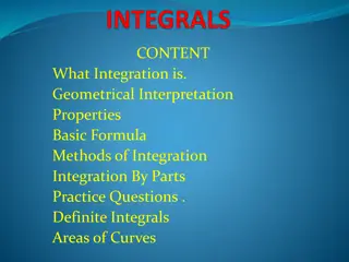
ICA Iterative Methodology
5
•
Rule 21 Screen M Use Case
•
All Interconnecting DERs to be evaluated against the ICA values as a part of Screen M
•
Rule 21 Limited Generation Profile Use Case
•
Allow Interconnecting DER to Be Evaluated and Operate Under Limited Generation Profile. This
proposal would Modify interconnection procedures to allow a DER customer to submit a “Limited
Generation Profile” as part of their Interconnection Application, require that customer to enable
generation profile limiting functionality, and allow utility limited future opportunity to alter that profile
if circumstances warrant
•
Limited Generation Profile (LGP) would be applied
when requested by the interconnecting DER
customer
6
Rule 21 Use Cases with Gen ICA
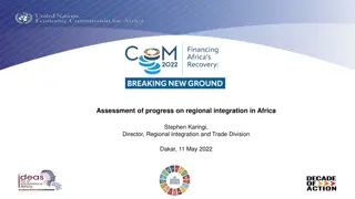
Limited Generation Profile
As shown on the graph, the GF Net export is 2.0 MW which is higher than 1.14MW (lowest
ICA-SG value in the ICA-SG profile). Customer
can choose to request using
LGP to operate
within the lower limits of April, September
and October.
7
8
Q&A and Discussions
This presentation delves into the Integration Capacity Analysis (ICA) process, which aids Distributed Energy Resource (DER) developers in identifying interconnection locations. The slides cover the regulatory background, ICA criteria and methodology, iterative methodology, Rule 21 use cases with Gen ICA, and more.

Download Presentation

Please find below an Image/Link to download the presentation.
The content on the website is provided AS IS for your information and personal use only. It may not be sold, licensed, or shared on other websites without obtaining consent from the author.If you encounter any issues during the download, it is possible that the publisher has removed the file from their server.
You are allowed to download the files provided on this website for personal or commercial use, subject to the condition that they are used lawfully. All files are the property of their respective owners.
The content on the website is provided AS IS for your information and personal use only. It may not be sold, licensed, or shared on other websites without obtaining consent from the author.
E N D
Presentation Transcript
Integration Capacity Analysis Integration Capacity Analysis Limited Generation Profile October 27, 2022 READ AND DELETE For best results with this template, use PowerPoint 2003 Public
Agenda Generation ICA Overview Generation ICA Modeling Methodology LGP and ICA Buffer Q&A 2 Public
Regulatory Background DRP (High DER) CPUC Decision (D.) 17-09-023: Integration Capacity Analysis (ICA) to address the primary interconnection use case of aiding Distributed Energy Resource (DER) developers in identifying interconnection locations where projects are less likely to trigger distribution upgrades and providing ICA data that can be relied upon to streamline Rule 21 interconnection. The Distribution Resources Plan (DRP) proceeding was responsible for the methodological development of ICA and the publication of ICA data and maps. Currently, ICA is ruled under High DER Proceeding. IOUs update their ICA portals and data on a monthly basis. 3 Public
ICA Criteria & Methodology Steady State Voltage Amount of generation which can be installed without causing primary voltage to result in a deviation from Rule 2 limits at the customer premise. Rule 2 customer service voltage limits are 5% of the nominal voltage (i.e. 114-126 V on a 120 V base). No additional buffer values are built into the ICA prior to publication. Thermal Cable, conductor, and equipment ratings establish the thermal limits. In cases where the ICA results exceed circuit or substation transformer bank ratings, the ICA results will be reduced to the circuit or substation transformer bank rating. Voltage Variation Amount of generation which can be installed without causing unacceptable variation in voltage levels. Protection Checks for minimum fault level Reverse Power Flow Checks for reverse power flow through substation transformer and operational flexibility Uniform Generation ICA The uniform Gen ICA results represent the maximum uniform generation at the point of interconnection without violating the thermal, voltage variation, protection, steady state voltage criteria, and reverse power flow. 4 Public
ICA Iterative Methodology 5 Public
Rule 21 Use Cases with Gen ICA Rule 21 Screen M Use Case All Interconnecting DERs to be evaluated against the ICA values as a part of Screen M Rule 21 Limited Generation Profile Use Case Allow Interconnecting DER to Be Evaluated and Operate Under Limited Generation Profile. This proposal would Modify interconnection procedures to allow a DER customer to submit a Limited Generation Profile as part of their Interconnection Application, require that customer to enable generation profile limiting functionality, and allow utility limited future opportunity to alter that profile if circumstances warrant Limited Generation Profile (LGP) would be applied when requested by the interconnecting DER customer 6 Public
Limited Generation Profile As shown on the graph, the GF Net export is 2.0 MW which is higher than 1.14MW (lowest ICA-SG value in the ICA-SG profile). Customer can choose to request using LGP to operate within the lower limits of April, September and October. Month Limits Jan Feb Mar Apr May Jun Jul Aug Sept Oct Nov Dec 2.00 2.00 2.00 1.53 2.00 2.00 2.00 2.00 1.79 1.14 2.00 2.00 January February March April May June July August September October November December Monthly Schedule 7 Public
PGE SCE SDGE 90th and 10th percentile loading based on circuit- level shapes and AMI load 90th and 10th percentile loading based on circuit- level shapes and SCADA/AMI load Loading Conditions Circuit-level: Generate 576 profile from one year of 8,760 historical data AMI-level: 90th and 10th percentile loading Circuit Voltage Profiles are developed by obtaining the maximum voltage reading at the substation transformer bank coincident with the 576 circuit load profile. The voltage profiles are then capped to 0.96 to 1.04 of the nominal voltage to clear any preexisting conditions which may prevent the ICA from being performed. Existing PV assumed to be generating based on typical PV profiles Other technologies assumed to be generating at 100% of nameplate Queued generation is modeled in Gen ICA Regulators and switched capacitors allowed to float based on settings Voltage Conditions Bank-level loading is used to develop settings that output 122 V at minimum loading and 126 V at maximum loading. At each hour, the base-case loading level is used to specify what the output voltage is for that hour for circuit-level analysis. A flat 120V voltage profile is assumed. Substation voltage regulators are allowed to float based on local settings Existing Distributed Generation Assumptions Interconnected distributed generation is modeled as it materializes in metered net load. Queued generation is modeled in Gen ICA Existing PV assumed to be generating based on typical PV profiles Other technologies assume 100% of nameplate. Equipment Assumptions Regulators and switched capacitors allowed to float based on local settings in base case, locked in ICA Limits are consistent with planning process, and cap at circuit and bank capability limits post- process Accounts for other limitations such as underground cable temperature and protective devices in the field (83% of the phase overcurrent value) 3 V (2.5%) limit on 120 V base Regulators and switched capacitors allowed to float based on local settings Thermal Limitations Limits are consistent with planning process, and cap at circuit capability limits post-process, where applicable Does not currently account for underground cable temperature limitations. Analysis incorporates both equipment limitations and planning limits for circuits and banks Does not account for other limitations such as underground cable temperature and protective devices in the field Voltage Variation Limitations Steady-state Primary Voltage Limitations 3.6 V (3%) limit on 120 V base 3.6 V (3%) limit on 120 V base Acceptable voltage: 118.0-126.5 V Acceptable voltage: 114-126 V Considering increasing lower bound to 118 V to account for secondary voltage drop Acceptable voltage: 116-126 V 8 Public


")