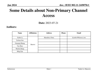
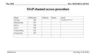
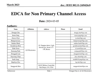
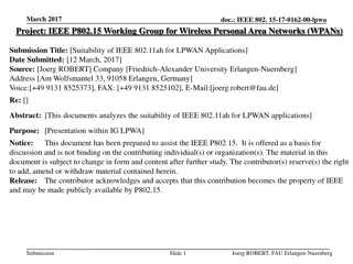
IEEE 802.11-20/1045r0 Channel Access Design Details
This contribution delves into the design of channel access for IEEE 802.11-20/1045r0, focusing on slot structure, EDCA parameters, terms, and general descriptions. It outlines the time division, slot types, EDCA parameters for regular and prioritized traffic, AP-advertised parameters, and the assumed P-traffic pattern. The content elucidates slot assignments, service periods, and prioritized access during P-slots.

Download Presentation

Please find below an Image/Link to download the presentation.
The content on the website is provided AS IS for your information and personal use only. It may not be sold, licensed, or shared on other websites without obtaining consent from the author.If you encounter any issues during the download, it is possible that the publisher has removed the file from their server.
You are allowed to download the files provided on this website for personal or commercial use, subject to the condition that they are used lawfully. All files are the property of their respective owners.
The content on the website is provided AS IS for your information and personal use only. It may not be sold, licensed, or shared on other websites without obtaining consent from the author.
E N D
Presentation Transcript
Data Converters EECT 7327 Integration ADC Professor Y. Chiu Fall 2014 Integration ADC 1
Data Converters EECT 7327 Integration ADC Professor Y. Chiu Fall 2014 Single-Slope Integration ADC VY Vi VX Control Counter Do fclk I C Sampled-and-held input (Vi) Counter keeps counting until comparator output toggles Simple, inherently monotonic, but very slow (2N*Tclk/sample) 2
Data Converters EECT 7327 Integration ADC Professor Y. Chiu Fall 2014 Single-Slope Integration ADC slope=I/C VX t I V = t , D = 1 i 1 o C T clk t V D = , i I T o VY clk C I T t1 LSB= clk C t start stop INL depends on the linearity of the ramp signal Precision capacitor (C), current source (I), and clock (Tclk) required Comparator must handle wide input range of [0, VFS] 3
Data Converters EECT 7327 Integration ADC Professor Y. Chiu Fall 2014 Dual-Slope Integration ADC C R Vi -VR VX Control Counter Do fclk RC integrator replaces the I-C integrator Input and reference voltages undergo the same signal path Comparator only detects zero crossing 4
Data Converters EECT 7327 Integration ADC Professor Y. Chiu Fall 2014 Dual-Slope Integration ADC VX Vos t1 t2 V V RC V = t = t i R t m 1 2 RC V V t t N N D = = = i 2 2 Vm o 1 2 R 1 1 or D =N for fixed N o 2 1 Exact values of R, C, and Tclk are not required Comparator offset doesn t matter (what about its delay?) Op-amp offset introduces gain error and offset (why?) Op-amp nonlinearity introduces INL error 5
Data Converters EECT 7327 Integration ADC Professor Y. Chiu Fall 2014 Op-Amp Offset Vi = 0 Vi = VR VX 0 VX 0 t1 t2 t1 t2 t t N2 0 Offset Longer integration time! Do Actual Ideal Dos 0 VR Vi 6
Data Converters EECT 7327 Integration ADC Professor Y. Chiu Fall 2014 Subranging Dual-Slope ADC Vt SHA Cmp1 Vi VX CS Cnt 1 (8 bits) Carry Cmp2 MSB s Control Logic fclk Cnt 2 (8 bits) LSB s I I 256 MSB discharging stops at the immediate next integer count past Vt Much faster conversion speed compared to dual-slope Two current sources (matched) and two comparators required 7
Data Converters EECT 7327 Integration ADC Professor Y. Chiu Fall 2014 Subranging Dual-Slope ADC ( ) dV 1 I, C X dt = VX 1 2 ( ) 2 dV I X dt = 256C Vt t = + D N W N o 1 2 t1 t2 Precise Vt is not required if carry is propagated Matching between the current sources is critical if I1 = I, I2 = (1+ ) I/256, then | | 0.5/256 It d be nice if CMP 1 can be eliminated ZX detector! 8
Data Converters EECT 7327 Integration ADC Professor Y. Chiu Fall 2014 Subranging Dual-Slope ADC CMP 1 response time is not critical Delay from CNT 1 to MSB current shut-off is not critical constant delay results in an offset (why?) CMP 2 response time is critical, but relaxed due to subranging 9
Data Converters EECT 7327 Integration ADC Professor Y. Chiu Fall 2014 Subranging Multi-Slope ADC SHA Vi Cnt 1 4 Bits VX CS Control Logic Cnt 2 4 Bits fclk Cnt 3 4 Bits I I I 16 256 Ref: J.-G. Chern and A. A. Abidi, An 11 bit, 50 kSample/s CMOS A/D converter cell using a multislope integration technique, in Proceedings of IEEE Custom Integrated Circuits Conference, 1989, pp. 6.2/1-6.2/4. 10
Data Converters EECT 7327 Integration ADC Professor Y. Chiu Fall 2014 Subranging Multi-Slope ADC ( ) dV 1 I, C VX X dt = 1 2 3 ( ) 2 dV I X dt = , 16C I 256C t ( ) 3 dV X dt = t1 t2 t3 = + D N W N W N o 1 1 2 2 3 Single comparator detects zero-crossing Comparator response time greatly relaxed Matching between the current sources still critical 11
Data Converters EECT 7327 Integration ADC Professor Y. Chiu Fall 2014 Subranging Multi-Slope ADC Comparator response time is not critical except the last one Delays from CNTs to current sources shut-off are not critical constant delays only result in offsets Last comparator response time is critical, but relaxed due to multi- step subranging 12