Fascinating World of Radio Direction Finding (RDF) Through History
Explore the intriguing world of Radio Direction Finding (RDF), an essential technique for determining the direction of radio signals. From its origins with Heinrich Hertz in 1888 to its pivotal role in military operations during WWI and WWII, RDF technology has evolved over the years while still relying on the skills of operators. Learn about its applications in identifying interference sources, localizing transmitters, military and security operations, civilian search and rescue, wildlife tracking, and more.
Download Presentation

Please find below an Image/Link to download the presentation.
The content on the website is provided AS IS for your information and personal use only. It may not be sold, licensed, or shared on other websites without obtaining consent from the author.If you encounter any issues during the download, it is possible that the publisher has removed the file from their server.
You are allowed to download the files provided on this website for personal or commercial use, subject to the condition that they are used lawfully. All files are the property of their respective owners.
The content on the website is provided AS IS for your information and personal use only. It may not be sold, licensed, or shared on other websites without obtaining consent from the author.
E N D
Presentation Transcript
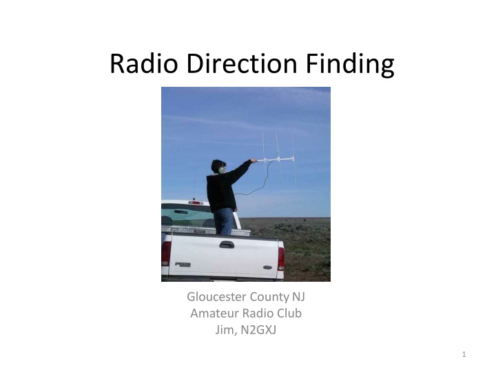
Radio Direction Finding Gloucester CountyNJ Amateur Radio Club Jim, N2GXJ 1
What is RDF? RDF Radio Direction Finding Determining the direction from which a received radio signal was transmitted. Technology has changed over the decades Essential elements of the techniques have not Success is still largely up to the skill of the RDF equipment operator 2
When RDF? Searching for sources of radio interference Localizing non-authorized transmitter Identification of transmitters, known and unknown Dealing with spread spectrum techniques, especially in wireless communications Military and security forces Civilian search and rescue Wildlife tracking Radiosport! 3
History DF technique is as old as radio Heinrich Hertz (1888) experiments with de cimetric waves found antenna directivity Earlypatents Stone,1902 Forest, 1909 Belini and Tosi, 1909 Adcock, 1919 4
History -WWI DF widely used to pinpoint enemy forces during WWI Radio Compass ,prototype for U.S. Navy 1916 Passivetechnology, listen in on large military forces keeping in contact with theirheadquarters Manual RDF techniques Rotatable antennas RF propagation challenges, groundwave, skywave, multi-path, fading, polarization changes, non-white external noise, seasonal and time-varyingionospherics, (don t weknow!) Kensington Maryland field station, circa 1919, NIST PhotographicCollection (http://museum.nist.gov/panels/gallery/radiodf.html) 5
History - WWII Accuracy improvement HF/DF Nets Multiple RDF stations operating together as a net Each try get directional fix on callsign heard, noting time and frequency, then coordinate with others Intercept lines drawn on map for all sites that got a fix on target Ref:http://www.researcheratlarge.com/Pacific/RDF/ 6
WWII, RDF Stories Pearl Harbor As shown in movie ToraToraTora ,Japan fleet used Honolulu broadcast station as an over-the-horizonbeaconfor attack on PearlHarbor RegularJapanese carrierradio operatorskept back in Tokyo, generating falsetraffic their unique styles recognized and located as being in home islands Secret Transmitters British Radio Security Service up to 1700 volunteer interceptors (radio amateurs) recruited to detect illicit transmissions Similar efforts in Europe by the Germans to locate resistance groups D-day Deceptions Operation Fortitude, with (fake) First US Army Group, led by George Patton. Radio trickery helped convince Germans real plan for invasion in Calais, notNormandy. U.S. Navy DAQ(WWII) GermanEP2a U-boats U-boat loop antenna technology, used in hunting Allied shipping (ref: http://uboat.net/articles/51.html) British ships outfitted with new automatic HuffDuff very effective in tracking and hunting short duration German submarine transmissions, helped turn the tide of shippinglosses German U-67 DFAntenna 7
Cold War After WWII From 1950 s, US adapted German Wullenweber antenna systems for use in Vietnam, cold-war eavesdropping (FRD-10, AN/FLR-9) Russians deployed similar (Krug), early use included tracking Sputnik OUTBOARD HF/DF systems standardized on U.S. Navy vessels New and ImprovedTechnologies Automatic signal search and analysis Combined active/passive systems (e.g. Over the horizon HF radar) Refs: http://www.answers.com/topic/radio-direction-finding-equipment AN /FLR-9, ref: http://en.wikipedia.org/wiki/Wullenweber http://www.enginee ringradio.us/blog/2010/10/how-the-cold-war-was-won 8
Modern Era Military (still) Search and Rescue Wildlife Tracking Spectrum enforcement Amateur RDF 9
Search and Rescue Cospas-Sarsat (satellite) compatible beacon frequencies 406.025 Mhz (digital burst,satellite) 121.5 MHz (analog, short rangehomer) 243. Mhz (old, phased out since2009) Other systems, not sostandard 457 kHz, Avalanchetransceiver 216-217 MHz, LoJack Safetynet & law enforcement trackingdevices Distress Radio Beacons Maritime(EPIRBs) Aircraft(ELTs) Personal (PLBs) What aboutAPRS(average packet delivery radio system) ? Has distress packet type, but not guarant eed & not satellite compatible 10
WildlifeTracking Tracking Micro-transmitters, collars, tagging technologies RDF techniques (fixed-wing, mobile, and on-foot) Studies Migrationpatterns Population studies Volunteeropportunities? 11
RDF Technologies Spectrum Enforcement If can t ID interfering signal by demodulation, or sig nal analysis, need radiolocation to locate source Radiolocation Technologies ManualTechniques Doppler DF Watson-Watt Time difference of arrival, SRDF(super resolution DF) 12
RDF Technology Manual Techniques Use of receiver and hand-helddirectional antenna Antenna is moved/rotatedto find directions of min and max signal strength, usually based on signalamplitude Home-in on signal by moving in direction of signal, then sweep to test possible locations in suspect area Can also plot bearing lines to triangulate general transmitter location Limitations: highly dependent on skill of operator, accuracy poor at distance, difficult to get bearing on short duration signals, difficult to get bearing on frequency agile signals Rohde & Schwarz portable monitoring & RDF 13
Homing-in by Bearing If mobile, can take bearing, follow it for a bit, then repeat Not always shortestpath 14
Triangulation Narrow search area by triangulating lines of bearing Take directional measurements from several locations Plot bearings on a map, narrow search to where bearings intersect Directional uncertainty at distance, progressively smaller hunt areas Max signal strength (S-meter) when close, attenuate to avoid overload 15
Watson-Watt Amplitude comparison technique, developed after WWII, using crossed loop, or Adcock antennas Enabled real-time RDF, even for short duration signals Difference signals from N-S, and W-E used to deflect el ectron beam on CRT BasicAdcock/Watson-Watt design is basis of many systems today 16
TDOA Time difference of arrival (TDOA) Works on detecting a phase difference, not amplitude difference Useful for close-in work, when amplitude schemes overload FM tone when signal not arriving at antennas at same time Turn antenna unit until find null (180 degree ambiguity) 17
Doppler DF Doppler shift Circular array, electrically rotating antenna (goniometer = , CDAA=cirularly disposed antenna array) Single receiver, rotational FM tone demodulated Closer to signal: frequency shifts up, away: shift down Phase offset of recovered tone vs. original is direction of arrival 18
Correlation Interferometer(CI) RDF Interferometry first used in radio astronomy Measures angle of incident wavefront at multiple elements Relies on digital signal processing for sensor array processing Electrically small active or passive elements, wideband performance Number of elements in CI antenna varies (5-9 typical) 19
TDOA / Super-resolution / SRDF Taking advantage of software - digital signal processing techniques Since 1990 s, order of magnitude increase in resolution Increased DF accuracy Azimuth and elevation DF Simultaneous DF of multiple co-channelsignals Operation with very few data samples (MUSIC, Capon, ESPRIT algorithms) Adaptive beam forming for signal separation (null steering) Not fixed to a particular array geometry (array manfold from stored calibration function) 20
Digital receivers Near instantaneous signalacquisition No calibrationrequired No need for multiple coherent local oscillators Supports DF on short duration / frequency hoppingsignals Supports reconstruction of frequencyhoppers Broadband beam forming without need for large coaxial cable delaylines N channels provides 10logN dynamic rangeenhancement Ref: http://www.g4axx.com/HF_Radio_Direction_Finding.pdf 21
Digital Beam forming You might have digital beam forming equipment in your home or office right now! 802.11n WI-FI since 2009 (e.g. Cisco Aironet, Ruckus 7962) Adaptive antenna technology Null steering for automatic interference mitigation 22
Radio Direction Finding Thank you! See you! 23
