Exploring Polarization Effects in IEEE 802.11ay Systems
Discover the impact of polarization on millimeter wave propagation in IEEE 802.11ay technology. Learn how polarization can enhance system performance through antenna techniques and spatial processing algorithms. Explore different types of phased antenna arrays and their roles in polarization control. Understand the standard impact of polarization properties on system design and optimization.

Download Presentation

Please find below an Image/Link to download the presentation.
The content on the website is provided AS IS for your information and personal use only. It may not be sold, licensed, or shared on other websites without obtaining consent from the author. If you encounter any issues during the download, it is possible that the publisher has removed the file from their server.
You are allowed to download the files provided on this website for personal or commercial use, subject to the condition that they are used lawfully. All files are the property of their respective owners.
The content on the website is provided AS IS for your information and personal use only. It may not be sold, licensed, or shared on other websites without obtaining consent from the author.
E N D
Presentation Transcript
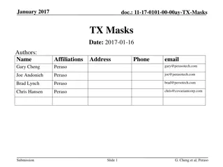
September 2017 doc.: IEEE 802.11-17/1423r1 Polarization in IEEE 802.11ay Date: 2017-09-08 Name Affiliations Address Phone email +7 (831) 2969444 Turgeneva 30, Nizhny Novgorod, 603024, Russia alexander.maltsev@intel.com Alexander Maltsev Intel andrey.pudeyev@intel.com Andrey Pudeyev Intel james.wang@mediatek.com James Wang Mediatek Submission Slide 1 Andrey Pudeyev, Intel
September 2017 doc.: IEEE 802.11-17/1423r1 Introduction Polarization effects have great impact on the millimeter wave propagation and may be used to improve the 11ay system performance However, there is still a question how to exploit and describe polarization effects in the IEEE 802.11ay: explicit introduction of polarization in information elements, properties and feedback, or without it. To answer that questions we will overview polarization antenna techniques and spatial processing algorithms which may be used to improve system performance Submission Slide 2 Andrey Pudeyev, Intel
September 2017 doc.: IEEE 802.11-17/1423r1 Phased antenna arrays with respect to polarization properties Type I: single polarization array with single RF chain Basic configuration, array with same polarization (horizontal, vertical, left/right circular) Type II: dual polarization array with two RF chains May be treated as two independent Type I antenna arrays with orthogonal polarization, combined at the same point of space Can be used both for polarization synthesis/polarization alignment and polarization-based STBC Type III: dual polarization array with single RF chain Can realize polarization synthesis/alignment at the TX/RX sides Require special antenna polarization control S S S Polarization synthesis control S S S S S S Beamforming Note: Modular antenna arrays (MAA) May be constructed from elementary arrays (types I,II,III) and treated as number of independent arrays S Submission Slide 3 Andrey Pudeyev, Intel
September 2017 doc.: IEEE 802.11-17/1423r1 Standard impact As long as each antenna with fixed polarization has its own RF chain, the system may treat antenna polarization property as channel propagation property. Therefore, for type I and II antennas polarization properties do not needed to be introduced in standard explicitly Transmissions over different polarizations considered as transmission over spatial channels (spatial diversity may come from polarization or angular separation, without difference from system point of view). For type III antennas, with single RF chain and adjustable polarization, the polarization properties should be controlled by system and thus this procedure should be described in the standard. For polarization control in type III antenna we need to know polarization capabilities, we need to indicate which polarization is used to organize measurements and feedback Before the decision making, the potential gains of polarization alignment for type III antennas should be investigated and compared with other techniques Submission Slide 4 Andrey Pudeyev, Intel
September 2017 doc.: IEEE 802.11-17/1423r1 Type III antenna array in Std. Type III array with polarization adjustment and single RF part may be efficiently used for polarization alignment of the TX polarization to fit RX one , and vice-versa. Implementation of polarization alignment procedure requires changes/additions to the 802.11ay spec However, type III array may be used in the Antenna Selection regime the array can be consequently set up to vertical, horizontal, or even some pre-defined rotated polarizations (for example 0 , 90 , 45 ) and the best options can be selected via standard antenna selection procedure Such usage of type III array may have some performance degradation in comparison with perfect (continuous) polarization alignment but with the minimal changes in the spec will be required (Antenna selection exists in 11d) Ant. #2 Ant. #3 Ant. #1 Ant. #4 Polarization synthesis control S S S S S S Beamforming S Antenna selection switch System/Spec point of view Implementation point of view Submission Slide 5 Andrey Pudeyev, Intel
September 2017 doc.: IEEE 802.11-17/1423r1 Polarization synthesis/alignment cases Polarization synthesis/ alignment can be done with Type III arrays (dual-polarized with single RF chain) Type II arrays (dual-polarized with two RF chains) Two type I arrays with orthogonal polarizations placed closely Dual polarized arrays can transmit at max power for all range of polarization angles Two orthogonal arrays cannot transmit at full (double) power for all polarization angles 13 dBm max 10 dBm V V 10 dBm H H Dual-polarized array, 10 dBm power Two single-polarized arrays, 10 dBm power each Submission Slide 6 Andrey Pudeyev, Intel
September 2017 doc.: IEEE 802.11-17/1423r1 Polarization alignment vs. STBC From the theoretical point of view, the polarization alignment and STBC scheme should have exactly the same performance: equivalent channel gain in both cases is equal to ???? + ?? Both schemes can be implemented on the base of dual- polarized arrays with two RF chains However, STBC implementation is preferable since in case of two arrays both can transmit at full power (see previous slide) TX antenna #2 2 2 RX antenna #1 H2 hvert Combiner H1 hhor Noise Submission Slide 7 Andrey Pudeyev, Intel
September 2017 doc.: IEEE 802.11-17/1423r1 Hotel Lobby scenario 2x1 system simulations Channel: 802.11ay model, Hotel lobby scenario (LOS / NLOS) TX: dual-polarized 2x8 antenna array 10 dBm power (total), ~17 dBi gain RX: single-polarization 2x8 array Uniform RX positions Fixed 45 elevation, (0 , 90 , 180 , 270 ) azimuth, random self-rotation Beamforming procedure: Enhanced-SLS based: TX-RX sector scan and best sector pair selection 33 sectors per array, ([-75 :15 :75 ] elevation, [-45 ,0 ,45 ] azimuth) Baseband processing: SISO or Alamouti STBC Submission Slide 8 Andrey Pudeyev, Intel
September 2017 doc.: IEEE 802.11-17/1423r1 Polarization modes performance comparison Typical situation was considered in all simulations: polarization-capable AP and simple vertically polarized antenna at the STA For comparison purposes, different antenna arrays configurations at the AP were considered, but the total power is fixed to 10 dBm for all antenna configurations Single polarization (V-V, H-V, Circular-V) Simple implementation May give unpredictable loss in case of misalignment Stable 3dB degradation for Circular-Vertical case Polarization alignment method: H,V adjustment at the TX so the resulting signal polarization at the RX will coincide with RX antenna polarization Suitable for type III antennas Eliminate polarization rotation losses 2x1 STBC (Alamouti scheme) Robust transmission scheme, require two RF chains Antenna selection Best (in terms of signal power) antenna/polarization is selected Correspond to type III array usage in antenna selection mode RX TX Submission Slide 9 Andrey Pudeyev, Intel
September 2017 doc.: IEEE 802.11-17/1423r1 Performance of different polarization schemes Polarization alignment and STBC has the same performance, due to our assumptions of equal TX power Robust circular polarization has 3 dB degradation Antenna selection between H and V (implementable with type III without spec impact) has only ~1 dB degradation in comparison with optimal solutions. The selection between H, V and two 45 polarizations provide less than 0.5 dB loss. Submission Slide 10 Andrey Pudeyev, Intel
September 2017 doc.: IEEE 802.11-17/1423r1 Polarization modes: summary Basic antenna array solution with single fixed polarization per RF chain does not require spec changes. Phased antenna array with adjustable polarization and single RF chain does require spec changes for implementation of the optimal polarization alignment scheme: polarization capabilities fields, feedback, etc. But this configuration in Antenna Selection mode (selection between pre- defined polarizations) with less than 0.5-1dB degradation in comparison with optimal alignment without changes to the spec. Dual-polarized antenna array with two RF chains may be used for Alamouti-STBC mode transmission, which have same performance as optimal polarization alignment, and also does not require additional polarization description in the Spec. Two arrays with orthogonal polarizations should be used for STBC rather than polarization alignment, due to more efficient total TX power usage. Submission Slide 11 Andrey Pudeyev, Intel
September 2017 doc.: IEEE 802.11-17/1423r1 Polarization and Beamforming In the simulations full TX sector sweep were performed for each antenna polarization and the best TX/RX sector selected. For considered case of several (Ntx) polarization at the TX and single (vertical) polarization at the RX that means that SLS is repeated for each polarization/antenna: Ntx times In case of several polarizations at the TX and RX, theoretically the number of sweeps should be Ntx * Nrx In practice, however, the squared overhead increase can be avoided: For Type I and II array at the RX, with number RF chains equal to the number of antenna polarizations, the receive polarization training can be performed simultaneously at the RX For Type III array at the RX in the polarization selection mode (slide 5), training of different antenna polarizations can be done in consecutive BTIs, if there is not enough TRN-R units in current BTI In addition, implementation-specific procedures may be used to reduce overhead on the base of polarization-beamforming relations. Submission Slide 12 Andrey Pudeyev, Intel
September 2017 doc.: IEEE 802.11-17/1423r1 Impact of polarization on beamforming study To evaluate impact of polarization effects on the beamforming results, simulation assumptions as in slide #9 were used 802.11ay model, Hotel lobby scenario (LOS / NLOS), 2x8 PAAs, Full sector level sweep beamforming 33 pre-defined sectors: [-75 :15 :75 ] elevation, [-45 ,0 ,45 ] azimuth Random RX orientation (azimuth and self-rotation) Vertical and horizontal at the TX, vertical at the RX Beamforming polarization degradation evaluated Best sector is selected for V-V and H-V transmission for each STA position and orientation The received power for V-V transmission evaluated for two cases: Beamforming were based on V-V sector sweep (best sector) Beamforming were based on H-V sector sweep (best sector for H-V transmission) So, the impact of polarization on the BF results were estimated Submission Slide 13 Andrey Pudeyev, Intel
September 2017 doc.: IEEE 802.11-17/1423r1 Impact of polarization on beamforming results It can be seen that for LOS (basic scenario), the beamforming can be performed for any polarization, the resulting signal power will be almost the same, except very low SNR range For NLOS scenario, (where reflection power depends on polarization) the mismatch of TX polarization during BF phase and TX polarization during transmission phase lead to 2-3 dB performance degradation Submission Slide 14 Andrey Pudeyev, Intel
September 2017 doc.: IEEE 802.11-17/1423r1 Beamforming and polarization: summary For baseline case when number of RF chains equal to number of antenna polarizations, the RX may receive the TRN-R training for all polarizations simultaneously, and evaluate the best RX sector for all polarizations in one BTI. For type III arrays with single RF and several possible polarizations, RX may perform SLS for different polarizations in the several BTIs (without overhead on system level) The result of SLS (selected sector and resulting signal strength) for LOS case is almost same for all polarizations, even for the Hotel Lobby scenario, with many reflections involved. For NLOS case, performing SLS on one polarization and usage for another one may lead to 2-3 dB degradation So, the BF results are robust enough for any combination of polarizations and thus, the AP may use only one preferred polarization for beamforming, with following polarization selection (great overhead reduction) Slide 15 Submission Andrey Pudeyev, Intel
September 2017 doc.: IEEE 802.11-17/1423r1 Conclusions Dual polarized antenna arrays may be used in the Standard without explicit polarization description Dual-pol, two RF chains - can be considered as two antennas and used for STBC, with same performance as ideal polarization synthesis/alignment Dual-pol, single RF can be considered as several antennas for Antenna Selection, with less than 0.5-1 dB degradation in comparison with ideal alignment. So, the number of RF chains always less or equal to the number of antennas 802.11ad: NRF=1, NAnt used for antenna selection 802.11ay base NAnt=NRF 802.11ay special case of several dual-polarized antennas: Nant NRF The sector scan and channel measurements should be performed per antennas, and result depends on the antenna, not the RF chain. Nantis always larger of equal NRF, DMG antenna unambiguously define RF chain used for TX/RX (and not vice-versa) So we propose to simplify the situation an use DMG Antenna ID only Note, that RF chain ID appears only in current 11ay draft, the other .11 stds including .11ac do not have such field Slide 16 Submission Andrey Pudeyev, Intel
September 2017 doc.: IEEE 802.11-17/1423r1 SP Do you agree with proposal to: Change RF Chain ID wherever it appears (Short SSW field, for example) to DMG Antenna ID Make other needed corrections to the text, connected with this changes Submission Slide 17 Andrey Pudeyev, Intel
September 2017 doc.: IEEE 802.11-17/1423r1 Backup Submission Slide 18 Andrey Pudeyev, Intel
September 2017 doc.: IEEE 802.11-17/1423r1 Polarization shcemes comparison Hotel lobby, NLOS Submission Slide 19 Andrey Pudeyev, Intel
September 2017 doc.: IEEE 802.11-17/1423r1 Open area scenario simulations Channel: 802.11ay model, Open area scenario (LOS / NLOS) TX: dual-polarized 2x8 antenna array 10 dBm power (total), ~17 dBi gain RX: single-polarization 2x8 array Uniform RX positions within sector Fixed 45 elevation, (0 , 90 , 180 , 270 ) azimuth, random self-rotation Beamforming procedure: Enhanced-SLS based: TX-RX sector scan and best sector pair selection 33 sectors per array Baseband processing: SISO or Alamouti STBC Submission Slide 20 Andrey Pudeyev, Intel
September 2017 doc.: IEEE 802.11-17/1423r1 Simulation results Submission Slide 21 Andrey Pudeyev, Intel