Electromagnetic Waves in a Plasma Study
 undefined


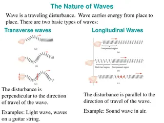
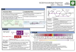
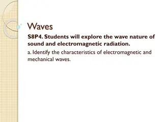
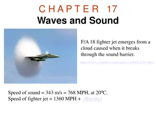
Electromagnetic waves
in a plasma
12
TH
NOVEMBER 2019
1
Simple models of dielectrics,
conductors and plasmas
•
Consider the motion of a bound electron in the presence of an applied electric field.
•
As the electron is separated from the positively charged nucleus due to electric field, an
electric dipole moment
is created.
•
The equation of motion for the dynamics of displacement x of the bound electron is
given as
•
Due to
•
The equation of motion becomes
2
3
https://ocw.mit.edu/courses/...and.../MIT6_007S11_lec22.pdf
Lorentz Dielectric Model
Externally applied E field
Simple models of dielectrics,
conductors and plasmas
•
Rewrite the equation of motion
•
The expression can be modified to suit each type of media; namely, dielectrics,
conductors and plasmas according to the following conditions.
4
Dielectrics : displacement
•
Let the applied electric field,
•
A possible solution of the equation of motion is given as
•
Substitute the displacement x(t) into the equation of motion, this gives
•
Therefore, and the corresponding velocity
•
Where the velocity of the electron is also in the sinusoidal form
5
Dielectric : effective permittivity
•
The
polarization per unit volume
P
is given by the product of
number of
dipole per unit volume
N
and the individual electric dipole moment
p
=
ex
•
The electric field displacement becomes
•
Where the
effective permittivity
(
) is
6
Electric susceptibility
Dielectrics : plasma frequency
p
and
susceptibility
(
)
•
The effective permittivity can be written in a more convenient form as follows
•
Where the
plasma frequency
is given as
•
The susceptibility is defined as
7
Dielectrics : effective permittivity
(
)
•
Recall the effective permittivity
•
Rewrite the value in the form of
8
Plots of real and imaginary parts of
the effective permittivity
•
The real and imaginary parts of
(
) characterize the refractive and absorptive
properties of the material.
9
Real part of the effective permittivity :
refractive index
•
Real dielectric materials exhibit several such resonant frequencies corresponding
to various vibrational modes and polarization mechanisms.
•
The permittivity becomes the sum of such terms:
•
Due to the
refractive index
,
the above relation can be
written in the following form known as the
Sellmeier equation
(where the
B
i
are
constants):
10
Sellmeier equation
•
In practice, the Sellmeier equation is applied in frequency ranges that are far from any
resonance so that one can effectively set
r
= 0:
•
Where
,
i
denote the corresponding free space wavelengths.
•
For example, the refractive indices of the fused silica (SiO
2
) over the range 0.2
3.7
m
can be accurately represented by the following Sellmeir equation (
in
m):
11
Conductors : conductivity
(
) (1)
•
Recall the current density
J
in terms of number of electron per unit volume
N
,
electric charge
e
and velocity
v
.
•
Therefore, the conductivity is given as
12
The expression of velocity v can
be found in slide #5.
Conductors : conductivity
(
) (2)
•
Considering
•
Therefore, is the
electric susceptibility
.
•
From
•
Since in a metal the conduction charge are unbound, let
0
= 0, we then obtain
13
Plasmas
•
To describe a collisionless plasma, such as ionosphere, the simple model in the
previous section can be used by choosing
0
=
r
= 0.
•
Thus, the conductivity in the previous section becomes pure imaginary :
•
The corresponding effective permittivity becomes purely real :
14
Refractive index of plasma (1)
•
In the expression for the refractive index
•
If
>
p
the electromagnetic wave propagates without attenuation within the
plasma. Refractive index
n
is
real
for all value of
and
so is the dielectric
constant
r
.
•
This can also be seen from the propagation number
k
•
The propagation wave number
k
is always real when
>
p
.
15
Refractive index of plasma (2)
•
Recall
•
For frequencies
>
p
the effective dielectric constant is less than unity
but the propagation constant is real.
Hence, the wave will be refracted by
the plasma according to the variation of
r
with altitude
.
•
Given that, in the ionosphere, the density of free electrons
N
10
12
m
-3
,
determine the plasma frequency?
•
The answer gives an intrinsic limit on the ability to do the radio astronomy from
the Earth’s surface.
.
16
Ionospheric structure
•
Radiation from the sun ionized the
earth’s atmosphere between about 90
to 1000 km above the earth’s surface.
•
Electrons are liberated from
molecules and a space of free
electrons and ions are created.
•
Free electron density on the order
of 10
10
to 10
12
electrons per cubic
meter
are produced by ionization
from the sun’s rays.
17
http://www.waves.utoronto.ca/prof/svhum/ece422/notes/20c-ionosphere.pdf
Electron density as a function of
altitude, and various ionospheric layers
The wave refraction in the ionosphere
•
When
>
p
, the wave gets refracted and the geometric optics, Snell’s law, can be applied.
•
Since the ionosphere is a plasma, it can be shown that the refractive index is less than unity.
Hence, the electromagnetic "ray" is bent away from the normal. This actually is
the total
reflection
.
•
The ionosphere may be subdivided into many layers.
•
The Snell’s law for the model is written as
18
Total internal reflection in the ionosphere
•
The condition for the wave to return to earth is to have
total internal reflection
, which
begin when the refracted angle is 90
0
. If this happens at the
k
th layer and
n
0
= 1,
•
This gives the minimum electron number density required to achieve the total internal
reflection as
•
This suggests that, apart from controlling the emitted power, the range of transmission
can be controlled by manipulating the angle of radiation.
19
Radio wave propagation
with ionospheric reflection
20
https://www.quora.com/How-far-do-longwave-radio-signals-travel
The major usefulness of the ionosphere is that the
reflections enable wave propagation over a much larger
distance than would be possible with line-of-sight.
Dispersion relation of plasma
•
From
•
This the dispersion relation of EM wave in
plasma as
•
At high frequencies (
>>
p
), the plasma
dispersion relation
approached the vacuum
relation
=ck
. Also, the effective dielectric
constant is 1.
•
What does this mean?
•
Practically, this happens at VHF frequencies
(30 – 300 MHz) and above.
21
http://web.mit.edu/8.334/www/grades/projects/projects08/EvangelosSfakianakis/9.htm
The group velocity of waves in the plasma
•
Regarding the dispersion relation of EM wave propagation in the plasma,
•
The group velocity
v
g
can be determined from d
/dk
•
The group velocity is less than c at all frequencies
>
p
.
22
What happens to the VHF waves
propagation in the ionosphere.
•
The wave simply pass through the
plasma
without significant
refraction.
•
However, there can be an effect from the
Earth’s magnetic field causing the
medium to become anisotropic.
•
Waves at these frequencies undergo
Faraday rotation by the ionosphere.
•
This means the polarization vector is
rotated as the wave passes through the
atmosphere.
23
http://www.waves.utoronto.ca/prof/svhum/ece422/notes/20c-ionosphere.pdf
What happens to the propagations of HW and SW?
Imaginary wave number
k
in plasma
•
Recall . When , the
wavenumber becomes imaginary
(j
).
•
In other words, the dielectric constant becomes negative and the propagation constant
becomes imaginary.
•
The electric filed of the wave
E
=
E
0
exp[j(
kz-
t
)] becomes
E
=
E
0
exp(-
z
)exp[j
t
]
•
The wave will
exponentially decay
with distance according to exp(-
z
).
•
The wave is NOT absorbed because the loss from electron collision has been ignored.
This implies that the wave incident on the medium surface would be totally reflected
.
•
The waves have a
cut off
at
=
p
.
24
<
p
Penetration depth in the plasma
•
When
<
p
, the wave number becomes imaginary. This suggests that the EM waves
incident on the plasma will be attenuated (
without absorption
) within the plasma.
•
The penetration depth can be worked out when the amplitude of the transmitted wave
becomes
1/
e
.
•
The penetration depth
= 1/
can be written as
•
This can be approximated as when
<<
p
.
25
The measurement of the electron
number density
•
The electromagnetic wave can
be used as probe to measure the
electron number density of
plasma.
•
The method relies on the
variation of the angular
frequency of the transmitted
wave until propagation no
longer occurs and a reflected
wave is reflected or vice versa.
26
Frequency dependence of the equivalent height of
reflection from the E and F regions of the ionosphere.
Determine the electron
number density at 100
km height.
The method of measuring the electron number density of the ionosphere
27
the dynamics of electromagnetic waves in plasma environments, including simple models for dielectrics, conductors, and plasmas. Discussing equations of motion for bound electrons, Lorentz dielectric model, and topics like effective permittivity, plasma frequency, and susceptibility.

Uploaded on Feb 16, 2025 | 0 Views
Download Presentation

Please find below an Image/Link to download the presentation.
The content on the website is provided AS IS for your information and personal use only. It may not be sold, licensed, or shared on other websites without obtaining consent from the author.If you encounter any issues during the download, it is possible that the publisher has removed the file from their server.
You are allowed to download the files provided on this website for personal or commercial use, subject to the condition that they are used lawfully. All files are the property of their respective owners.
The content on the website is provided AS IS for your information and personal use only. It may not be sold, licensed, or shared on other websites without obtaining consent from the author.
E N D
Presentation Transcript
Electromagnetic waves in a plasma 12THNOVEMBER 2019 1
Simple models of dielectrics, conductors and plasmas Consider the motion of a bound electron in the presence of an applied electric field. As the electron is separated from the positively charged nucleus due to electric field, an electric dipole moment is created. The equation of motion for the dynamics of displacement x of the bound electron is given as mx eE kx mrx = = x Due to k m 0 e m 2 0 + + = rx x E The equation of motion becomes 2
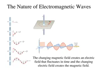
Lorentz Dielectric Model Externally applied E field https://ocw.mit.edu/courses/...and.../MIT6_007S11_lec22.pdf 3
Simple models of dielectrics, conductors and plasmas x e m 2 0 + + = rx x E Rewrite the equation of motion The expression can be modified to suit each type of media; namely, dielectrics, conductors and plasmas according to the following conditions. a. Dielectrics, a. Conductors, a. Collisionless Plasmas, 0, 0, = 0 r 0 0 r 0 = = 0, 0 r 0 4
Dielectrics : displacement ( ) Ee j t = E t Let the applied electric field, ( ) xe j t = x t A possible solution of the equation of motion is given as Substitute the displacement x(t) into the equation of motion, this gives 2 x j rx + eE m x j r + e m 2 0 + = x E e m j E = j x = = Therefore, and the corresponding velocity 2 2 0 v 2 2 0 + j r ( ) ve j t = v t Where the velocity of the electron is also in the sinusoidal form 5
Dielectric : effective permittivity The polarization per unit volume P is given by the product of number of dipole per unit volume N and the individual electric dipole moment p = ex Ne m P Np Nex 2 E = = = E 0 2 0 2 + j r ( ) ( ) ( ) = + = 01 + The electric field displacement becomes Where the effective permittivity ( ) is D E P E E 0 2 Ne m Electric susceptibility ( ) = + 0 2 0 2 + j r 6
Dielectrics : plasma frequency p and susceptibility ( ) The effective permittivity can be written in a more convenient form as follows 2 p + ( ) 0 = + 0 2 0 2 j r 2 Ne 2 p = Where the plasma frequency is given as m 0 2 p ( ) = The susceptibility is defined as 2 0 2 + j r 7
Dielectrics : effective permittivity ( ) 2 p + ( ) ( ) 0 = + Recall the effective permittivity 0 2 0 2 ( ) j r ( ) 2 0 2 ) ( ) 2 pr = j Rewrite the value in the form of 2 p 2 0 ( ) = + 0 ( 2 0 2 2 2 r + ( ) 0 = ( ) 2 2 0 2 2 2 r + 8
Plots of real and imaginary parts of the effective permittivity The real and imaginary parts of ( ) characterize the refractive and absorptive properties of the material. ( ) 2 pr 2 p 2 0 2 2 ( ) 0 0 = ( ) = + ( ) 2 0 ( ) 2 0 2 2 2 r + 2 0 2 2 2 r + 9
Real part of the effective permittivity : refractive index Real dielectric materials exhibit several such resonant frequencies corresponding to various vibrational modes and polarization mechanisms. 2 N e m + ( ) 0 The permittivity becomes the sum of such terms: i i i = + 0 0 2 i 2 j r i i ( ) n ( ) = Due to the refractive index written in the following form known as the Sellmeier equation (where the Bi are constants): ,the above relation can be 0 2 i i B ( ) 2 = + 1 n 0 2 i 2 + j r i i 10
Sellmeier equation In practice, the Sellmeier equation is applied in frequency ranges that are far from any resonance so that one can effectively set r = 0: 2 2 2 2 i i 2 i i B B ( ) i = + = + 1 1 n 2 2 i i Where , i denote the corresponding free space wavelengths. For example, the refractive indices of the fused silica (SiO2) over the range 0.2 3.7 m can be accurately represented by the following Sellmeir equation ( in m): 2 2 2 0.6961663 0.0684043 0.4079426 0.1162414 0.8974794 9.896161 2 + + + n ( ) ( ) ( ) 2 2 2 2 2 2 11
Conductors : conductivity ( ) (1) Recall the current density J in terms of number of electron per unit volume N, electric charge e and velocity v. 2 Ne j E m J Nev j r + ( ) The expression of velocity v can be found in slide #5. = = E 2 0 2 Therefore, the conductivity is given as 2 Ne m j 2 p j ( ) 0 2 = = 2 0 2 2 0 + j r + j r 12
Conductors : conductivity ( ) (2) Considering = = Nej x ( = = j P J Nev ) ( ) = P J j j E Therefore, is the electric susceptibility. ( ) ( ) j ( ) ( ) ( 0 1 = + ) ( ) ( ) ( ) = = j From 0 0 ( ) j 2 p + ( ) 0 = + = + 0 0 2 0 2 j r Since in a metal the conduction charge are unbound, let 0 = 0, we then obtain 2 0 2 j r + 2 p + j ( ) 0 p = = r j 13
Plasmas To describe a collisionless plasma, such as ionosphere, the simple model in the previous section can be used by choosing 0 = r = 0. Thus, the conductivity in the previous section becomes pure imaginary : 2 p ( ) 0 j = The corresponding effective permittivity becomes purely real : 1 2 2 p + 2 p ( ) ( ) 0 2 = + = = 1 ; plasma frequen cy = N e m 0 0 0 p 2 2 2 j r 0 14
Refractive index of plasma (1) ( ) In the expression for the refractive index ( ) 2 n 2 = = n r 0 2 p 81 f N = = = 1 1 r 2 2 0 If > p the electromagnetic wave propagates without attenuation within the plasma. Refractive index n is real for all value of and so is the dielectric constant r. This can also be seen from the propagation number k ( 0 0 p c ) 1 ( ) 2 2 2 2 p = = = = 1 k c k 0 r r The propagation wave number k is always real when > p . 15
Refractive index of plasma (2) ( ) ( 2 p 81 f N 2 Recall = = = 1 1 n r 2 2 0 ) 1 c ( ) 2 p 2 2 2 p = = = = 1 k c k 0 0 0 r r For frequencies > p the effective dielectric constant is less than unity but the propagation constant is real. Hence, the wave will be refracted by the plasma according to the variation of r with altitude. Given that, in the ionosphere, the density of free electrons N 1012 m-3, determine the plasma frequency? The answer gives an intrinsic limit on the ability to do the radio astronomy from the Earth s surface.. 16
Ionospheric structure Radiation from the sun ionized the earth s atmosphere between about 90 to 1000 km above the earth s surface. Electrons are liberated from molecules and a space of free electrons and ions are created. Free electron density on the order of 1010 to 1012 electrons per cubic meter are produced by ionization from the sun s rays. Electron density as a function of altitude, and various ionospheric layers http://www.waves.utoronto.ca/prof/svhum/ece422/notes/20c-ionosphere.pdf 17
The wave refraction in the ionosphere When > p , the wave gets refracted and the geometric optics, Snell s law, can be applied. Since the ionosphere is a plasma, it can be shown that the refractive index is less than unity. Hence, the electromagnetic "ray" is bent away from the normal. This actually is the total reflection. The ionosphere may be subdivided into many layers. The Snell s law for the model is written as = = = sin sin sin n n n 0 1 1 i k k 18
Total internal reflection in the ionosphere The condition for the wave to return to earth is to have total internal reflection, which begin when the refracted angle is 900. If this happens at the kth layer and n0 = 1, 0 = = sin sin90 n n i k = k 2 2 k = sin n . i r k This gives the minimum electron number density required to achieve the total internal reflection as 2 . sin 1 r k i = = 81 N f min 2 This suggests that, apart from controlling the emitted power, the range of transmission can be controlled by manipulating the angle of radiation. 19
Radio wave propagation with ionospheric reflection The major usefulness of the ionosphere is that the reflections enable wave propagation over a much larger distance than would be possible with line-of-sight. https://www.quora.com/How-far-do-longwave-radio-signals-travel 20
Dispersion relation of plasma From ( ) 1 c 2 p 2 2 2 p = = 1 k 0 o This the dispersion relation of EM wave in plasma as 2 2 2 k c = 2 p + At high frequencies ( >> p ), the plasma dispersion relation approached the vacuum relation =ck. Also, the effective dielectric constant is 1. What does this mean? Practically, this happens at VHF frequencies (30 300 MHz) and above. http://web.mit.edu/8.334/www/grades/projects/projects08/EvangelosSfakianakis/9.htm 21
The group velocity of waves in the plasma Regarding the dispersion relation of EM wave propagation in the plasma, 2 2 2 k c 2 p = + The group velocity vg can be determined from d /dk d dk 2 = 2 2 kc 2 p d dk k n c 2 2 = = = = 1 v c c c g 2 The group velocity is less than c at all frequencies > p . 22
What happens to the VHF waves propagation in the ionosphere. The wave simply pass through the plasma without significant refraction. However, there can be an effect from the Earth s magnetic field causing the medium to become anisotropic. Waves at these frequencies undergo Faraday rotation by the ionosphere. This means the polarization vector is rotated as the wave passes through the atmosphere. What happens to the propagations of HW and SW? http://www.waves.utoronto.ca/prof/svhum/ece422/notes/20c-ionosphere.pdf 23
Imaginary wave number k in plasma 1 2 2 Recall . When , the wavenumber becomes imaginary (j ). p k c = < p In other words, the dielectric constant becomes negative and the propagation constant becomes imaginary. The electric filed of the wave E=E0exp[j(kz- t)] becomes E=E0exp(- z)exp[j t] The wave will exponentially decay with distance according to exp(- z). The wave is NOT absorbed because the loss from electron collision has been ignored. This implies that the wave incident on the medium surface would be totally reflected. The waves have a cut off at = p . 24
Penetration depth in the plasma When < p, the wave number becomes imaginary. This suggests that the EM waves incident on the plasma will be attenuated (without absorption) within the plasma. The penetration depth can be worked out when the amplitude of the transmitted wave becomes 1/e. The penetration depth = 1/ can be written as 1 2 2 1 c = = 1 2 p p This can be approximated as when << p . c p 25
The measurement of the electron number density The electromagnetic wave can be used as probe to measure the electron number density of plasma. Determine the electron number density at 100 km height. The method relies on the variation of the angular frequency of the transmitted wave until propagation no longer occurs and a reflected wave is reflected or vice versa. Frequency dependence of the equivalent height of reflection from the E and F regions of the ionosphere. 26
The method of measuring the electron number density of the ionosphere 1 2 2 Ne m = p 0 e 27


")


 (1)")
 (2)")

")
")