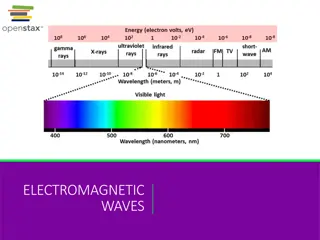
Electromagnetic Testing (ET) in NDT

Electromagnetic Testing (ET)

Electromagnetic Testing (ET)
Electromagnetic Testing
Electromagnetic testing is a general test category that includes
Eddy Current testing (ECT), Alternating Current Field
Measurement (ACFM) and Remote Field testing. All of these
techniques use the induction of an electric current or magnetic
field into a conductive part, then the resulting effects are
recorded and evaluated.
Definition
•
An NDT method that uses the principal of electromagnetism
as the basis for conducting examinations
Electromagnetic Testing (ET)
Uses for ET
•
Crack detection
•
Material thickness measurement
•
Coating thickness measurement
•
Conductivity measurements
–
For material identification, heat damage detection, heat treatment
monitoring
•
Used by the airline industry for inspection of aircraft skins
(surface testing)
•
Used by the nuclear power industry for inspection of heat
exchanger tubing (volumetric testing)
•
Electromagnetic Testing (ET)
Advantages of ET as an NDT method
•
Sensitive to small cracks/defects
•
Good for inspection of surface/near-surface defects (unlike
UT)
•
Immediate results
•
Portable
•
Minimal part preparation
•
Can inspect complex shapes and sizes of conductive materials
Electromagnetic Testing (ET)
Limitations of ET as an NDT method
•
Only good on conductive materials (not on magnetic
materials)
•
Extensive skill and training required for interpretation of
results
•
Surface finish or build-up may interfere with test results
•
Need reference standards for set-up
•
Limited depth of penetration
Electromagnetic Testing (ET)
History
•
1831 - Michael Faraday discovered electromagnetic induction
•
1879 – Hughes recorded changes in the properties of a coil
when placed in contact with metals of different conductivity
and permeability
•
World War II – eddy current testing first put to practical use
for testing of materials
Electromagnetic Induction
•
Eddy currents are created through the process of
electromagnetic induction
–
Eddy currents - induced electrical currents that flow in a
circular path
Electromagnetic Testing (ET)
Current Research
•
Photo inductive Imaging (PI) – way to image local stress
variations in steel
•
Pulsed Eddy Current – used for detection and quantification of
corrosion and cracking in multi-layer aluminum aircraft
structures – better depth penetration – can be applied to
ferromagnetic materials
Properties of Electricity – Electrical Current
•
Electrical current is the flow of electrons
•
Current is measured in amperes or amps (I)
•
1 Amp = 1 Coulomb (measure of charge) per 1 second
Electromagnetic Testing (ET)
Electromotive Force
•
EMF is the force that causes electrons to move
•
Measured in Volts (V)
•
Sources of EMF include batteries and electric generators
Power and Energy
•
Power expressed in Watts
•
Energy expressed in Joules
•
1 Joule = 1 Watt – second
–
Amount of energy consumed when one Watt of power
acts for one second
Electromagnetic Testing (ET)
Resistance
•
Resistance (R) - opposition of a substance to the flow of
current
–
Depends on the type of material
–
Measured in Ohms (
Ω
)
–
Materials with high resistance are good insulators;
materials with low resistance are good conductors (copper,
gold)
Electromagnetic Testing (ET)
Ohm’s Law
•
I = V/R
–
In words: current = voltage / resistance
•
An increase in voltage or a decrease in resistance will result in
an increase in current
•
A decrease in voltage or an increase in resistance will result in
a decrease in current
Induction
•
Current passing through a coil generates a magnetic field
•
A moving magnetic field induces a current in an electrically
conductive material (only present in AC circuits)
Electromagnetic Testing (ET)
Diagram of Induction
Electromagnetic Testing (ET)
Inductance/Inductive Reactance
•
Inductance (L) – when induction occurs in an electrical circuit
and affects the flow of electricity
•
Inductive Reactance – reduction of current flow in a circuit
due to induction
Electromagnetic Testing (ET)
Eddy Current Inspection
•
Coil used to generate primary magnetic field in a conductive
material
•
This magnetic field induces eddy currents in the material
•
These eddy currents subsequently produce a secondary
magnetic field which interacts with the primary magnetic field
Electromagnetic Testing (ET)
Eddy Current Inspection
•
By measuring the change in resistance and inductive
reactance of the coil can determine information about the
material
–
Electrical conductivity
–
Magnetic permeability
–
Material thickness
–
Condition of material (defect-free?)
Electromagnetic Testing (ET)
Liftoff
•
Distance between coil and conductive material
•
Used to make measurements of thickness of nonconductive
coatings
Phase Angle
•
In inductive/resistive circuits, voltage leads current by 90
o
–
Voltage across the inductor is maximized when the current
= 0
•
When inductance is present (not just resistance), voltage and
current are out of phase
Electromagnetic Testing (ET)
More About Eddy Currents
•
Closed loops of induced current circulating in planes
perpendicular to magnetic flux
•
Travel parallel to coil’s winding
•
Concentrate near surface
•
Strength decreases with distance from coil (skin effect)
Depth of Penetration
•
Affected by frequency of excitation current, electrical
conductivity, and permeability of specimen
•
Decreases with an increase in frequency, conductivity, or
magnetic permeability
Electromagnetic Testing (ET)
Standard Depth of Penetration (δ)
•
Eddy current field intensity greatest at surface and decreases
exponentially with depth
•
Depth at which eddy current density has decreased to 37% of
surface value referred to as the standard depth of
penetration,
δ
•
Test frequency often selected to place suspected flaw within
one δ
Electromagnetic Testing (ET)
Eddy Current Depth of Penetration (δ)
Electromagnetic Testing (ET)
Frequency for Conductivity Measurement
•
If test intended to determine a material’s conductivity, the
frequency is set to about 3δ
•
By the time the signal gets to the other side of the material, it
is very weak
Phase Lag
•
Both voltage and current will have a phase lag (shift in time)
with depth
•
It is possible to approximate the depth of a defect based on
the phase lag
•
Depth of Flaw ≈ Phase Lag * Standard Depth of Penetration
•
Note: this is different than
phase angle
(shift between current
and voltage)
Electromagnetic Testing (ET)
Evaluation of Eddy Current Signal
•
Signal produced by a flaw depends on both amplitude and
phase lag of eddy currents being disrupted
•
A small surface defect and a large internal defect can have the
same magnitude at 1δ, but will have a phase lag of ~57
o
Conductivity
•
Conductivity of metals is measured in MS/m (mega Siemens
per meter)
•
A Siemen is the inverse of an Ohm (1S = 1/1Ω)
•
Conductivities of metals range from 1-60 MS/m.
Electromagnetic Testing (ET)
Conductivity (continued)
•
Conductivity is often expressed as a percentage of the
conductivity of a standard sample of copper
•
International Annealed Copper Standard (IACS) established in
1913 (100% IACS = 58 MS/m (pure copper))
•
Today pure copper has a conductivity that exceeds 100% IACS
Conductivity Measurement
•
For example a GE Phasec 3S used for surface inspections and
conductivity measurements Measures conductivity in the
range of 0.8 – 110% IACS
•
Conductivity of various materials
–
Aluminum ~35% IACS
–
Titanium ~ 1% IACS
Electromagnetic Testing (ET) is a crucial NDT method involving techniques like Eddy Current Testing (ECT) and Alternating Current Field Measurement (ACFM). It is used for crack detection, material thickness measurement, and more in various industries due to its sensitivity and immediate results. Despite its advantages such as being portable and applicable to complex shapes, ET has limitations like requiring extensive skills and being limited to conductive materials. The history of ET dates back to Michael Faraday's discovery of electromagnetic induction in 1831.

Download Presentation

Please find below an Image/Link to download the presentation.
The content on the website is provided AS IS for your information and personal use only. It may not be sold, licensed, or shared on other websites without obtaining consent from the author.If you encounter any issues during the download, it is possible that the publisher has removed the file from their server.
You are allowed to download the files provided on this website for personal or commercial use, subject to the condition that they are used lawfully. All files are the property of their respective owners.
The content on the website is provided AS IS for your information and personal use only. It may not be sold, licensed, or shared on other websites without obtaining consent from the author.
E N D
Presentation Transcript
Electromagnetic Testing (ET) Electromagnetic Testing Electromagnetic testing is a general test category that includes Eddy Current testing (ECT), Alternating Current Field Measurement (ACFM) and Remote Field testing. All of these techniques use the induction of an electric current or magnetic field into a conductive part, then the resulting effects are recorded and evaluated. Definition An NDT method that uses the principal of electromagnetism as the basis for conducting examinations
Electromagnetic Testing (ET) Uses for ET Crack detection Material thickness measurement Coating thickness measurement Conductivity measurements For material identification, heat damage detection, heat treatment monitoring Used by the airline industry for inspection of aircraft skins (surface testing) Used by the nuclear power industry for inspection of heat exchanger tubing (volumetric testing)
Electromagnetic Testing (ET) Advantages of ET as an NDT method Sensitive to small cracks/defects Good for inspection of surface/near-surface defects (unlike UT) Immediate results Portable Minimal part preparation Can inspect complex shapes and sizes of conductive materials
Electromagnetic Testing (ET) Limitations of ET as an NDT method Only good on conductive materials (not on magnetic materials) Extensive skill and training required for interpretation of results Surface finish or build-up may interfere with test results Need reference standards for set-up Limited depth of penetration
Electromagnetic Testing (ET) History 1831 - Michael Faraday discovered electromagnetic induction 1879 Hughes recorded changes in the properties of a coil when placed in contact with metals of different conductivity and permeability World War II eddy current testing first put to practical use for testing of materials Electromagnetic Induction Eddy currents are created through the process of electromagnetic induction Eddy currents - induced electrical currents that flow in a circular path
Electromagnetic Testing (ET) Current Research Photo inductive Imaging (PI) way to image local stress variations in steel Pulsed Eddy Current used for detection and quantification of corrosion and cracking in multi-layer aluminum aircraft structures better depth penetration can be applied to ferromagnetic materials Properties of Electricity Electrical Current Electrical current is the flow of electrons Current is measured in amperes or amps (I) 1 Amp = 1 Coulomb (measure of charge) per 1 second
Electromagnetic Testing (ET) Electromotive Force EMF is the force that causes electrons to move Measured in Volts (V) Sources of EMF include batteries and electric generators Power and Energy Power expressed in Watts Energy expressed in Joules 1 Joule = 1 Watt second Amount of energy consumed when one Watt of power acts for one second
Electromagnetic Testing (ET) Resistance Resistance (R) - opposition of a substance to the flow of current Depends on the type of material Measured in Ohms ( ) Materials with high resistance are good insulators; materials with low resistance are good conductors (copper, gold)
Electromagnetic Testing (ET) Ohm s Law I = V/R In words: current = voltage / resistance An increase in voltage or a decrease in resistance will result in an increase in current A decrease in voltage or an increase in resistance will result in a decrease in current Induction Current passing through a coil generates a magnetic field A moving magnetic field induces a current in an electrically conductive material (only present in AC circuits)
Electromagnetic Testing (ET) Diagram of Induction
Electromagnetic Testing (ET) Inductance/Inductive Reactance Inductance (L) when induction occurs in an electrical circuit and affects the flow of electricity Inductive Reactance reduction of current flow in a circuit due to induction
Electromagnetic Testing (ET) Eddy Current Inspection Coil used to generate primary magnetic field in a conductive material This magnetic field induces eddy currents in the material These eddy currents subsequently produce a secondary magnetic field which interacts with the primary magnetic field
Electromagnetic Testing (ET) Eddy Current Inspection By measuring the change in resistance and inductive reactance of the coil can determine information about the material Electrical conductivity Magnetic permeability Material thickness Condition of material (defect-free?)
Electromagnetic Testing (ET) Liftoff Distance between coil and conductive material Used to make measurements of thickness of nonconductive coatings Phase Angle In inductive/resistive circuits, voltage leads current by 90o Voltage across the inductor is maximized when the current = 0 When inductance is present (not just resistance), voltage and current are out of phase
Electromagnetic Testing (ET) More About Eddy Currents Closed loops of induced current circulating in planes perpendicular to magnetic flux Travel parallel to coil s winding Concentrate near surface Strength decreases with distance from coil (skin effect) Depth of Penetration Affected by frequency of excitation current, electrical conductivity, and permeability of specimen Decreases with an increase in frequency, conductivity, or magnetic permeability
Electromagnetic Testing (ET) Standard Depth of Penetration ( ) Eddy current field intensity greatest at surface and decreases exponentially with depth Depth at which eddy current density has decreased to 37% of surface value referred to as the standard depth of penetration, Test frequency often selected to place suspected flaw within one
Electromagnetic Testing (ET) Eddy Current Depth of Penetration ( )
Electromagnetic Testing (ET) Frequency for Conductivity Measurement If test intended to determine a material s conductivity, the frequency is set to about 3 By the time the signal gets to the other side of the material, it is very weak Phase Lag Both voltage and current will have a phase lag (shift in time) with depth It is possible to approximate the depth of a defect based on the phase lag Depth of Flaw Phase Lag * Standard Depth of Penetration Note: this is different than phase angle (shift between current and voltage)
Electromagnetic Testing (ET) Evaluation of Eddy Current Signal Signal produced by a flaw depends on both amplitude and phase lag of eddy currents being disrupted A small surface defect and a large internal defect can have the same magnitude at 1 , but will have a phase lag of ~57o Conductivity Conductivity of metals is measured in MS/m (mega Siemens per meter) A Siemen is the inverse of an Ohm (1S = 1/1 ) Conductivities of metals range from 1-60 MS/m.
Electromagnetic Testing (ET) Conductivity (continued) Conductivity is often expressed as a percentage of the conductivity of a standard sample of copper International Annealed Copper Standard (IACS) established in 1913 (100% IACS = 58 MS/m (pure copper)) Today pure copper has a conductivity that exceeds 100% IACS Conductivity Measurement For example a GE Phasec 3S used for surface inspections and conductivity measurements Measures conductivity in the range of 0.8 110% IACS Conductivity of various materials Aluminum ~35% IACS Titanium ~ 1% IACS
")
")
")
")
")
")
")
")
")
")
")
")
")
")
")
")
")
")
")
")
")