Electrical Controls Presentation for AAVIM Lessons
Explore the comprehensive PowerPoint presentation developed by Sidney Bell to accompany Dr. James Allison's Electrical Controls textbook. Dive into control circuit ladder diagrams, push button stations, limit switches, motor contactors, relays, and more for single-phase motor control applications.

Download Presentation

Please find below an Image/Link to download the presentation.
The content on the website is provided AS IS for your information and personal use only. It may not be sold, licensed, or shared on other websites without obtaining consent from the author. If you encounter any issues during the download, it is possible that the publisher has removed the file from their server.
You are allowed to download the files provided on this website for personal or commercial use, subject to the condition that they are used lawfully. All files are the property of their respective owners.
The content on the website is provided AS IS for your information and personal use only. It may not be sold, licensed, or shared on other websites without obtaining consent from the author.
E N D
Presentation Transcript
Electrical Controls PowerPoint to Accompany Lessons in AAVIM, Electrical Controls Textbook by Dr. James Allison PowerPoint Developed by Sidney Bell
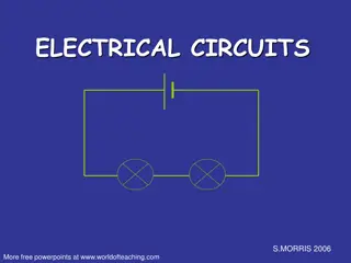
Control Circuit Ladder Diagram C L 1 N 240 V single phase motor for a feed bin auger, controlled by a push button station, normally open limit switch and normally open motor relay
Normally Open Limit Switch (N.O.) Door closed Door open Limit switch Limit switch
Push Button Station Normally Open START Normally Closed STOP
Normally Open Auxiliary Contacts
Motor Contactor C 120 V Coil
DPST NO Relay (Contactor) L2 L1 Coil T2 T1 Auxiliary Contact M
N L2 L1 T1 T2 M
N L2 L1 T1 T2 M
L2 L1 3 1 X1 X2 2 T2 T1 DPST - NO Magnetic Starter 240V Coil (Relay with an overload sensing component) NEC 430.84 & 430.105
L1 L2 M1 M1 M2 TD THERMAL TIME DELAY Ladder diagram of hammer mill and auger control circuit
L1 L2 L2 L2 1 1 TD THERMAL TIME DELAY MOTOR 2 MOTOR 1
L1 L2 L2 L2 1 1 TD THERMAL TIME DELAY MOTOR 2 MOTOR 1 Auger Hammer mill
Two 240 V Lamps Controlled by Mechanical Timers N L2 L1 T1 Mechanical Timers T2 Lamps 240 V


")