Doppler Mitigation for High-speed Rail Communications
In this July 2016 submission to IEEE P802.15 Working Group for Wireless Personal Area Networks, Doppler Mitigation for High-speed Rail Communications is discussed. The document explores problems of OFDM-based systems for HSR communications, conventional Doppler compensation methods, and the need for Doppler mitigation strategies due to the severe Doppler effect in high-speed rail environments. Various slides in the submission cover topics such as bidirectional network deployment, channel models, and discussions on Doppler mitigation techniques. The contribution by Bing Hui and ETRI addresses vital technologies for overcoming challenges in high-speed rail communications, focusing on handling Doppler frequency spread and interference issues.

Download Presentation

Please find below an Image/Link to download the presentation.
The content on the website is provided AS IS for your information and personal use only. It may not be sold, licensed, or shared on other websites without obtaining consent from the author. If you encounter any issues during the download, it is possible that the publisher has removed the file from their server.
You are allowed to download the files provided on this website for personal or commercial use, subject to the condition that they are used lawfully. All files are the property of their respective owners.
The content on the website is provided AS IS for your information and personal use only. It may not be sold, licensed, or shared on other websites without obtaining consent from the author.
E N D
Presentation Transcript
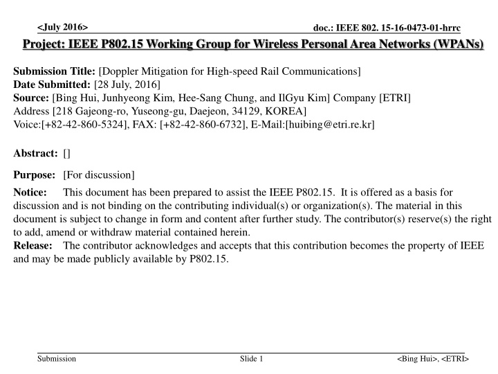
<July 2016> doc.: IEEE 802. 15-16-0473-01-hrrc Project: IEEE P802.15 Working Group for Wireless Personal Area Networks (WPANs) Submission Title: [Doppler Mitigation for High-speed Rail Communications] Date Submitted: [28 July, 2016] Source: [Bing Hui, Junhyeong Kim, Hee-Sang Chung, and IlGyu Kim] Company [ETRI] Address [218 Gajeong-ro, Yuseong-gu, Daejeon, 34129, KOREA] Voice:[+82-42-860-5324], FAX: [+82-42-860-6732], E-Mail:[huibing@etri.re.kr] Abstract: [] Purpose: [For discussion] Notice: This document has been prepared to assist the IEEE P802.15. It is offered as a basis for discussion and is not binding on the contributing individual(s) or organization(s). The material in this document is subject to change in form and content after further study. The contributor(s) reserve(s) the right to add, amend or withdraw material contained herein. Release: The contributor acknowledges and accepts that this contribution becomes the property of IEEE and may be made publicly available by P802.15. Submission Slide 1 <Bing Hui>, <ETRI>
<July 2016> doc.: IEEE 802. 15-16-0473-01-hrrc Doppler Mitigation for High-speed Rail Communications Submission Slide 2 <Bing Hui>, <ETRI>
<July 2016> doc.: IEEE 802. 15-16-0473-01-hrrc Outline Background Bidirectional Network Deployment Channel Model Doppler Mitigation for HSR Communications Discussions Submission Slide 3 <Bing Hui>, <ETRI>
<July 2016> doc.: IEEE 802. 15-16-0473-01-hrrc Background Problems of OFDM based Systems for HSR Communications OFDM is sensitive to ICI Restraining Inter-Carrier Interference (ICI), estimating and compensating frequency shift are vital technologies. mmWave introduces much high Doppler shift Doubled Doppler Spread in TDD UL UE estimates the DL carrier frequency and use it as the central frequency for UL transmission. The Doppler frequency spread and the oscillator frequency offset cannot be distinguished by UE. The Doppler spread in DL will be accumulated in the UL reception. Therefore, totally doubled Doppler frequency spread will be received by UL receiver. Submission Slide 4 <Bing Hui>, <ETRI>
<July 2016> doc.: IEEE 802. 15-16-0473-01-hrrc Background Conventional Doppler Compensation Method AOA & velocity estimation based Doppler compensation Multi-tap in time-domain & complex Not accurate & not suitable for OFDM Correlation based methods Computationally high Need a significant load of measurements Not suitable for HSR communications Channel varies fast Doppler effect is severe. Submission Slide 5 <Bing Hui>, <ETRI>
<July 2016> doc.: IEEE 802. 15-16-0473-01-hrrc Bidirectional Network Deployment Mobile Hotspot Network (MHN) System Architecture Mobile wireless backhaul supporting very high traffic volume on new frontier bands (mmWave) Backhaul link : use mmWave Access link inside vehicle : use sub 6GHz (Wi-Fi or Small cell) Inter-mDU Public Core Network Mobility Controller mGW mGW: MHN Gateway mDU: MHN Digital Unit mRU: MHN Radio Unit mTE: MHN Terminal Equipment mDU mDU Intra-mDU Mobility Controller Access Link: WiFi (sub-6 GHz Inside Vehicle) Backhaul Link: mmWave mTE (31.5~31.75 GHz) mRU mRU mRU mRU 1 Km Distance Submission Slide 6 <Bing Hui>, <ETRI>
<July 2016> doc.: IEEE 802. 15-16-0473-01-hrrc Bidirectional Network Deployment Wireless Backhaul Connections DU (i+1) DU i . . . . . . . . . . . . RU (n+p) RU n RU (m+k) RU m RU (n+1) RU (m+1) . . . . . . . . . . . . . . . . . . . . . . . . Fig. DU-RUs connections RU (n+1) RU (n+1) RU n RU n Backward Link Tail Ant Head Ant Backward Link Forward Link Forward Link Ant Fig. Single TE antenna case Fig. Double TE antennas case Submission Slide 7 <Bing Hui>, <ETRI>
<July 2016> doc.: IEEE 802. 15-16-0473-01-hrrc Channel Model Multipath multi-tap channel (TDL model) ? (?,? = ?? ?? ??(? ?(? ?? ?=1 Weight for WSSUS model ?0 1 ?exp ?2???cos(?? ? ??(? = ?? ?0 ?=1 Simplified Channel w. Doppler (? = ?(? exp(?2???? V Doppler Shift ??=??0 cos? ? Submission Slide 8 <Bing Hui>, <ETRI>
<July 2016> doc.: IEEE 802. 15-16-0473-01-hrrc Doppler Mitigation Method Channel Behaviors of both Links Forward link ( ) ( ) t ( ) t = exp 2 h a j f t , fwd fwd d fwd Backward link ( ) bwd h t ( ) ( ) t = exp 2 bwd a j f t , d bwd Received Signals ( ) head y t ( ) t ( ) ( ) t = + h S t head n fwd ( ) t ( ) t ( ) ( ) t = + y bwd h S t n tail tail Submission Slide 9 <Bing Hui>, <ETRI>
<July 2016> doc.: IEEE 802. 15-16-0473-01-hrrc Doppler Mitigation Method Transmitted OFDM Symbols ?(? = ?(? exp(?2??0? Received Symbol ( ) ( ) ( ) ( ) t a ( ) t + = = , Y t y t y head h tail ( ) ( ) ( ) t ( ) t ( ) ( ) t ] [ + [ ], t S t head n bwd h S t n fwd tail = ( )exp( 4 t s t exp[ 2 ( ) ] ) a t j f f j f t , , fwd bwd d fwd d bwd C ( ( ) ) ( ) ( ) ( ) t n ( ) ( ) ( ) l i ( ) ( ) + f t n exp 2 h t s t j t Input y1(t) fwd C ta il + f t n exp 2 bwd h n t s t j t C head Output Y(t) HPF + . t h e ad ta Input y2(t) Fig. Block Diagram of the Receiver Submission Slide 10 <Bing Hui>, <ETRI>
<July 2016> doc.: IEEE 802. 15-16-0473-01-hrrc Doppler Mitigation Method System Parameters Parameter Setup Frequency 32 GHz Antenna Configuration 1 Head Ant. + 1 Tail Ant. / Single Ant. Antenna Height 6.5 m for RU, 3 m for TE Antenna Setup Directional Ant. / Omni-directional Ant. Length of Train Distance Speed 200 m 1 km 100 m/s (360 km/h) Submission Slide 11 <Bing Hui>, <ETRI>
<July 2016> doc.: IEEE 802. 15-16-0473-01-hrrc Doppler Mitigation Method Maximum Doppler Shift Performance Assume the fixed highest mobility Suitable for time-varying mobility and better performance can be achieved. 15 15 10 10 Head Ant. Combined Tail Ant. Head Ant. Combined Tail Ant. 5 5 Doppler Shift (kHz) Doppler Shift (kHz) 0 0 -5 -5 -10 -10 -15 -15 0 200 400 600 800 1000 1200 1400 1600 1800 2000 0 200 400 600 800 1000 1200 1400 1600 1800 2000 Location (m) Location (m) Fig. Residual Doppler shift after DL reception Fig. Residual Doppler shift before UL transmission Submission Slide 12 <Bing Hui>, <ETRI>
<July 2016> doc.: IEEE 802. 15-16-0473-01-hrrc Discussions Pros Efficiently remove Doppler effect for most of the cases without the necessity of estimating Doppler spread In most of the cases (90% in the shown example), the residual Doppler shift is 0 Hz. Time-domain pilot density can be reduced since the residual Doppler shift is 0 Hz with high probability. Even though the peaks of residual Doppler shift exist, the handover should be performed at the exact time of peak residual Doppler, therefore the influence of peak residual Doppler shift to the data transmission and reception is limited. Reduce residual Doppler shift Especially for UL, residual Doppler shift in DL can be reduced by half for UL transmission due to the doubled carrier frequency after multiplication of the two received signals (two antennas on the train) Robust to the time-varying mobility Since the head antenna and the tail antenna always have the same mobility with the opposite direction, the residual Doppler shift will be 0 Hz no matter how the mobility varies with the time. Complexity reduction of automatic frequency control (AFC) Since the frequency offset after implementing the invented Doppler mitigation method is dramatically reduced, an AFC with relatively low computational complexity may be enough to further compensate the remaining frequency offset. Cons 2 receive antennas are required. X2 interface is necessary among DUs for UL case. IF processing may be necessary. Submission Slide 13 <Bing Hui>, <ETRI>