Coordinated Spatial Reuse in IEEE 802.11bn Standard
This contribution explores Coordinated Spatial Reuse (Co-SR) as a potential multi-AP feature for the IEEE 802.11bn standard. It discusses the trade-offs, proposes a method for downlink channel access, and evaluates its impact on goodput and packet delivery delay. The background highlights the gains and losses associated with Co-SR, emphasizing reduced frame delivery delay and increased aggregate goodput through coordinated AP transmissions. The illustrations depict channel access by multiple APs, showcasing the benefits and challenges of Co-SR implementation.
Download Presentation

Please find below an Image/Link to download the presentation.
The content on the website is provided AS IS for your information and personal use only. It may not be sold, licensed, or shared on other websites without obtaining consent from the author.If you encounter any issues during the download, it is possible that the publisher has removed the file from their server.
You are allowed to download the files provided on this website for personal or commercial use, subject to the condition that they are used lawfully. All files are the property of their respective owners.
The content on the website is provided AS IS for your information and personal use only. It may not be sold, licensed, or shared on other websites without obtaining consent from the author.
E N D
Presentation Transcript
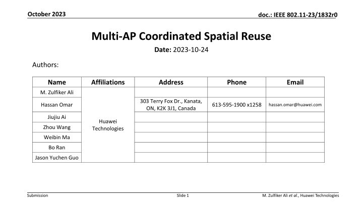
October 2023 doc.: IEEE 802.11-23/1832r0 Multi-AP Coordinated Spatial Reuse Date: 2023-10-24 Authors: Name Affiliations Address Phone Email M. Zulfiker Ali 303 Terry Fox Dr., Kanata, ON, K2K 3J1, Canada Hassan Omar 613-595-1900 x1258 hassan.omar@huawei.com Jiujiu Ai Huawei Technologies Zhou Wang Weibin Ma Bo Ran Jason Yuchen Guo Submission Slide 1 M. Zulfiker Ali et al., Huawei Technologies
October 2023 doc.: IEEE 802.11-23/1832r0 Abstract This contribution discusses coordinated spatial reuse (Co-SR) as a potential multi- AP feature for the IEEE 802.11bn standard. First, a trade-off that is associated with Co-SR is highlighted. Then, a general Co-SR method for downlink channel access is proposed and evaluated, in terms of aggregate goodput and average/worst-case packet delivery delay. Submission Slide 2 M. Zulfiker Ali et al., Huawei Technologies
October 2023 doc.: IEEE 802.11-23/1832r0 Background Coordinated spatial reuse (Co-SR) Potential gains 1) A reduction in frame delivery delay [mean or standard deviation (STD)], as a result of a decrease in the channel access delay for a coordinated AP (Co-AP) by exploiting the TXOPs shared by other Co-APs 2) An increase in aggregate goodput as a result of concurrent transmissions by CoAPs over the same frequency channel Transmit Time No TXOP sharing TXOP sharing using Co-SR power/modulation and coding index AP 1 AP 2 Potential losses Channel bandwidth Frequency 1) Transmission of control (overhead) frames for AP coordination 2) An increase in a physical layer protocol data unit (PPDU) transmission duration, due to PPDU transmission with a reduced data rate, as a result of a reduction in transmit power or modulation and coding scheme (MCS) index Illustration of channel access by two APs Start of channel access by an AP1 Start of channel contention by AP1 AP1 channel access delay Frequency AP1 back-off counter freezing Transmission by AP1 Transmission by AP2 Channel busy duration No Co-SR Tradeoff associated with Co-SR time AIFS and back-off counter decrement Arbitrary inter-frame spacing (AIFS) and back-off counter decrement Channel access delay Aggregate goodput Total frame delivery delay Start of channel access by an AP1 Start of channel contention by AP1 PPDU transmission duration Overhead for multi- AP coordination AP1 channel access delay Frequency Co-trigger frame Due to employment of a lower MCS index Transmission by AP2 Transmission by AP1 Channel busy duration Co-SR time AIFS and back-off counter decrement SIFS Submission Slide 3 M. Zulfiker Ali et al., Huawei Technologies
October 2023 doc.: IEEE 802.11-23/1832r0 Background OBSS PD-based SR in the IEEE 802.11ax standard Issue illustration Standard values Favorable SR scenario Non-favorable SR scenario STA1 STA2 STA2 STA1 AP1 AP2 AP1 AP2 Desired signal The OBSS PD-based SR does not differentiate between the two cases Interference signal Main issues Signal used for OBSS PD-based SR enablement Simultaneous OBSS PD-based SR enablement STA1 STA3 1) An STA determines whether or not to exploit OBSS PD-based SR (i.e., whether or not to ignore an ongoing PPDU transmission) based solely on the signal strength level received from the PPDU transmitter, without any consideration of the impact of SR on the current PPDU receiver(s) 2) If multiple STAs decide to simultaneously exploit OBSS PD-based SR for an ongoing PPDU transmission, the interference level may significantly increase, even with the standard OBSS PD-level and transmit power adjustment (i.e., there is no control on the number of STAs that can simultaneously access the channel using OBSS PD-based SR) STA2 AP3 AP1 AP2 Excess interference at STA1 due to simultaneous OBSS PD-based SR by AP2 and AP3 Submission Slide 4 M. Zulfiker Ali et al., Huawei Technologies
October 2023 doc.: IEEE 802.11-23/1832r0 General Co-SR Method Sharing AP Procedure Set of Co-APs to be considered for Co-SR Calculation of the maximum allowed interference level at each destination STA For the ?? scheduled STA, the sharing AP obtains the minimum required downlink (DL) signal-plus-interference-noise ratio (SINR), denoted by ??, based on the MCS index selected for the ?? STA, ? = 1, ,?, where ? indicates the number of scheduled STAs. Hence, for the ?? STA, the sharing AP calculates the maximum allowed interference level, denoted by ??,? = 1, ,?, such that: Calculation of the maximum allowed interference level at destination STAs The maximum allowed interference level for each scheduled STA A margin to account for RSSI variations, e.g., ? = 3 dBm ??= ?? ?? ? Specification of the maximum allowed transmit power for Co-APs Received signal strength indicator (RSSI, in dBm) of a signal transmitted from a sharing AP to the ?? STA. Note that, the ?? value may be known to a TXOP owner as a result of beacon measurement reports that are periodically sent by the ?? STA, ? = 1, ,?. A value that indicates the transmit power for each Co-AP Co-SR management information base (MIB) available for a TXOP owner, where ?? STA (in the TXOP owner s BSS) for a signal transmitted by the ?? Co-AP, as can possibly be derived from the measurement reports sent by ?? STA, where ? = 1, ,? and ? = 1, ,?. BSS member STA index Co-trigger frame transmission Co-AP index 1 2 ? --- (?) indicates the RSSI at the ?? (1) (1) (1) 1 ?1 ?2 ?? Co-SR module --- --- --- --- (?) (?) (?) ? ?1 ?2 ?? Total number of Co-APs Submission Slide 5 M. Zulfiker Ali et al., Huawei Technologies
October 2023 doc.: IEEE 802.11-23/1832r0 General Co-SR Method Sharing AP Procedure Set of Co-APs to be considered for Co-SR Specification of the maximum allowed transmit power for each Co-AP participating in Co-SR For the ?? Co-AP and ?? scheduled STA, the sharing AP calculates a constant, denoted by ?? power of the ?? Co-AP, based on the interference that it causes at the ?? STA, where 0 ?? ? (?)?? (?), which represents a multiplicative factor for the transmit Calculation of the maximum allowed interference level at destination STAs (?) 1,? = 1, ,? and ? = 1, ,?, such that: The maximum allowed interference level for each scheduled STA ?? 10 (?) 10 ?? Specification of the maximum allowed transmit power for Co-APs ?=1 Hence, for the ?? Co-AP, ? = 1, ,?, the sharing AP calculates a value, denoted by ??, which represents a reduction in the maximum transmit power of the ?? Co-AP (which is used for beacon frame transmissions) that is required for the ?? Co-AP to participate in Co-SR, ? = 1, ,?, such that: A value that indicates the transmit power for each Co-AP Co-trigger frame transmission (?) ??= 10log min ?? ? Co-SR module (?)> 0 ), the ?? If ??> (or equivalently if min ?? ? Co-AP is selected for Co-SR Submission Slide 6 M. Zulfiker Ali et al., Huawei Technologies
October 2023 doc.: IEEE 802.11-23/1832r0 General Co-SR Method Sharing AP Procedure Set of Co-APs to be considered for Co-SR Specification of the maximum allowed transmit power for each Co-AP participating in Co-SR For the ?? Co-AP and ?? scheduled STA, the sharing AP calculates a constant, denoted by ?? power of the ?? Co-AP, based on the interference that it causes at the ?? STA, where 0 ?? ? (?)?? (?), which represents a multiplicative factor for the transmit Calculation of the maximum allowed interference level at destination STAs (?) 1,? = 1, ,? and ? = 1, ,?, such that: The maximum allowed interference level for each scheduled STA ?? 10 (?) 10 ?? Specification of the maximum allowed transmit power for Co-APs ?=1 By controlling the value of ?? (or equivalently ??) via MCS selection, as well as the value of ?? increase in its PPDU transmission duration and the reduction in channel access delay of other Co-APs via Co-SR. A value that indicates the transmit power for each Co-AP (?), ?,?, a TXOP owner can balance the tradeoff between the Co-trigger frame transmission Co-SR module Submission Slide 7 M. Zulfiker Ali et al., Huawei Technologies
October 2023 doc.: IEEE 802.11-23/1832r0 General Co-SR Method Sharing AP Procedure Set of Co-APs to be considered for Co-SR Coordination-trigger (Co-trigger) frame transmission Calculation of the maximum allowed interference level at destination STAs The maximum allowed interference level for each scheduled STA Finally, the sharing AP broadcasts/multicasts a Co-trigger frame to the Co-APs selected for Co-SR, including: a list of Co-APs selected for Co-SR the ?? value if the ?? Co-AP is selected for Co-SR a DL transmission start time a maximum DL transmission duration, denoted by ? Specification of the maximum allowed transmit power for Co-APs A value that indicates the transmit power for each Co-AP This step is the main step that has a standard impact, the previous steps are all implementation dependent Co-trigger frame transmission Co-SR module Submission Slide 8 M. Zulfiker Ali et al., Huawei Technologies
October 2023 doc.: IEEE 802.11-23/1832r0 General Co-SR Method Shared AP Procedure Co-trigger frame content MCS calculation for Co-SR Based on the information received in a Co-trigger frame, if a Co-AP is included in the list of Co-APs selected by a sharing AP for Co-SR, the Co-AP (i.e., shared AP) calculates the SINR expected at each of its scheduled STAs during Co-SR. That is, for the ?? scheduled STA, an SINR value, denoted by ??, ? = 1, ,?, where ? indicates the number of destination STAs scheduled by the shared AP, is calculated as follows: MCS calculation for Co-SR The RSSI at the ?? STA (in the shared AP s BSS) for a signal transmitted by the ?? Co-AP, where ? = 1, ,? and ? = 1, ,?. The number of Co-APs selected for Co-SR MCS value for each scheduled STA ? ?? 10 (?)10 ??= ?? 10log ?? ? Avoidance of interference from destination STAs ?=1 Hence, based on the calculated SINR value,??, the shared AP determines an MCS index to be employed for the ?? STA during Co-SR, ? = 1, ,?. Co-SR module Submission Slide 9 M. Zulfiker Ali et al., Huawei Technologies
October 2023 doc.: IEEE 802.11-23/1832r0 General Co-SR Method Shared AP Procedure Co-trigger frame content Avoidance of interference from destination STAs Finally, based on the DL start time and maximum DL transmission duration, ?, included in a received Co-trigger frame, the shared AP performs a DL transmission such that: the DL transmission starts and ends between the Co-SR start and end times derived from the received Co-trigger frame, and the DL transmission does not elicit any response frame [e.g., an immediate acknowledgment (ACK) frame] during the specified Co-SR duration MCS calculation for Co-SR MCS value for each scheduled STA Avoidance of interference from destination STAs Co-SR module Submission Slide 10 M. Zulfiker Ali et al., Huawei Technologies
October 2023 doc.: IEEE 802.11-23/1832r0 General Co-SR Method Shared AP Procedure Co-trigger frame content Avoidance of interference from destination STAs Alternatively, in some scenarios, the ACK frames from destination STAs can be simultaneously transmitted, which requires an alignment of the end of DL PPDUs MCS calculation for Co-SR MCS value for each scheduled STA Avoidance of interference from destination STAs Co-SR module Submission Slide 11 M. Zulfiker Ali et al., Huawei Technologies
October 2023 doc.: IEEE 802.11-23/1832r0 Performance Evaluation Simulated network topology Simulation scenarios STA1 STA2 Scenario # x (dBm) y (dBm) w (dBm)MCS for AP 1 and AP2 MCS for AP 1 and AP2 (with Co-SR) (without Co-SR) 1 2 3 4 5 6 7 8 9 10 11 -80 -80 -80 -80 -80 -78 -74 -70 -67 -62 -58 -80 -80 -80 -80 -80 -78 -74 -70 -67 -62 -58 -35 -41 -46 -52 -58 -35 -35 -35 -35 -35 -35 11 11 11 11 11 11 11 11 11 11 11 11 11 9 7 4 11 11 9 9 7 5 Decreasing the RSSI from AP 1 to STA 1 and from AP 2 to STA 2 x dBm x dBm w dBm w dBm y dBm Increasing the interference from AP 1 to STA 2 and from AP 2 to STA 1 y dBm AP1 AP2 Desired signal Interference signal Simulation parameters Peak aggregate goodput results (Mb/s) Parameter Settings Scenario index Channel bandwidth 40 MHz 1, 2, 6, and 7 3, 8, and 9 4 and 10 11 5 MPDU arrival process exponential on-off Channel access Downlink application layer traffic generation rate for each STA associated with a Co-AP, denoted by ? 30-100 Mbps No Co-SR 217.2 method MSDU size 1500 bytes Co-SR 407.9 330.5 216.8 216.8 216.8 Maximum aggregate-MPDU size 256 MPDUs TXOP limit 4 ms Increase by Co- SR (%) 88% 52% ~0% ~0% ~0% Submission Slide 12 M. Zulfiker Ali et al., Huawei Technologies
October 2023 doc.: IEEE 802.11-23/1832r0 Performance Evaluation Scenarios 3, 8, and 9 Interframe-spaces (IFSs) and PPDU transmission durations Total packet delivery delay Channel access delay The increase is due to a large number of aggregated MPDUs, as a result of high channel access delay values in the absence of Co-SR Expected improvement in channel access delay due to Co-SR Significant improvement in total packet delivery delay mean due to Co-SR Expected increase in PPDU transmission duration and control overhead due to Co-SR The significant reduction in the average and standard deviation of the total packet delivery delay definitely results in a considerable reduction in the worst-case packet delivery delay, e.g., 99th percentile of the delay Significant improvement in total packet delivery delay standard deviation due to Co-SR Submission Slide 13 M. Zulfiker Ali et al., Huawei Technologies
October 2023 doc.: IEEE 802.11-23/1832r0 Conclusions Co-SR is a multi-AP coordination feature that has a good potential of increasing the aggregate goodput and reducing the average/worst case packet delivery delay Further topics needs to be investigated, including the: inclusion of a mandatory or optional information exchange phase before each channel access using Co-SR requirement to align the start and end of all PPDUs transmitted using Co-SR acknowledgment policy for DL PPDUs transmitted using Co-SR employment of beamforming during Co-SR Co-SR parameters specified by a sharing AP development of a Co-SR method for uplink channel access Submission Slide 14 M. Zulfiker Ali et al., Huawei Technologies
October 2023 doc.: IEEE 802.11-23/1832r0 Related UHR SG Contributions [1] 11-22-1822-00-0uhr-recap-on-coordinated-spatial-reuse-operation [2] 11-23-0616-00-0uhr-overhead-analysis-of-coordinated-spatial-reuse [3] 11-23-0668-02-0uhr-coordinated-measurement [4] 11-23-0058-00-0uhr-spatial-reuse-in-coordinated-m-ap-for-uhr [5] 11-23-0325-00-0uhr-coordinated-spatial-reuse-for-uhr [6] 11-23-0776-01-0uhr-performance-of-c-bf-and-c-sr [7] 11-23-1023-02-0uhr-coordinated-spatial-reuse-in-a-4-ap-topoplogy [8] 11-23-1037-00-0uhr-performance-of-coordinated-spatial-reuse [9] 11-23-0420-01-0uhr-spatial-reuse-improvements-for-uhr Submission Slide 15 M. Zulfiker Ali et al., Huawei Technologies
October 2023 doc.: IEEE 802.11-23/1832r0 Back-up Slides Submission Slide 16 M. Zulfiker Ali et al., Huawei Technologies
October 2023 doc.: IEEE 802.11-23/1832r0 Performance Evaluation Average packet delivery delay (??????) results Scenarios 1, 2, 29, and 30 Scenarios 3, 31, and 32 Scenarios 4 and 33 Scenarios 34 Scenarios 5 Probability of a successful Co-SR attempt Scenarios 1, 2, 29, and 30 Scenarios 3, 31, and 32 Scenarios 4 and 33 Scenarios 34 Scenarios 5 Submission Slide 17 M. Zulfiker Ali et al., Huawei Technologies
