Concrete retaining wall
Cantilever retaining walls are commonly used in various scenarios, such as for low walls, limited backfill zones, and urban areas. This type of retaining wall design requires careful consideration of key elements like stem and base thickness, wall pressure for stability, and moment arms for structural integrity. By understanding the design principles and practical considerations outlined in this guide, engineers and builders can create structurally sound cantilever concrete retaining walls for different applications.

Download Presentation

Please find below an Image/Link to download the presentation.
The content on the website is provided AS IS for your information and personal use only. It may not be sold, licensed, or shared on other websites without obtaining consent from the author.If you encounter any issues during the download, it is possible that the publisher has removed the file from their server.
You are allowed to download the files provided on this website for personal or commercial use, subject to the condition that they are used lawfully. All files are the property of their respective owners.
The content on the website is provided AS IS for your information and personal use only. It may not be sold, licensed, or shared on other websites without obtaining consent from the author.
E N D
Presentation Transcript
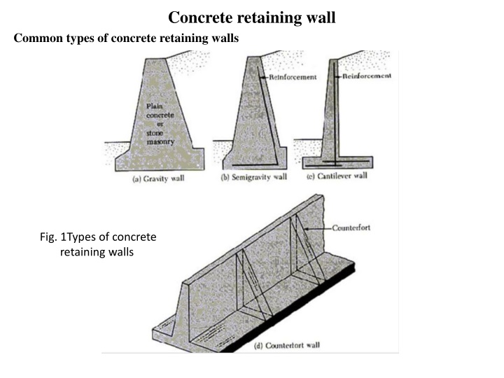
Concrete retaining wall Common types of concrete retaining walls Fig. 1Types of concrete retaining walls
Cantilever retaining wall The figure identifies the parts and terms used in retaining wall design. Cantilever walls have these principal uses at present: Principal terms used with retaining walls. Note that "toe" refers to both point O and the distance from front face similarly "heel" is point h or distance from backface of stem to h. of stem; Fig.2 Cantilever retaining wall details
1. For low walls of fairly short length, "low" being in terms of an exposed height on the order of 1 to 3.0 m and lengths on the order of 100 m or less. 2. Where the backfill zone is limited and/or it is necessary to use the existing soil as backfill. This restriction usually produces the condition of Fig.3, where the principal wall pressures are from compaction of the backfill in the limited zone defined primarily by the heel dimension. 3. In urban areas where appearance and durability justify the increased cost. Fig.3 Backfill was constructed from original ground
It is common, however, for the base width to be on the order of about 0.5H, which depends somewhat on the toe distance (B/3 is shown, but it is actually not necessary to have any toe). The thickness of the stem and base must be adequate for wide-beam shear at their intersections. The stem top thickness must be adequate for temperature- caused spalls and impacts from equipment/automobiles so that if a piece chips off, the remainder appears safe and provides adequate clear reinforcement cover. Fig.4 dimensions for a cantilever retaining wall. shown is optional Tentative design Batter
Wall pressure to use for shear and bending moment in stem design. Also shown is bearing capacity pressure based on Fig. 4-4 using B' =b -2e and L = L' = 1 unit. diagram
Wall pressure for overall stability against overturning and sliding. Wc = weight of all concrete (stem and base); Ws = weight of soil in zone acde. Find moment arms xi any way practical usually using parts of known geometry. Use this lateral pressure for base design and bearing capacity. It is common to use the Rankine Ka and = ? in (a). For ?' in (b) you may use ? or since the "slip" along ab is soil-to-soil. In any case compute Pav = Pah tan as being most nearly correct.
Wall stability The wall must be structurally stable against the following: 1. Stem shear and bending due to lateral earth pressure on the stem. This is a separate analysis using the stem height. (a) Wall pressure to use for shear and bending moment in stem design. Also shown is bearing capacity pressure diagram based on Fig. 4-4 using B' =b -2e and L = L' = 1 unit. (b) Wall pressure for overall stability against overturning and sliding. Wc = weight of all concrete (stem and base); Ws = weight of soil in zone acde. Find moment arms xi any way practical usually using parts of known geometry. Use this lateral pressure for base design and bearing capacity. 70 mm clear 50 or 70 mm clear "Virtual" back 2. Base shear and bending moments at the stem caused by the wall loads producing bearing pressure beneath the wall footing (or base). The critical section for shear should be at the stem faces for both toe and heel. Toe bending is seldom a concern but for heel bending the critical section should be taken at the approximate center of the stem reinforcement and not at the stem backface.
Sliding and Overturning Wall Stability The wall must be safe against sliding. That is, sufficient friction Fr must be developed between the base slab and the base soil that a safety factor SF is ??+?? ??? ?? = ?.?? ?? ? Note that for this computation the total vertical force R is R = R = Wc Wc + + Ws Ws + + P'av P'av We can compute a stability number No against overturning as ?? +???? ??? ??=?? ??= ?.? ?? ? The stability number in the given range should reflect the importance factor and site location. That is, if a wall failure can result in danger to human life or extensive damage to a major structure, values closer to 2.0 should be used. The location are best determined by dividing the wall and soil over the heel into rectangles and triangles so the areas (and masses) can be easily computed and the centroidal locations identified. Then it becomes a simple matter to obtain (Wc + Ws + P'av) = Pah - Pp p or