Computer Architecture and Input/Output Systems
Explore the world of computer architecture, input/output systems, external devices, I/O modules, and the challenges of I/O processing. Learn about the functions, structures, and interfaces involved in handling data transfer between CPU, memory, and peripherals. Discover the evolution of I/O functions and the characteristics of I/O channels.

Uploaded on Sep 16, 2024 | 1 Views
Download Presentation

Please find below an Image/Link to download the presentation.
The content on the website is provided AS IS for your information and personal use only. It may not be sold, licensed, or shared on other websites without obtaining consent from the author.If you encounter any issues during the download, it is possible that the publisher has removed the file from their server.
You are allowed to download the files provided on this website for personal or commercial use, subject to the condition that they are used lawfully. All files are the property of their respective owners.
The content on the website is provided AS IS for your information and personal use only. It may not be sold, licensed, or shared on other websites without obtaining consent from the author.
E N D
Presentation Transcript
Computer Architecture Prof. Dr. Nizamettin AYDIN naydin@yildiz.edu.tr nizamettinaydin@gmail.com http://www.yildiz.edu.tr/~naydin 1
Computer Architecture Input/Output 2
Outline Input/Output External Devices I/O Modules Module Function I/O Module Structure Programmed I/O Interrupt-Driven I/O Interrupt Processing Design Issues Direct Memory Access DMA Function I/O Channels and Processors The Evolution of the I/O Function Characteristics of I/O Channels The External Interface Types of Interfaces FireWire Thunderbolt InfiniBand 3
Input/Output A computer consists of a set of components or modules of three basic types that communicate with each other. CPU Memory Input/Output 4
Input/Output Problems Wide variety of peripherals Delivering different amounts of data At different speeds In different formats All slower than CPU and RAM Need I/O modules 5
Input/Output Module Interface to CPU and Memory Interface to one or more peripherals I/O Module Functions Control & Timing CPU Communication Device Communication Data Buffering Error Detection I/O Steps CPU checks I/O module device status I/O module returns status If ready, CPU requests data transfer I/O module gets data from device I/O module transfers data to CPU Variations for output, DMA, etc. 7
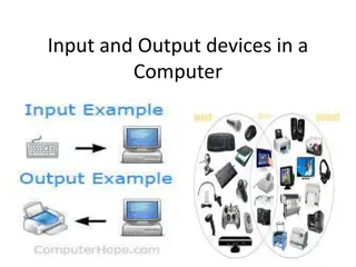
External Devices Human readable Screen, printer, keyboard Machine readable Monitoring and control Communication Modem Network Interface Card (NIC) 8
I/O Module Diagram Hide or reveal device properties to CPU Support multiple or single device Control device functions or leave for CPU Also O/S decisions 9
I/O Architectures I/O can be controlled in four general ways. Programmed I/O: Reserves a register for each I/O device. Each register is continually polled to detect data arrival. Interrupt-Driven I/O: allows the CPU to do other things until I/O is requested. Direct Memory Access (DMA): offloads I/O processing to a special-purpose chip that takes care of the details. Channel I/O: uses dedicated I/O processors. 10
Programmed I/O CPU has direct control over I/O Sensing status Read/write commands Transferring data CPU waits for I/O module to complete operation Wastes CPU time 12
Programmed I/O - detail CPU requests I/O operation I/O module performs operation I/O module sets status bits CPU checks status bits periodically I/O module does not inform CPU directly I/O module does not interrupt CPU CPU may wait or come back later 13
I/O Commands & Addressing I/O Devices Under programmed I/O data transfer is very like memory access (CPU viewpoint) Each device given unique identifier CPU commands contain identifier (address) CPU issues address Identifies module (& device if >1 per module) CPU issues command Control - telling module what to do e.g. spin up disk Test - check status e.g. power? Error? Read/Write Module transfers data via buffer from/to device 14
I/O Mapping Memory mapped I/O Devices and memory share an address space I/O looks just like memory read/write No special commands for I/O Large selection of memory access commands available Isolated I/O Separate address spaces Need I/O or memory select lines Special commands for I/O Limited set 15
Isolated I/O 17
Interrupt Driven I/O Overcomes CPU waiting No repeated CPU checking of device I/O module interrupts when ready Basic Operation CPU issues read command I/O module gets data from peripheral whilst CPU does other work I/O module interrupts CPU CPU requests data I/O module transfers data 18
CPU Viewpoint Issue read command Do other work Check for interrupt at the end of each instruction cycle If interrupted:- Save context (registers) Process interrupt Fetch data & store See Operating Systems notes 20
Design Issues Two design issues arise in implementing interrupt I/O. How do you identify the module issuing the interrupt? How do you deal with multiple interrupts? i.e. an interrupt handler being interrupted 22
Identifying Interrupting Module (1) Different line for each module Limits number of devices Software poll CPU asks each module in turn Slow Daisy Chain or Hardware poll Interrupt Acknowledge sent down a chain Module responsible places vector on bus CPU uses vector to identify handler routine Bus arbitration Module must claim the bus before it can raise interrupt e.g. PCI & SCSI 23
Multiple Interrupts Each interrupt line has a priority Higher priority lines can interrupt lower priority lines If bus mastering only current master can interrupt 24
Example - PC Bus 80x86 has one interrupt line 8086 based systems use one 8259A interrupt controller 8259A has 8 interrupt lines Sequence of Events 8259A accepts interrupts 8259A determines priority 8259A signals 8086 (raises INTR line) CPU Acknowledges 8259A puts correct vector on data bus CPU processes interrupt 25
ISA Bus Interrupt System ISA bus chains two 8259As together Link is via interrupt 2 Gives 15 lines 16 lines less one for link IRQ 9 is used to re-route anything trying to use IRQ 2 Backwards compatibility Incorporated in chip set 26
Direct Memory Access Interrupt driven and programmed I/O require active CPU intervention Transfer rate is limited CPU is tied up DMA is the answer Additional Module (hardware) on bus DMA controller takes over from CPU for I/O 30
DMA Operation CPU tells DMA controller:- Read/Write Device address Starting address of memory block for data Amount of data to be transferred CPU carries on with other work DMA controller deals with transfer DMA controller sends interrupt when finished 31
DMA Transfer - Cycle Stealing DMA controller takes over bus for a cycle Transfer of one word of data Not an interrupt CPU does not switch context CPU suspended just before it accesses bus i.e. before an operand or data fetch or a data write Slows down CPU but not as much as CPU doing transfer 32
DMA and Interrupt Breakpoints During an Instruction Cycle 33
DMA Configurations (1) Single Bus, Detached DMA controller Each transfer uses bus twice I/O to DMA then DMA to memory CPU is suspended twice 34
DMA Configurations (2) Single Bus, Integrated DMA controller Controller may support >1 device Each transfer uses bus once DMA to memory CPU is suspended once 35
DMA Configurations (3) Separate I/O Bus Bus supports all DMA enabled devices Each transfer uses bus once DMA to memory CPU is suspended once 36
Intel 8237A DMA Controller Interfaces to 80x86 family and DRAM When DMA module needs buses it sends HOLD signal to processor CPU responds HLDA (hold acknowledge) DMA module can use buses E.g. transfer data from memory to disk 1. Device requests service of DMA by pulling DREQ (DMA request) high 2. DMA puts high on HRQ (hold request), 3. CPU finishes present bus cycle (not necessarily present instruction) and puts high on HDLA (hold acknowledge). HOLD remains active for duration of DMA 4. DMA activates DACK (DMA acknowledge), telling device to start transfer 5. DMA starts transfer by putting address of first byte on address bus and activating MEMR; it then activates IOW to write to peripheral. DMA decrements counter and increments address pointer. Repeat until count reaches zero 6. DMA deactivates HRQ, giving bus back to CPU 37
Fly-By While DMA using buses processor idle Processor using bus, DMA idle Known as fly-by DMA controller Data does not pass through and is not stored in DMA chip DMA only between I/O port and memory Not between two I/O ports or two memory locations Can do memory to memory via register 8237 contains four DMA channels Programmed independently Any one active Numbered 0, 1, 2, and 3 39
I/O Channels and Processors Very large systems employ channel I/O. Channel I/O consists of one or more I/O processors (IOPs) that control various channel paths. CPU instructs I/O controller to do transfer Improves speed Takes load off CPU Dedicated processor is faster Slower devices such as terminals and printers are combined (multiplexed) into a single faster channel. On IBM mainframes, multiplexed channels are called multiplexor channels, the faster ones are called selector channels. 40
I/O Channels Channel I/O is distinguished from DMA by the intelligence of the IOPs. The IOP negotiates protocols, issues device commands, translates storage coding to memory coding, and can transfer entire files or groups of files independent of the host CPU. The host has only to create the program instructions for the I/O operation and tell the IOP where to find them. 41
A multiplexor channel A selector channel controls multiple high-speed devices at any one time, dedicated to the transfer of data with one of those devices. Each device, or a small set of devices, is handled by a controller, or I/O module, Thus, the I/O channel serves in place of the CPU in controlling these I/O controllers. can handle I/O with multiple devices at the same time. For low-speed devices, a byte multiplexor accepts or transmits characters as fast as possible to multiple devices. 42
I/O Channels A typical channel I/O configuration. 43
The external Interface The interface to a peripheral from an I/O module must be tailored to the nature and operation of the peripheral. One major characteristic of the interface is whether it is serial or parallel. In a parallel interface, there are multiple lines connecting the I/O module and the peripheral, and multiple bits are transferred simultaneously In a serial interface, there is only one line used to transmit data, and bits must be transmitted one at a time. A parallel interface has traditionally been used for higher-speed peripherals, such as tape and disk, while the serial interface has traditionally been used for printers and terminals. With a new generation of high-speed serial interfaces, parallel interfaces are becoming much less common. 44
The external Interface In either case, the I/O module must engage in a dialogue with the peripheral. In general terms, the dialogue for a write operation is as follows: The I/O module sends a control signal requesting permission to send data. The peripheral acknowledges the request. The I/O module transfers data (one word or a block depending on the peripheral). The peripheral acknowledges receipt of the data. 45
Point-to-Point and Multipoint Configurations A point-to-point interface provides a dedicated line between the I/O module and the external device. On small systems (PCs, workstations), typical point-to- point links include those to the keyboard, printer, and external modem. A typical example of such an interface is the EIA-232 specification EIA: Electronics Industry Alliance It is originally known as RS-232 i.e. Recommended Standard 232. It addresses signal voltages, signal timing, signal function, a protocol for information exchange, and either 25-pin or 9-pin mechanical connectors. 46
Point-to-Point and Multipoint Configurations Multipoint external interfaces, used to support external mass storage devices (disk and tape drives) and multimedia devices (CD- ROMs, video, audio). These multipoint interfaces are in effect external buses Two key examples: FireWire Thunderbolt InfiniBand. 47
IEEE 1394 FireWire High performance serial bus Fast Low cost Easy to implement Also being used in digital cameras, VCRs and TV FireWire Configuration Daisy chain Up to 63 devices on single port Up to 1022 buses can be connected with bridges Automatic configuration No bus terminators May be tree structure 48
FireWire 3 Layer Stack Physical Transmission medium, electrical and signaling characteristics Link Transmission of data in packets Transaction Request-response protocol 49


")


")
")
")