CO2-Laser-Driven Dielectric Laser Accelerator Proposal
Study and experimental demonstration of a CO2-laser-driven dielectric laser accelerator, addressing the limitations of current accelerator technologies by utilizing longer laser wavelengths for increased charge and improved beam control. The proposal aims to develop a novel in-vacuo scheme for ultra-compact laser-driven acceleration from MeV to GeV energies using grating structures, benefiting from the advantages of CO2 lasers. The project involves motivation, benefits of CO2-laser-driven DLA, and a developed quasi-analytic model for accelerator design.

Download Presentation

Please find below an Image/Link to download the presentation.
The content on the website is provided AS IS for your information and personal use only. It may not be sold, licensed, or shared on other websites without obtaining consent from the author.If you encounter any issues during the download, it is possible that the publisher has removed the file from their server.
You are allowed to download the files provided on this website for personal or commercial use, subject to the condition that they are used lawfully. All files are the property of their respective owners.
The content on the website is provided AS IS for your information and personal use only. It may not be sold, licensed, or shared on other websites without obtaining consent from the author.
E N D
Presentation Transcript
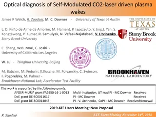
Materials Study and Experimental Demonstration of CO2-Laser-Driven Dielectric Laser Accelerator Proposal #304274 W. D. Kimura (STI Optronics), I. V. Pogorelsky (BNL), M. N. Polyanskiy (BNL), M. Fedurin (BNL), O. Solgaard (Stanford), J. Harris (Stanford), R. L. Byer (Stanford), R. J. England (SLAC), and L. Sch chter (Technion Israel Institute of Technology)* National Science Foundation (submitted, under review) *BSF-NSF (submitted, under review) 2019 ATF Users Meeting: New Proposal November 14-16, 2018
Motivation Dielectric laser accelerator (DLA) is in-vacuo scheme for achieving ultra-compact laser-driven acceleration from MeV to GeV energies [1] - Utilizes grating structure for accelerating electrons [2] - Channel gap separation is of order laser wavelength in size DLA experiments to-date used solid-state lasers - ~ 1 m gap ~ 1 m - Severely limits maxi- mum charge - Places high demands on e-beam emittance - Unless electrons are prebunched, only small fraction are accelerated [1] R. J. England, et al., Rev. Mod. Phys. 86, 1337 (2014). [2] T. Plettner, et al., Phys. Rev. ST Accel. Beams 9, 111301 (2006). 2
CO2-Laser-Driven DLA Offers Many Benefits Longer laser wavelength ( ~ 10 m) increases grating dimensions by 10X, i.e., gap ~ 10 m - Increases amount of charge by orders of magnitude - Eases focusing requirements of e-beam and permits using longer channels - Eases tolerance requirements when fabricating microstructures - Longer wavelength makes it easier to control phase of microbunches, which is important when staging DLA structures in series Using CO2-laser-driven inverse free electron laser (IFEL) provides convenient way to prebunch beam before sending electrons into DLA - Concept demonstrated at ATF during STELLA experiment [3] and by UCLA [4] who demonstrated ~96% trapping efficiency - Note, IFEL will not be part of this proposed program CO2lasers capable of 10 s kHz repetition rates - Provides high duty cycle needed for many applications [3] W. D. Kimura, et al., Phys. Rev. Lett. 92, 054801 (2004). [4] N. Sudar, et al., Phys. Rev. Lett. 120, 114802 (2018). 3
Developed Quasi-Analytic Model for DLA Model developed by Technion [5] calculates values for channel dimensions to satisfy resonant conditions for acceleration of electrons by EM wave in channel - Shows that 10- m light can yield same acceleration as 1- m light 1- m case 10- m case =1 m, r= 2.1, Sin=1TW/cm2 =10.6 m, r= 11.7, Sin = 1TW/cm2 1010 1010 L = 0.5 a = 0.25 d = 0.83 L = 0.5 a = 0.25 d = 0.87 Ninc=-1; 0 = 107o 109 109 Ninc=0; 0 = 73o Gradient [V/m] Gradient [V/m] 108 107 108 106 105 107 Ninc=0; 0 = 46.4o Ninc=1; 0 = 29o 104 Ninc=-2; 0 = 151o Ninc=-1; 0 = 133.6o 106 0.490 0.495 0.500 0.505 0.510 b / 103 0.4 0.5 b / 0.6 [5] A. Hanuka, et al., AIP Conference Proceedings, vol. 1812, 060012-6, March 2017. 4
Quasi-Analytic Model Results for CO2-Laser-Driven DLA Assumed 9 GW CO2 laser drive pulse (14.5 mJ in 1.6 ps) - Ignored possible anomalous absorption within Si substrate - Including reflection losses, estimate 8 1011 W/cm2 can be delivered - For 1-cm DLA, implies electron gain of >10 MeV 5
Orders of Magnitude Higher Charge Predicted Channel width now 10 m instead of ~1 m - However, channel height is unrestricted - Laser beam focus will be ~70 m tall; therefore, ideal e-beam focus shape would be elliptical, i.e., <10 m wide <70 m tall ATF able to focus e-beam down to 6 m (1 ) - Assuming n = 1 m and = 100, then for 1-cm long DLA, beta function would be 10.5 mm - E-beam radius (1 ) at entrance and exit to DLA would be 10.2 m - Assuming elliptical e-beam focus, implies roughly half of e-beam can pass through DLA channel At 1- m normalized emittance, e-beam charge is 500 pC for 50 MeV beam - Therefore, predict ~250 pC emitted from DLA - Solid-state-laser-driven DLA only produces ~1 fC; hence, CO2-laser-driven DLA experiment would demonstrate orders of magnitude higher charge 6
Mid-IR Optical Materials Critical DLA channel must be constructed from mid-infrared (MIR) optical material - Many MIR materials possible, e.g., Si, Ge, ZnSe, GaAs - Little data exists on their optical properties when exposed to high-peak- power, ultrashort-pulse CO2 laser radiation - Must tolerate exposure to high-energy e-beam - Must be amenable to micromachining to form channels with dimensions of order laser wavelength, i.e., 10 m From [6] From [7] [6] E. A. Peralta, et al., Nature 503, 91 94 (2013). [7] K. J. Leedle, et. al., Opt. Lett. 43, 2181 (2018). 7
Program Goals and Experimental Setup Program Goals: - Perform optical characterization measurements of candidate MIR optical materials at ATF using CO2 laser system and e-beam - Micromachine candidate MIR optical materials at Stanford to fabricate DLA channel for CO2-laser-driven DLA experiment - Perform proof-of-principle CO2-laser-driven DLA experiment at ATF as first time demonstration of MIR DLA Expose candidate MIR optical materials to CO2 laser beam and e-beam - Measure damage threshold (use 2 100 ps pulses, mJ/cm2 to J/cm2) - Measure nonlinear refractive effects, nonlinear absorption - Expose materials to direct impact by e-beam and observe any e-beam induced effects, e.g., color-center formation, charge buildup - Identify suitable materials for CO2-laser-driven DLA experiment that will be micromachined by Stanford into DLA structures 8
Experimental Setup (cont.) Basic setup for CO2-laser-driven DLA experiment - Would use vacuum chamber that has ports for CO2 laser beam - Electron energy spectrometer will be primary diagnostic 9
Plans Have requested 2-year program to NSF - Work will be conducted in parallel at ATF and Stanford - Technion will provide theoretical support through BSF-NSF program - One graduate student/postdoc will be working at Stanford; one graduate student/postdoc will be working at ATF 10
Electron Beam Requirements Parameter Nominal Requested Beam Energy (MeV) 50-65 Nominal values Bunch Charge (nC) 0.1-2.0 For exposure tests, need highest charge. For CO2-laser-driven DLA experiment, need ~500 pC. Compression Down to 100 fs (up to 1 kA peak current) Not needed Transverse size at IP (sigma, um) 30 100 (dependent on IP position) For exposure tests, not important. For CO2-laser-driven DLA experiment, need 6 microns Normalized Emittance (um) 1 (at 0.3 nC) For exposure tests, not important. For CO2-laser-driven DLA experiment, need 1 micron. Rep. Rate (Hz) 1.5 1.5 Hz Trains mode Single bunch Single bunch
CO2 Laser Requirements OPTION 2 (regen only, 1.5 or 3 Hz) Ideally would like 9 GW (1.6 ps, 14.5 mJ), less peak power is okay 9.25 m M^2 ~1.5 linear polarization Needs for MIR optical materials characterization measurements: - Energy, pulse length, and beam profile measurements - Diagnostic for measuring laser-induced damage - Diagnostics for measuring nonlinear refraction and absorption Needs for CO2-laser-driven DLA experiment: - Deliver two opposing laser beams into chamber housing DLA structure while controlling phase of two beams 12
2019 Experiment Time Estimates Run Hours (include setup time in hours estimate): Number of electron beam only hours: 16 Number of CO2laser hours delivered to laser experiment hall ( FEL room ): 120 Number of CO2 laser hours, + ebeam, delivered to electron beam experiment hall: 0 Overall % setup time: 30% Hazards & installation requirements: Large installation (chamber, insertion device, etc.): None Laser use (other than CO2): None Cryogens: None Introducing new magnetic elements: None Introducing new materials into the beam path: Yes Any other foreseeable beam line modifications: None 13


")