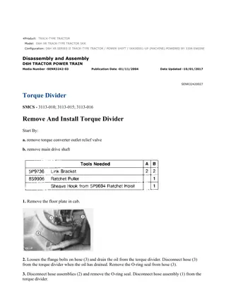
Caterpillar Cat D6H XR TRACK-TYPE TRACTOR (Prefix 7ZK) Service Repair Manual Instant Download (7ZK00001 and up)
Please open the website below to get the complete manualnn// n
Download Presentation

Please find below an Image/Link to download the presentation.
The content on the website is provided AS IS for your information and personal use only. It may not be sold, licensed, or shared on other websites without obtaining consent from the author. Download presentation by click this link. If you encounter any issues during the download, it is possible that the publisher has removed the file from their server.
E N D
Presentation Transcript
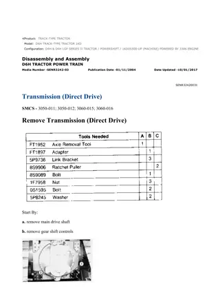
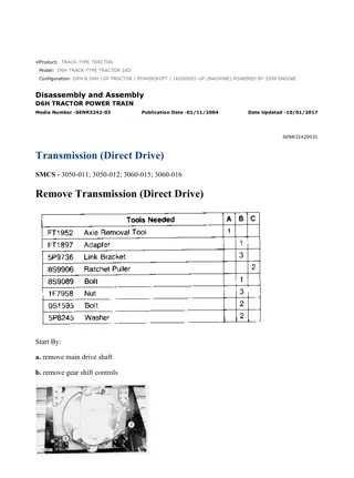
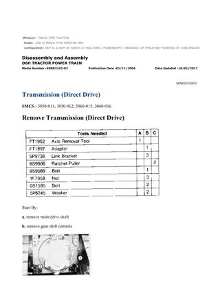
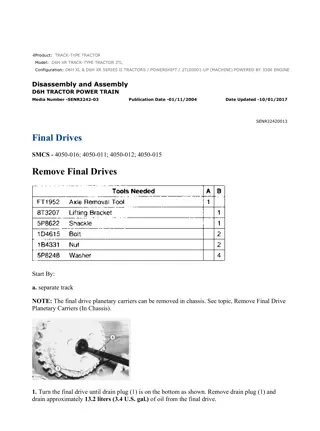
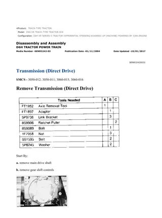
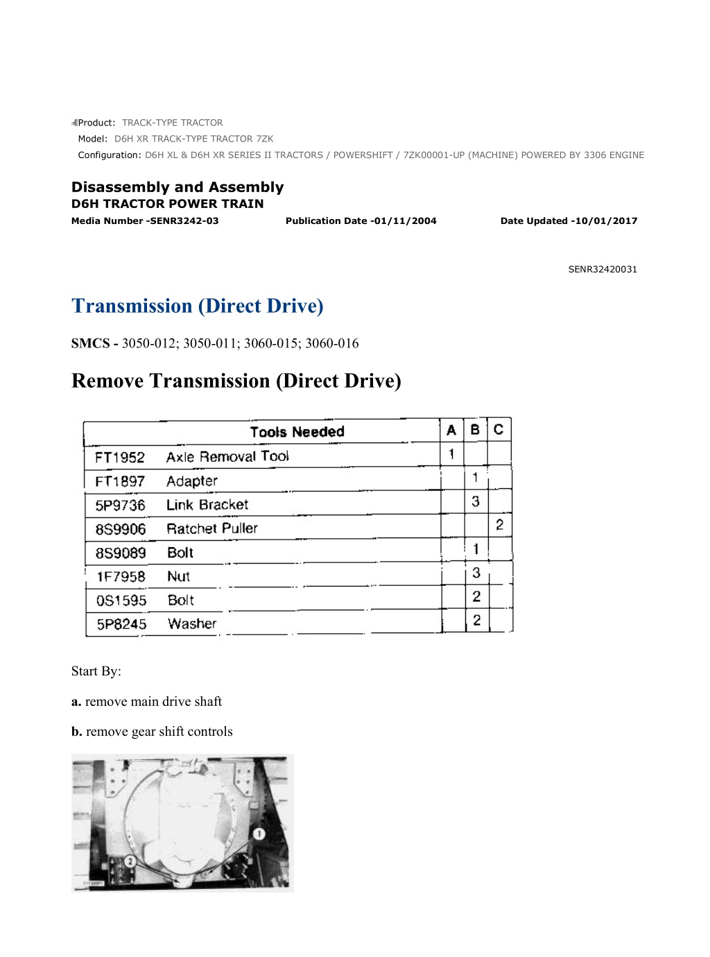
D6H XL & D6H XR SERIES II TRACTORS / POWERSHIFT / 7ZK00001-UP (MA... 1/46 Product: TRACK-TYPE TRACTOR Model: D6H XR TRACK-TYPE TRACTOR 7ZK Configuration: D6H XL & D6H XR SERIES II TRACTORS / POWERSHIFT / 7ZK00001-UP (MACHINE) POWERED BY 3306 ENGINE Disassembly and Assembly D6H TRACTOR POWER TRAIN Media Number -SENR3242-03 Publication Date -01/11/2004 Date Updated -10/01/2017 SENR32420031 Transmission (Direct Drive) SMCS - 3050-012; 3050-011; 3060-015; 3060-016 Remove Transmission (Direct Drive) Start By: a. remove main drive shaft b. remove gear shift controls https://127.0.0.1/sisweb/sisweb/techdoc/techdoc_print_page.jsp?returnurl=/sis... 2021/11/25
D6H XL & D6H XR SERIES II TRACTORS / POWERSHIFT / 7ZK00001-UP (MA... 2/46 1. Remove plug (1) from the bottom of the transmission and bevel gear case and drain the power train oil. Loosen the bolts that hold transmission suction screen cover (2) in place and drain the oil from the transmission case. Total oil drained will be approximately 129 liters (33.5 U.S. gal.). Install plug (1) and tighten the suction screen cover bolts. 2. Remove drive shaft yoke (2). Use forcing bolts and remove retainer (3) and the O-ring seal from the transmission and bevel gear case. 3. Remove the final drive cover and sun gear retainer from the final drive carrier. 4. Use tooling (A) and remove the inner and outer axle on each side of the machine. 5. Remove the cover and disconnect the two wires from the switch (6). Remove the clamp and move tube (4) out of the way. 6. Loosen bolt (5) and disconnect the linkage from the clutch control valve. https://127.0.0.1/sisweb/sisweb/techdoc/techdoc_print_page.jsp?returnurl=/sis... 2021/11/25
D6H XL & D6H XR SERIES II TRACTORS / POWERSHIFT / 7ZK00001-UP (MA... 3/46 7. Remove the cover and gasket, and install tooling (B). Attach a hoist to tooling (B). 8. Attach tooling (C) to both roller frames and to tooling (B) as shown. Because of the internal ramps, the transmission must roll down; it is necessary to use tooling (C) to control the transmission as it is separated from the transmission and bevel gear case. To prevent possible personal injury, it is necessary to make the transmission roll out slowly until it reaches the roller stops at the end of the tube assemblies. Four bolts (7) fasten the rear cover to the transmission. To prevent possible personal injury, four bolts (7) must be installed to remove the transmission. 9. Remove the 21 bolts that hold the transmission to the transmission and bevel gear case. Four bolts (7) should not be removed because they hold the rear cover to the transmission. 10. The weight of the transmission is 955 kg (2100 lb). Use forcing screws if necessary, and separate the transmission from the transmission and bevel gear case. Use tooling (C) and the hoist and slowly roll the transmission out to the roller stops on the tube assemblies. The transmission must be supported when the hoist is moved from the rear tube adapter [tooling (B)] to the top of the transmission. To prevent possible personal injury, make sure the support is on a solid footing so the transmission will not fall when the hoist is removed from tooling (B). https://127.0.0.1/sisweb/sisweb/techdoc/techdoc_print_page.jsp?returnurl=/sis... 2021/11/25
https://www.ebooklibonline.com Hello dear friend! Thank you very much for reading. Enter the link into your browser. The full manual is available for immediate download. https://www.ebooklibonline.com
D6H XL & D6H XR SERIES II TRACTORS / POWERSHIFT / 7ZK00001-UP (MA... 4/46 11. Put a floor jack (9) or wood blocks in position to support the transmission. Lower the transmission onto the support. 12. Remove the hoist from tooling (B). Attach the hoist to the top of the transmission. Remove tooling (C). Remove the transmission from the tube assemblies. 13. Remove large diameter O-ring seal (10) from the outer diameter of the transmission case. Remove four O-ring seals (9) and (11) from the transmission and bevel gear case. Install Transmission 1. Put clean oil on all of the O-ring seals. https://127.0.0.1/sisweb/sisweb/techdoc/techdoc_print_page.jsp?returnurl=/sis... 2021/11/25
D6H XL & D6H XR SERIES II TRACTORS / POWERSHIFT / 7ZK00001-UP (MA... 5/46 2. Install O-ring seal (10) onto the transmission. Install four O-ring seals (9) and (11) onto the transmission and bevel gear case. 3. Attach a hoist to the top of the transmission. 4. Put the transmission in position so the rollers are on the tube assemblies. The transmission must be supported when the hoist is moved from the top of the transmission to the rear tube adapter [tooling (B)]. To prevent possible personal injury, make sure the support is on a solid footing so the transmission will not fall when the hoist is removed from the top of the transmission. 5. Put a floor jack or wood blocks in position to support the transmission. Lower the transmission onto the support. 6. Install tooling (B) onto the transmission cover. Attach tooling (C) to both roller frames and tooling (B). 7. Remove the hoist from the top of the transmission and attach it to tooling (B). 8. Keep the transmission level with the hoist. Pull the transmission evenly into the transmission and bevel gear case with tooling (C). https://127.0.0.1/sisweb/sisweb/techdoc/techdoc_print_page.jsp?returnurl=/sis... 2021/11/25
D6H XL & D6H XR SERIES II TRACTORS / POWERSHIFT / 7ZK00001-UP (MA... 6/46 NOTE: It may be necessary to pull the transmission into the pilot diameter with longer bolts. 9. Install bolts (8) that hold the transmission into the transmission and bevel gear case. 10. Remove tooling (C). Remove tooling (B) and install the cover and gasket on the rear of the transmission. 11. Put tube (4) in position. Connect the wires to switch (6) and install the cover. Install the clamp that holds tube (4) in position. 12. Align the key on the shaft with the slot in the lever and install it. Tighten bolt (5). 13. Use two guide bolts and put the O-ring seal and retainer (3) in position. Install the six bolts and tighten them to a torque of 59 7 N m (44 5 lb ft). 14. Install drive shaft yoke (2). 15. Use tooling (A) and install the inner and outer axles on both sides. Make sure the first inner axle is not installed too far, or the opposite side inner axle will not go in far enough. 16. Install the O-ring and the cover on the final drive. 17. Fill the power train system with oil. See the Operation And Maintenance Guide for the correct oil and capacity. End By: https://127.0.0.1/sisweb/sisweb/techdoc/techdoc_print_page.jsp?returnurl=/sis... 2021/11/25
D6H XL & D6H XR SERIES II TRACTORS / POWERSHIFT / 7ZK00001-UP (MA... 7/46 a. install main drive shaft b. install gear shift controls Disassemble Transmission (Direct Drive) https://127.0.0.1/sisweb/sisweb/techdoc/techdoc_print_page.jsp?returnurl=/sis... 2021/11/25
D6H XL & D6H XR SERIES II TRACTORS / POWERSHIFT / 7ZK00001-UP (MA... 8/46 Start By: a. remove transmission (direct drive) b. remove clutch 1. Set the transmission on wood blocks. 2. Remove two O-ring seals (2). Remove orifice (1) from the transmission. 3. Install two 1/2 " - 13 x 50.8 mm (2 in) long bolts (4) to hold cover (5) in position when bolts (3) are removed. 4. Remove four bolts (3). 5. Install four 1/2 " - 13 guide bolts (6). https://127.0.0.1/sisweb/sisweb/techdoc/techdoc_print_page.jsp?returnurl=/sis... 2021/11/25
D6H XL & D6H XR SERIES II TRACTORS / POWERSHIFT / 7ZK00001-UP (MA... 9/46 6. Remove the cotter pin and pin (7). 7. The weight of cover (5) with clutch control valve (8) installed is 160 kg (350 lb). Separate the cover from the transmission a distance of 25.4 mm (1 in), and install tooling (A). 8. Attach a hoist to tooling (A), and remove cover (5) from the transmission. 9. Remove three O-ring seals (9), one O-ring seal (10), and one O-ring seal (12). 10. Remove two tubes (11) from the plate assembly. 11. Remove the O-ring seals from the two tubes. https://127.0.0.1/sisweb/sisweb/techdoc/techdoc_print_page.jsp?returnurl=/sis... 2021/11/25
D6H XL & D6H XR SERIES II TRACTORS / POWERSHIFT / 7ZK00001-UP (M... 10/46 12. Remove the eight bolts and three tube assemblies (13). 13. Remove three bolts (15). 14. Remove two bolts (17), tube assembly (14), and the clips. 15. Remove the two bolts and plate (18). 16. Remove bolt (16) and the transmission brake assembly. https://127.0.0.1/sisweb/sisweb/techdoc/techdoc_print_page.jsp?returnurl=/sis... 2021/11/25
D6H XL & D6H XR SERIES II TRACTORS / POWERSHIFT / 7ZK00001-UP (M... 11/46 17. Remove the two bolts and clips that hold tube assembly (19) in place. Disconnect tube assembly (19) from tube assembly (20), and remove tube assembly (19). 18. Remove the four bolts and tube assembly (20). 19. Remove tube assembly (22) from the transmission. 20. Remove 11 bolts (21) and the shifting assembly from the transmission. 21. Remove support assembly (23) from the shifting assembly. https://127.0.0.1/sisweb/sisweb/techdoc/techdoc_print_page.jsp?returnurl=/sis... 2021/11/25
D6H XL & D6H XR SERIES II TRACTORS / POWERSHIFT / 7ZK00001-UP (M... 12/46 22. Pull on shafts (25), and remove them from bracket assembly (24). 23. Remove four cotter pins (26). 24. Remove four plungers (27) and four springs (28) from bracket assembly (24). 25. Pins (29) prevent plungers (27) from rotating during operation. Remove pins (29) if necessary. 26. Remove cotter pin (30) and the washer. 27. Remove shaft (31) from bracket assembly (24). 28. Remove pin (33), and remove lever (32) from shaft (31). 29. If necessary, use a hammer and a punch, and remove pins (36). Remove guides (34) and forks (35) from shafts (25). https://127.0.0.1/sisweb/sisweb/techdoc/techdoc_print_page.jsp?returnurl=/sis... 2021/11/25
D6H XL & D6H XR SERIES II TRACTORS / POWERSHIFT / 7ZK00001-UP (M... 13/46 30. Remove the six bolts and cage assembly (37) and input shaft (38) from the transmission. 31. Use tool (B), and remove retaining ring (39). Remove input shaft (38) from cage (37). NOTE: Lip-type seal (41) will be damaged if it is removed. 32. If necessary, remove lip-type seal (41) from cage (37). 33. Remove O-ring seal (43) from the cage. 34. Remove spiral retaining ring (42) and bearing (40) from cage (37). https://127.0.0.1/sisweb/sisweb/techdoc/techdoc_print_page.jsp?returnurl=/sis... 2021/11/25
D6H XL & D6H XR SERIES II TRACTORS / POWERSHIFT / 7ZK00001-UP (M... 14/46 35. Install tooling (C), and attach a hoist. The weight of the transmission is 775 kg (1705 lb). Raise the transmission,and remove the six bolts and two support assemblies (44) from the transmission. 36. Use tooling (C), and lower the end of the transmission. Put the transmission in a vertical position on wood blocks. Remove tooling (C). 37. Remove 18 bolts and three cages (45) from the plate assembly. 38. Install tooling (C) onto plate assembly (47), and attach a hoist. 39. Remove 21 bolts (46). 40. The weight of plate assembly (47) with the pinion gear is 100 kg (220 lb). Remove plate assembly (47) with the pinion gear from the transmission. 41. Put plate assembly (47) with the pinion gear up on wood blocks. https://127.0.0.1/sisweb/sisweb/techdoc/techdoc_print_page.jsp?returnurl=/sis... 2021/11/25
D6H XL & D6H XR SERIES II TRACTORS / POWERSHIFT / 7ZK00001-UP (M... 15/46 42. Remove bolt (49) and retainer (50). 43. Remove the bearings and reverse idler gear (48) from the idler shaft. 44. Remove six bolts (52) that hold idler shaft (51) to plate assembly (47). 45. Install two 5P9736 Link Brackets [part of tooling (C)] to the plate assembly, and attach a hoist. Raise plate assembly (47) to be vertical. 46. Remove the four bolts and cover assembly (53). 47. Remove seal ring (54) from cover assembly (53). https://127.0.0.1/sisweb/sisweb/techdoc/techdoc_print_page.jsp?returnurl=/sis... 2021/11/25
D6H XL & D6H XR SERIES II TRACTORS / POWERSHIFT / 7ZK00001-UP (M... 16/46 48. Bend lockwasher (57) tab away from the groove in nut (56). Use tool (D), and remove nut (56). 49. Remove lockwasher (57) and washer (55) from the pinion assembly. To prevent possible personal injury from parts that may fall, make sure the pinion and gear assembly is supported before cage (58) is removed. 50. The weight of the pinion and gear assembly is 24 kg (53 lb). Put a nylon strap around the pinion and gear assembly, and attach a hoist. Use two 3/8 "-16 NC forcing screws in cage (58), and remove the bearing assembly, the ring, and cage (58). Remove the pinion and gear assembly from the plate assembly. 51. Use tooling (E) and remove bearing (59), spacer (60), and reverse gear assembly (61) from the pinion assembly. https://127.0.0.1/sisweb/sisweb/techdoc/techdoc_print_page.jsp?returnurl=/sis... 2021/11/25
D6H XL & D6H XR SERIES II TRACTORS / POWERSHIFT / 7ZK00001-UP (M... 17/46 52. Use tooling (F), and remove bearing (62) from reverse gear assembly (61). 53. Remove collar (64), hub (63) and forward gear assembly (65) from pinion assembly (66). 54. Use tooling (G), and remove bearing (67) from forward gear assembly (65). 55. Remove bearing (68) from pinion assembly (66). https://127.0.0.1/sisweb/sisweb/techdoc/techdoc_print_page.jsp?returnurl=/sis... 2021/11/25
D6H XL & D6H XR SERIES II TRACTORS / POWERSHIFT / 7ZK00001-UP (M... 18/46 56. Remove input transfer gear shaft (69) with brake plate (70), the input transfer gear, and the bearings from the transmission. 57. Use tooling (H) and a press, and remove bearing (71) and input transfer gear (72) from input transfer gear shaft (69). 58. Remove brake plate (70) from shaft (69). 59. Turn shaft (69) over, and use tooling (J) to remove bearing (73). 60. Bend the tab of lockwasher (75) away from the groove in nut (74). Use took (K), and loosen nut (74) while preventing the bevel gear from rotating, but do not remove it. 61. The weight of cage (76), the bevel gear, and the shaft is 46 kg (101 lb). Put a bar in position, and attach a lifting strap and a hoist. 62. Remove the 13 bolts from cage (76). Use two 1/2 "-13 NC forcing screws, and remove cage (76), the shims and the bevel gear from the transmission. Use the bar to counterbalance the weight of the bevel gear and shaft as they are removed. https://127.0.0.1/sisweb/sisweb/techdoc/techdoc_print_page.jsp?returnurl=/sis... 2021/11/25
D6H XL & D6H XR SERIES II TRACTORS / POWERSHIFT / 7ZK00001-UP (M... 19/46 63. Remove nut (74), lockwasher (75) and the washer from the bevel gear shaft and cage (76). 64. The weight of bevel gear (77) and shaft is 25 kg (55 lb). Use tooling (F) and a press, and remove bevel gear (77) and the shaft from cage (76). 65. Remove the 12 bolts that hold bevel gear (77) to bevel gear shaft (78). 66. Use tooling (F) and a press, and remove bevel gear shaft (78) from bevel gear (77). 67. Use tooling (J) and a press, and remove bearing (79) from bevel gear shaft (78). https://127.0.0.1/sisweb/sisweb/techdoc/techdoc_print_page.jsp?returnurl=/sis... 2021/11/25
D6H XL & D6H XR SERIES II TRACTORS / POWERSHIFT / 7ZK00001-UP (M... 20/46 68. Turn bevel gear shaft (78) over, and use tooling (J), and remove bearing (80) from bevel gear shaft (78). 69. Remove two bearing cups (81) and the ring that goes between them from cage (76). 70. Install tooling (L) into the end of two gear and shaft assemblies (82) and (83). Attach a hoist as shown. The weight of gear and shaft assembly (82) is 86 kg (190 lb). The weight of gear and shaft assembly (83) is 75 kg (165 lb). NOTE: Both gear and shaft assemblies (82) and (83) must be removed from transmission case (84) together. The gear and shaft assemblies cannot be removed separately. 71. Slowly, raise both gear and shaft assemblies (82) and (83) at the same time. Move the shaft assemblies slightly to avoid catching on the inside of transmission case (84), and remove them from the transmission case. https://127.0.0.1/sisweb/sisweb/techdoc/techdoc_print_page.jsp?returnurl=/sis... 2021/11/25
D6H XL & D6H XR SERIES II TRACTORS / POWERSHIFT / 7ZK00001-UP (M... 21/46 72. The following steps are for disassembly of input shaft and gear assembly (83). a. Use tooling (M), and remove bearing (85) from the input shaft. b. Use tool (N), and remove retaining ring (87) from input shaft (86). c. Remove spacer (88), input transfer gear (89), and pinion gear (95) from input shaft (86). d. Remove spacer (90), pinion gear (96), pinion gear (91), and spacer (97) from the input shaft. e. Remove pinion gear (92), pinion gear (98), spacer (93), and pinion gear (99) from input shaft (86). f. If necessary, use tooling (M), and remove bearing (94) from input shaft (86). g. Use tool (N), and remove retaining ring (100) from the input shaft. https://127.0.0.1/sisweb/sisweb/techdoc/techdoc_print_page.jsp?returnurl=/sis... 2021/11/25
D6H XL & D6H XR SERIES II TRACTORS / POWERSHIFT / 7ZK00001-UP (M... 22/46 73. The following steps are for disassembly of countershaft and gear assembly (82). a. Use tool (N), and remove one retaining ring (101) from each end of countershaft and gear assembly (82). b. Install tooling (O), and remove bearing (102) from the countershaft and gear assembly. Use tooling (O), and remove the bearing at the other end of countershaft and gear assembly (82). c. Remove reverse pinion gear (103), spacer (106), forward pinion gear (107) and sixth gear assembly (104) from countershaft (105). d. Remove first gear assembly (109) and collar (108) from the countershaft. 3. Use tool (P), and remove retaining ring (115). Remove hub (113) and second gear assembly (112). g. Use tool (P), and remove retaining ring (114). Remove hub (110) and fifth gear assembly (111). https://127.0.0.1/sisweb/sisweb/techdoc/techdoc_print_page.jsp?returnurl=/sis... 2021/11/25
Suggest: For more complete manuals. Please go to the home page. https://www.ebooklibonline.com If the above button click is invalid. Please download this document first, and then click the above link to download the complete manual. Thank you so much for reading
D6H XL & D6H XR SERIES II TRACTORS / POWERSHIFT / 7ZK00001-UP (M... 23/46 i. Use tool (N), and remove retaining ring (117). j. Remove third gear assembly (116) and collar (118) from countershaft (105). k. Use tool (P), and remove retaining ring (120). l. Remove hub (122) and fourth gear assembly (119). m. Use tool (P), and remove retaining ring (121) from countershaft (105). 74. Remove the six bolts. Use forcing screws, and remove cage (123) from the transmission case. 75. Remove the six bolts, use forcing screws, and remove cage assembly (124) from the transmission case. 76. Remove seal ring (125) from cage assembly (124). 77. Remove bearing cup (126) from cage assembly (124). https://127.0.0.1/sisweb/sisweb/techdoc/techdoc_print_page.jsp?returnurl=/sis... 2021/11/25
D6H XL & D6H XR SERIES II TRACTORS / POWERSHIFT / 7ZK00001-UP (M... 24/46 78. Repeat Step 75 and Step 76 on cage assembly (45), that was removed from the other end of countershaft (82) in Step 36. 79. Remove bearing cup (127) from cage (123). 80. Remove bearing cup (128) from cage (45). Cage (45) was removed from shaft (83) in Step 36. 81. Remove bearing cup (129) and the ring under it from the transmission case. 82. Remove plug (132). Use a 1/4 "-20 NC bolt,and remove the dowel behind the plug. Remove bearing race (130). 83. Remove plug (133). Use a 10 - 32 NF screw, and remove the dowel behind the plug. Remove bearing race (131). Assemble Transmission (Direct Drive) https://127.0.0.1/sisweb/sisweb/techdoc/techdoc_print_page.jsp?returnurl=/sis... 2021/11/25
https://www.ebooklibonline.com Hello dear friend! Thank you very much for reading. Enter the link into your browser. The full manual is available for immediate download. https://www.ebooklibonline.com

