Caterpillar Cat D6H LS SERIES II TRACTOR (Prefix 2DK) Service Repair Manual Instant Download (2DK05500 and up)
Please open the website below to get the complete manualnn// n
Download Presentation

Please find below an Image/Link to download the presentation.
The content on the website is provided AS IS for your information and personal use only. It may not be sold, licensed, or shared on other websites without obtaining consent from the author. Download presentation by click this link. If you encounter any issues during the download, it is possible that the publisher has removed the file from their server.
E N D
Presentation Transcript
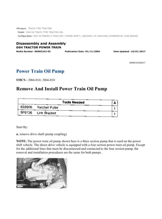
w 1/11(W) Product: TRACK-TYPE TRACTOR Model: D6H II TRACK-TYPE TRACTOR 2DK Configuration: D6H LS SERIES II TRACTOR / POWERSHIFT / 2DK05500-UP (MACHINE) POWERED BY 3306 ENGINE Disassembly and Assembly D6H TRACTOR POWER TRAIN Media Number -SENR3242-03 Publication Date -01/11/2004 Date Updated -10/01/2017 SENR32420017 Power Train Oil Pump SMCS - 3066-010; 3066-016 Remove And Install Power Train Oil Pump Start By: a. remove drive shaft (pump coupling) NOTE: The power train oil pump shown here is a three section pump that is used on the power shift vehicle. The direct drive vehicle is equipped with a four section power train oil pump. Except for the additional lines that must be disconnected and connected to the four section pump, the removal and installation procedures are the same for both pumps. https://127.0.0.1/sisweb/sisweb/techdoc/techdoc_print_page.jsp?returnurl=/sisweb/siswe... 2022/2/7
w 2/11(W) 1. Put identification marks on the wires and disconnect them from switch (1). 2. Remove two bolts (6) that hold the tube assembly to the power train oil pump. 3. Disconnect hose assemblies (3) and (5) from the power train oil pump. 4. Install the 5P9736 Link Bracket [part of tooling (A)] to the ceiling of the cab, using the right side threaded hole. Attach the 8S9906 ratchet puller to the link bracket. 5. The weight of the direct drive four section power train oil pump is 50 kg (110 lb). The weight of the power shift three section power train oil pump is 39 kg (85 lb). Put a nylon strap around the pump and attach tooling (A). NOTICE Remove the plastic strap that fastens wiring harness (7) to the frame to prevent damage from the ratchet puller and pump. 6. Remove four bolts (2) and two nuts (4). Use tooling (A) and remove the pump. 7. Remove the four O-ring seals from the cover. NOTE: The following steps are for installation of the power train oil pump. 8. Use tooling (A) and put the power train oil pump in position. Install four bolts (2) and two nuts (4). 9. Connect hose assemblies (3) and (5) to the pump. Make sure the O-ring seals on the tube assembly are in position, and install two bolts (6). 10. Connect the wires to switch (1). 11. Check, and fill the power train system with oil. See the Operation and Maintenance Guide for the type of oil and capacity. https://127.0.0.1/sisweb/sisweb/techdoc/techdoc_print_page.jsp?returnurl=/sisweb/siswe... 2022/2/7
w 3/11(W) End By: a. install drive shaft (pump coupling) Disassemble Power Train Oil Pump Start By: a. remove power train oil pump. NOTE: The power train oil pump used on the power shift machine is a three section pump. A four section pump is used on the direct drive machine. The four section pump has been illustrated here, but the disassembly and assembly procedures are similar for both pumps. To clarify any differences and for identification of the individual pump sections, see the Specification module, Form No. SENR3239. 1. Remove switch (3). Remove four bolts (2) and flange (1) with the cage from the pump. 2. Remove two bolts (4). https://127.0.0.1/sisweb/sisweb/techdoc/techdoc_print_page.jsp?returnurl=/sisweb/siswe... 2022/2/7
https://www.ebooklibonline.com Hello dear friend! Thank you very much for reading. Enter the link into your browser. The full manual is available for immediate download. https://www.ebooklibonline.com
w 4/11(W) 3. Remove O-ring seal (5) from cage (6). Remove spiral snap ring (8) from flange (1). 4. Use tooling (A) and a press, and remove flange (1) from cage (6). If necessary, remove plug (7) from the flange. 5. Use tooling (B), and remove the bearing and lip-type seal from cage (6). NOTICE Put identification marks on the pump gears. If the pump gears are reused, they should be installed into their original position. 6. Turn the pump over, and support it with wood blocks as shown. 7. Remove the four O-ring seals and four bolts (10) from cover (9). Remove the cover. Turn cover (9) over, and remove the two O-ring seals. 8. Remove two gears (12). Remove the key from gear assembly (11). 9. Remove the two O-ring seals and body assembly (13). Turn body assembly (13) over, and remove the three O-ring seals and the two dowels. https://127.0.0.1/sisweb/sisweb/techdoc/techdoc_print_page.jsp?returnurl=/sisweb/siswe... 2022/2/7
w 5/11(W) 10. Remove two gears (14). Remove the key from gear assembly (11). 11. Remove body assembly (15). Turn body assembly (15) over, and remove the O-ring seal. Use tooling (B), and remove the two bearings. 12. Remove gear assembly (16). 13. Turn the pump over, and support with wood blocks as shown. Remove cover assembly (17). 14. Turn cover assembly (17) over, and remove the O-ring seal. Use tooling (B), and remove the two bearings. 15. Remove two gears (18) and (19). Remove the key from gear assembly (11). 16. Remove body assembly (20) and gear assembly (11) from body assembly (21). https://127.0.0.1/sisweb/sisweb/techdoc/techdoc_print_page.jsp?returnurl=/sisweb/siswe... 2022/2/7
w 6/11(W) 17. Turn body assembly (20) over, and remove the O-ring seal. Use tooling (B), and remove the O -ring seal. Use tooling (B), and remove the two bearings. 18. Remove the dowels from body assemblies (20) and (21). Assemble Power Train Oil Pump 1. Make sure all parts are clean and free of foreign material. Inspect all parts for wear or damage, and replace if necessary. Put clean oil on all parts at assembly. 2. Install four dowels (2), two on each side, in body assembly (1). The dowels should be 5.0 0.5 mm (.200 .020 in) above the surface of body assembly (1). NOTICE Install bearings (3) with the joint in both bearings in the correct location in the body assembly. The location of the joint is at an angle https://127.0.0.1/sisweb/sisweb/techdoc/techdoc_print_page.jsp?returnurl=/sisweb/siswe... 2022/2/7
w 7/11(W) 30 15 from the centerline of the two bearing bores in the direction of the groove on the pressure side of pump. 3. Use tooling (A) and a press, and install two bearings (4) into body assembly (6). The bearings must be 1.5 0.25 mm (.059 .020 in) below the surface of the body. 4. Install O-ring seal (5) on body assembly (6). 5. Position body assembly (1) on wood blocks as shown. Align the dowels, and put body assembly (6) in position on body assembly (1). 6. Install two dowels (9) into body assembly (6). The dowels should be 5.0 0.5 mm (.200 .020 in) above the surface of body assembly (6). 7. Install gear assembly (7) into the body assemblies with the splined end of the shaft up as shown. Put the key in position, and install two gears (8). NOTICE Install two bearings (11) with the joint in both bearings in the correct location. The location of the joint is at an angle 30 15 from the centerline of the two bearing bores in the direction of the groove on the pressure side of the pump. See illustration C2910P1. https://127.0.0.1/sisweb/sisweb/techdoc/techdoc_print_page.jsp?returnurl=/sisweb/siswe... 2022/2/7
w 8/11(W) 8. Use tooling (A) and a press, and install two bearings (11) into body assembly (10). The bearings must be 1.5 0.25 mm (.059 .020 in) below the surface of the body. 9. Install O-ring seal (12) on body assembly (10). 10. Turn body assembly (10) over, and put it in position on body assembly (6). Make sure O-ring seal (12) stays in position when the body is turned over. 11. Turn the pump assembly over, and install gear assembly (13). NOTICE Install two bearings (15) with the joint in both bearings in the correct location. The location of the joint is at an angle 30 15 from the centerline of the two bearing bores in the direction of the groove on the pressure side of the pump. See illustration C2910P1. 12. Use tooling (A) and a press, and install two bearings (15) into body assembly (14). The bearings must be 1.5 0.25 mm (.059 .020 in) below the surface of the body. https://127.0.0.1/sisweb/sisweb/techdoc/techdoc_print_page.jsp?returnurl=/sisweb/siswe... 2022/2/7
w 9/11(W) 13. Install O-ring seal (16) onto body assembly (14). 14. Turn body assembly (14) over, and put it in position on body assembly (1). Make sure O-ring seal (16) stays in position when the body assembly is turned over. 15. Put the key in position in the groove on gear assembly (7). Install two gears (17). 16. Install two dowels (19) in body assembly (18). The dowels should be 5.0 0.5 mm (.200 .020 in) above the surface of body assembly (18). 17. Install three O-ring seals (20) onto body assembly (18). 18. Turn body assembly (18) over, and install it onto body assembly (14). Make sure three O-ring seals (20) stay in position. 19. Put the key in the groove in gear assembly (7). Install two gears (22). 20. Install two O-ring seals (21). https://127.0.0.1/sisweb/sisweb/techdoc/techdoc_print_page.jsp?returnurl=/sisweb/siswe... 2022/2/7
w 10/11(W) 21. Install two O-ring seals (24) in cover (23). 22. Turn cover (23) over, and install it on body assembly (18). Install four bolts and washers (25). 23. Install the four O-ring seals on cover (23). 24. Put 7M7260 Liquid Gasket Material on the outer diameter of the lip-type seal. Use tool (A) and a press, and install the lip-type seal into cage (26). Put clean oil on the lip of the seal. 25. Use tool (A) and a press, and install the bearing into cage (26). 26. Clean the outer diameter of the plug that goes in flange (27), and put 7M7260 Liquid Gasket Material on it. Use tool (A), and install the plug until it is 1.25 0.25 mm (.05 .010 in) below the surface of the flange. https://127.0.0.1/sisweb/sisweb/techdoc/techdoc_print_page.jsp?returnurl=/sisweb/siswe... 2022/2/7
w 11/11(W) 27. Use tool (A) and a press, and install flange (27) into cage (26). 28. Install spiral snap ring (29) and O-ring seal (28) onto the cage assembly. 29. Put the cage assembly and flange (27) in position, and install four bolts (30), and tighten to a torque of 30 4 N m (22 4 lb ft). 30. Install two bolts (32) and switch (31). 31. Make sure the pump turns freely by hand before and after installation onto the case and frame. End By: a. install power train oil pump https://127.0.0.1/sisweb/sisweb/techdoc/techdoc_print_page.jsp?returnurl=/sisweb/siswe... 2022/2/7
w 1/5(W) Product: TRACK-TYPE TRACTOR Model: D6H II TRACK-TYPE TRACTOR 2DK Configuration: D6H LS SERIES II TRACTOR / POWERSHIFT / 2DK05500-UP (MACHINE) POWERED BY 3306 ENGINE Disassembly and Assembly D6H TRACTOR POWER TRAIN Media Number -SENR3242-03 Publication Date -01/11/2004 Date Updated -10/01/2017 SENR32420018 Priority Valve SMCS - 3180-010; 3180-015; 3180-016 Remove And Install Priority Valve 1. Remove four bolts (2). 2. Remove bolts (1), and remove the cover and gasket. 3. Pull adapter (3), and remove it from the tubes. https://127.0.0.1/sisweb/sisweb/techdoc/techdoc_print_page.jsp?returnurl=/sisweb/siswe... 2022/2/7
w 2/5(W) 4. Remove two tubes (5) and the four O-ring seals. NOTE: To make the transmission control cable pin assemblies easier to remove: a. The transmission control lever should be in 3R to remove the pin assembly from speed control cable (6). b. The transmission control lever should be in NF to remove the pin assembly from directional control cable (4). 5. Remove the pin assemblies, and disconnect directional control cable (4) and speed control cable (6) from the priority valve. 6. Remove the four bolts that hold two covers (7). Remove two control cables (4) and (6) from the transmission cover. 7. Remove two plugs (9), tubes (8), the springs, and the O-ring seals from the transmission cover. 8. Remove four bolts (10), and remove the priority valve. 9. Remove the two O-ring seals from the priority valve. 10. Reverse the order of Step 1 through Step 9, and install the priority valve. Disassemble Priority Valve https://127.0.0.1/sisweb/sisweb/techdoc/techdoc_print_page.jsp?returnurl=/sisweb/siswe... 2022/2/7
w 3/5(W) Start By: a. remove priority valve 1. Remove O-ring seals (1). Remove pins (6), washers (5), levers (3) and washers (3) from the shafts. Cover (4) holds a spring under compression to prevent possible personal injury, loosen the bolts slowly and evenly until the spring compression is released. 2. Loosen the two bolts evenly, and remove cover (4) and the valve spool from the valve body. 3. Remove spring (7), shims (8) and slug (10) from valve spool (9). 4. Remove retaining ring (14) with tool (A). Remove retainer (13), spring (12) and plunger (11) from the valve spool. 5. Use tool (B), and remove two retaining rings (17) from dowels (16). Remove dowels (16) from levers (2). 6. Remove bearings (15) from levers (2) with tooling (C) and a press. https://127.0.0.1/sisweb/sisweb/techdoc/techdoc_print_page.jsp?returnurl=/sisweb/siswe... 2022/2/7
w 4/5(W) 7. Use a hammer and a punch, and push pins (19) from the valve body. Remove shafts (18) from the valve body. 8. Inspect all parts for damage, and make replacements if needed. Assemble Priority Valve 1. Put clean oil on the parts before assembly. 2. Slide shafts (2) into the valve body. Align the holes in the shafts with the holes in the valve body, and install pins (1). 3. Install plunger (8), spring (9) and retainer (10) into valve spool (6). Use tool (A), and install retaining ring (11) in the valve spool. 4. Install shims (5), spring (4) and slug (7) into valve spool (6). https://127.0.0.1/sisweb/sisweb/techdoc/techdoc_print_page.jsp?returnurl=/sisweb/siswe... 2022/2/7
w 5/5(W) 5. Install valve spool (6) into the valve body. The spring end of the spool goes into the valve body first, and the slug is against the inside surface of cover (3). 6. Install cover (3) onto the valve body. 7. Use tooling (B) and a press to install bearings (12) in levers (13). The bearings must be even with the outside surface of the levers. The inside diameter of the bearing must be 19.120 0.038 mm (.7528 .0015 in) after assembly. 8. Slide dowels (14) in place in levers (13), and install retaining rings (15) with tool (A) to hold the dowels in place. 9. Slide washers (17), levers (20) and washers (18) on the dowels. Install pins (19) to hold the washers and levers in place. 10. Install two O-ring seals (16) on the valve body. End By: a. install priority valve https://127.0.0.1/sisweb/sisweb/techdoc/techdoc_print_page.jsp?returnurl=/sisweb/siswe... 2022/2/7
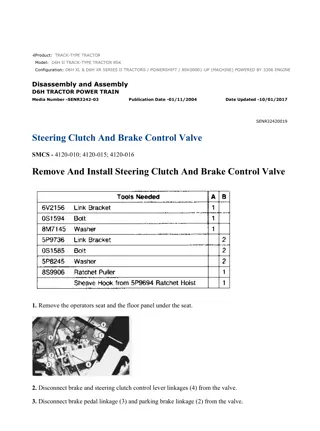
w 1/12(W) Product: TRACK-TYPE TRACTOR Model: D6H II TRACK-TYPE TRACTOR 2DK Configuration: D6H LS SERIES II TRACTOR / POWERSHIFT / 2DK05500-UP (MACHINE) POWERED BY 3306 ENGINE Disassembly and Assembly D6H TRACTOR POWER TRAIN Media Number -SENR3242-03 Publication Date -01/11/2004 Date Updated -10/01/2017 SENR32420019 Steering Clutch And Brake Control Valve SMCS - 4120-010; 4120-015; 4120-016 Remove And Install Steering Clutch And Brake Control Valve 1. Remove the operators seat and the floor panel under the seat. 2. Disconnect brake and steering clutch control lever linkages (4) from the valve. https://127.0.0.1/sisweb/sisweb/techdoc/techdoc_print_page.jsp?returnurl=/sisweb/siswe... 2022/2/7
w 2/12(W) 3. Disconnect brake pedal linkage (3) and parking brake linkage (2) from the valve. 4. Install tooling (A) onto the valve. 5. Install the 5P9736 Link Brackets [part of tooling (B)] at the rear upper corners inside the cab. Attach the 8S9906 ratchet puller and the sheave hook from the 5P9694 ratchet hoist to tooling (A) as shown. 6. Clean the dirt and debris from the valve and surrounding area. 7. Remove four bolts (1). 8. The weight of the steering and brake control valve is 43 kg (95 lb). Use tooling (A) and (B) and carefully remove the steering and brake control valve. 9. Remove the plate and the twelve O-ring seals that are under the steering clutch and brake control valve. NOTE: The following steps are for installation of the steering clutch and brake control valve. 10. Put 5P0960 Multipurpose Grease on the twelve O-ring seals and install the plate and the O- ring seals in position. 11. Use tooling (A), (B), and two 3/8 - 16 guide boltsand put steering clutch and brake control valve in position on the plate. Install four bolts (1) and tighten them to a torque of 51 4 N m (38 3 lb ft). Remove tooling (A) and (B). 12. Connect parking brake linkage (2), brake pedal linkage (3), and control lever linkages (4). 13. Install the floor panel and the operators seat. Disassemble Steering Clutch And Brake Control Valve Start By: a. remove steering clutch and brake control valve https://127.0.0.1/sisweb/sisweb/techdoc/techdoc_print_page.jsp?returnurl=/sisweb/siswe... 2022/2/7
w 3/12(W) 1. Remove two springs (2), the two bolts and bracket (3) from the valve. 2. Loosen the bolt, and remove the bellcrank (1) from the valve. 3. Remove key (5) from the shaft. 4. Use tooling (A) to remove retaining ring (4) and the washer. 5. Remove bolts (6), and remove the cover and gasket. 6. Loosen the bolts, and remove three levers (7) and (9). 7. Put identification marks on four spool assemblies (8) for assembly purposes. Remove the four spool assemblies from the valve. https://127.0.0.1/sisweb/sisweb/techdoc/techdoc_print_page.jsp?returnurl=/sisweb/siswe... 2022/2/7
w 4/12(W) 8. Use tool (B), and remove retaining ring (12) from spool assembly (10). 9. Remove washer (14), spring (11) and shims (13) from the spool assembly. 10. Use tool (C), and remove retaining ring (15) from spool assembly (10). 11. Remove plunger (17), spring (16), and ball (18) from the spool assembly. NOTE: Step 8 through Step 11 should be repeated for four spool assemblies. Keep the shims (13) with their individual spool for assembly purposes. 12. Remove two bolts (20) and washers. Remove two spring assemblies (19) from the valve. Remove the O-ring seals from the washers. 13. Remove the bolt and spring (21) from block (22). Remove the retaining rings, pin and two bearings (23). 14. Remove two bolts (26) and washers. https://127.0.0.1/sisweb/sisweb/techdoc/techdoc_print_page.jsp?returnurl=/sisweb/siswe... 2022/2/7
w 5/12(W) 15. Remove bolt (24) and retainer. 16. Put identification marks on four plungers for assembly purposes. Remove four plungers (25) and the four springs. 17. Rotate shaft (28), and remove the bolt and washer. Remove shaft (28) from lever assembly (30), spacer (29), washer (27) and the valve body. 18. Remove the retaining rings, pin and two bearings from the lever assembly. 19. Remove two bolts (31) and washers from the lever assemblies. 20. Remove the key from shaft (33). Use tool (A), and remove the retaining ring and washer (32) from both sides. 21. Remove shaft (33) from two lever assemblies (34) and the valve housing. 22. Remove the retaining rings, pin and two bearings from the lever assemblies. 23. Remove plug (37). 24. Remove three lip-type seals (36) and six roller bearings (38). 25. Remove the four bolts and cover (35) and gasket. https://127.0.0.1/sisweb/sisweb/techdoc/techdoc_print_page.jsp?returnurl=/sisweb/siswe... 2022/2/7
w 6/12(W) 26. Remove the bolt from lever (39). Remove shaft (40) from lever (39) and the valve body. Remove lever (39) from the valve body. 27. Remove lip-type seal (41) and two bearings from the valve body. 28. Remove seat (43), the two O-ring seals, valve (44), spring (42) and valve (45) from location (X) on the bottom of the valve body. 29. If necessary, carefully remove seat (46) from the valve body with a hammer and a punch. Assemble Steering Clutch And Brake Control Valve 1. Inspect O-ring seals and gaskets for damage, and replace if necessary. Make sure the valve bodies and all parts of the valve are clean. Put clean hydraulic oil on all of the parts. https://127.0.0.1/sisweb/sisweb/techdoc/techdoc_print_page.jsp?returnurl=/sisweb/siswe... 2022/2/7
w 7/12(W) 2. Install seat (2), valve (5), spring (1), valve (4) and seat (3) with two O-ring seals into location (X) in the valve body. NOTICE When installing the outer bearing in Step 3, use tooling (A) on the stamped end of the bearing only. 3. Use tooling (A), and install the two bearings. 4. Put 7M7260 Liquid Gasket Material on the seal bore, and let it dry. Install lip-type seal (8) with the lip of the seal toward the inside of the valve body with tooling (A). 5. Put lever (6) into position in the valve body, and install shaft (7) into the valve body and lever (6). Install the bolt and washer into lever (6). 6. Put cover (9) and the gasket in position, and install the four bolts. NOTICE https://127.0.0.1/sisweb/sisweb/techdoc/techdoc_print_page.jsp?returnurl=/sisweb/siswe... 2022/2/7
Suggest: For more complete manuals. Please go to the home page. https://www.ebooklibonline.com If the above button click is invalid. Please download this document first, and then click the above link to download the complete manual. Thank you so much for reading
w 8/12(W) When installing bearings (12) in Step 7, use tooling (A) on the stamped end of the bearings only. 7. Use tooling (A), and install six bearings (12) into the valve body. 8. Put 7M7260 Liquid Gasket Material on the plug bore, and let it dry. Use tooling (A), and install plug (11) into the valve body. 9. Put 7M7260 Liquid Gasket Material on the seal bores, and let it dry. Use tooling (A), and install three seals (10) with the lip of the seal toward the inside of the valve body. 10. Install pin (13) into two bearings (16) and lever (14). Install retaining ring (15) onto the pin. 11. Put levers (20) in position in the valve body. Install shafts (19) into the valve body and lever assemblies (20). 12. Put washers (18) in position on shafts (19), and use tool (C) to install the retaining rings on the shafts. 13. Install the keys on shafts (19) both sides. 14. Rotate shafts (19) to align the holes, and install the two bolts (17) and washers. https://127.0.0.1/sisweb/sisweb/techdoc/techdoc_print_page.jsp?returnurl=/sisweb/siswe... 2022/2/7
w 9/12(W) 15. Install pin (21) into two bearings (24) and lever (22). Install retaining ring (23) onto the pin. 16. Put lever assembly (28) in position in the valve body, and install shaft (26) into the valve body, washer (25), spacer (27) and lever assembly (28). 17. Rotate shaft (26) to align the holes, and install the bolt and washer. 18. Install the four springs and four plungers (29) into the original location. 19. Install two bolts (31) and washers. Install bolt and retainer (30) into the valve body to hold the plungers in place. https://127.0.0.1/sisweb/sisweb/techdoc/techdoc_print_page.jsp?returnurl=/sisweb/siswe... 2022/2/7
https://www.ebooklibonline.com Hello dear friend! Thank you very much for reading. Enter the link into your browser. The full manual is available for immediate download. https://www.ebooklibonline.com

