Caterpillar Cat CS54B, CP54B Vibratory Soil Compactor (Prefix 5M4) Service Repair Manual Instant Download (5M400001 and up)
Please open the website below to get the complete manualnn// n
Download Presentation

Please find below an Image/Link to download the presentation.
The content on the website is provided AS IS for your information and personal use only. It may not be sold, licensed, or shared on other websites without obtaining consent from the author. Download presentation by click this link. If you encounter any issues during the download, it is possible that the publisher has removed the file from their server.
E N D
Presentation Transcript
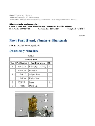
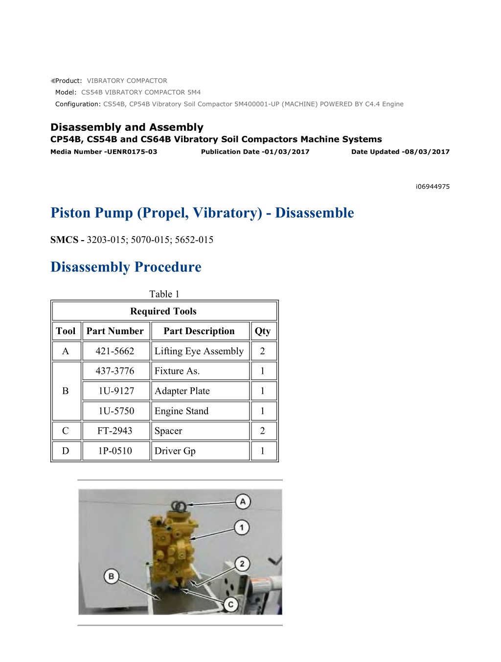
CS54B, CP54B Vibratory Soil Compactor 5M400001-UP (MACHINE) POWERED B... 1/22 Product: VIBRATORY COMPACTOR Model: CS54B VIBRATORY COMPACTOR 5M4 Configuration: CS54B, CP54B Vibratory Soil Compactor 5M400001-UP (MACHINE) POWERED BY C4.4 Engine Disassembly and Assembly CP54B, CS54B and CS64B Vibratory Soil Compactors Machine Systems Media Number -UENR0175-03 Publication Date -01/03/2017 Date Updated -08/03/2017 i06944975 Piston Pump (Propel, Vibratory) - Disassemble SMCS - 3203-015; 5070-015; 5652-015 Disassembly Procedure Table 1 Required Tools Tool Part Number Part Description Qty A 421-5662 Lifting Eye Assembly 2 437-3776 Fixture As. 1 B 1U-9127 Adapter Plate 1 1U-5750 Engine Stand 1 C FT-2943 Spacer 2 D 1P-0510 Driver Gp 1 https://127.0.0.1/sisweb/sisweb/techdoc/techdoc_print_page.jsp?returnurl=/sis... 2022/6/19
CS54B, CP54B Vibratory Soil Compactor 5M400001-UP (MACHINE) POWERED B... 2/22 Illustration 1 g06181528 Personal injury can result from being struck by parts propelled by a released spring force. Make sure to wear all necessary protective equipment. Follow the recommended procedure and use all recommended tooling to release the spring force. 1. Use Tooling (C) to attach the piston pump to Tooling (A) or a suitable fixture. 2. Remove bolts (2). Use Tooling (A) and a suitable lifting device to remove housing (1). The weight of housing (1) is approximately 51 kg (114 lb). Illustration 2 g06181580 3. Remove control plate (3) from housing (1). Illustration 3 g06181594 https://127.0.0.1/sisweb/sisweb/techdoc/techdoc_print_page.jsp?returnurl=/sis... 2022/6/19
CS54B, CP54B Vibratory Soil Compactor 5M400001-UP (MACHINE) POWERED B... 3/22 4. Remove rotating group (4). Illustration 4 g06181629 5. Remove piston assemblies (5) and retainer plate (6) from barrel (7). Illustration 5 g06181632 6. Remove bearing (8) from barrel (7). Illustration 6 g06181637 https://127.0.0.1/sisweb/sisweb/techdoc/techdoc_print_page.jsp?returnurl=/sis... 2022/6/19
https://www.ebooklibonline.com Hello dear friend! Thank you very much for reading. Enter the link into your browser. The full manual is available for immediate download. https://www.ebooklibonline.com
CS54B, CP54B Vibratory Soil Compactor 5M400001-UP (MACHINE) POWERED B... 4/22 Personal injury can result from being struck by parts propelled by a released spring force. Make sure to wear all necessary protective equipment. Follow the recommended procedure and use all recommended tooling to release the spring force. 7. Use tooling (D) and a suitable press to remove retaining ring (9) from barrel (7). Illustration 7 g06181655 8. Remove spring (10), washer (11), and pins (12) from barrel (7). Illustration 8 g06181659 9. Remove swashplate assembly (13) from flange (14). https://127.0.0.1/sisweb/sisweb/techdoc/techdoc_print_page.jsp?returnurl=/sis... 2022/6/19
CS54B, CP54B Vibratory Soil Compactor 5M400001-UP (MACHINE) POWERED B... 5/22 Illustration 9 g06181665 10. Remove bearings (15) and slide (16) from swashplate (13). Note the orientation of slide (16) for assembly purposes. Illustration 10 g06181668 11. Remove bearing races (17) from flange (14). Illustration 11 g06181673 12. Remove retaining ring (18) and lip seal (19) from flange (14). https://127.0.0.1/sisweb/sisweb/techdoc/techdoc_print_page.jsp?returnurl=/sis... 2022/6/19
CS54B, CP54B Vibratory Soil Compactor 5M400001-UP (MACHINE) POWERED B... 6/22 Illustration 12 g06181677 13. Remove retaining ring (20) from flange (14). Illustration 13 g06181679 14. Remove O-ring seal (22). Use a soft faced hammer to remove shaft assembly (21) from flange (14). Illustration 14 g06181681 15. Remove retaining ring (23) from shaft (21). https://127.0.0.1/sisweb/sisweb/techdoc/techdoc_print_page.jsp?returnurl=/sis... 2022/6/19
CS54B, CP54B Vibratory Soil Compactor 5M400001-UP (MACHINE) POWERED B... 7/22 Illustration 15 g06181685 16. Use a suitable press to remove bearing (24) from shaft (21). Illustration 16 g06181986 17. Remove bolts (25). Illustration 17 g06181990 https://127.0.0.1/sisweb/sisweb/techdoc/techdoc_print_page.jsp?returnurl=/sis... 2022/6/19
CS54B, CP54B Vibratory Soil Compactor 5M400001-UP (MACHINE) POWERED B... 8/22 Personal injury can result from being struck by parts propelled by a released spring force. Make sure to wear all necessary protective equipment. Follow the recommended procedure and use all recommended tooling to release the spring force. 18. Use Tooling (A) and a suitable lifting device to remove housing (1). The weight of housing (1) is approximately 40 kg (89 lb). Illustration 18 g06181998 19. Remove control plate (26). Illustration 19 g06182004 20. Remove rotating group (27). https://127.0.0.1/sisweb/sisweb/techdoc/techdoc_print_page.jsp?returnurl=/sis... 2022/6/19
CS54B, CP54B Vibratory Soil Compactor 5M400001-UP (MACHINE) POWERED B... 9/22 Illustration 20 g06182009 21. Remove piston assemblies (28) and retainer plate (29) from barrel (30). Illustration 21 g06182020 22. Remove bearing (31) from barrel (30). Illustration 22 g06182023 https://127.0.0.1/sisweb/sisweb/techdoc/techdoc_print_page.jsp?returnurl=/sis... 2022/6/19
CS54B, CP54B Vibratory Soil Compactor 5M400001-UP (MACHINE) POWERED... 10/22 Personal injury can result from being struck by parts propelled by a released spring force. Make sure to wear all necessary protective equipment. Follow the recommended procedure and use all recommended tooling to release the spring force. 23. Use tooling (D) and a suitable press to remove retaining ring (32) from barrel (30). Illustration 23 g06182025 24. Remove spring (33), washer (34), and pins (35) from barrel (30). Illustration 24 g06182031 25. Remove swashplate assembly (36) from flange (37). https://127.0.0.1/sisweb/sisweb/techdoc/techdoc_print_page.jsp?returnurl=/sis... 2022/6/19
CS54B, CP54B Vibratory Soil Compactor 5M400001-UP (MACHINE) POWERED... 11/22 Illustration 25 g06182032 26. Remove bearings (38) and slide (39) from swashplate (36). Note the orientation of slide (39) for assembly purposes. Illustration 26 g06182043 27. Remove bearing races (40) from flange (37). Illustration 27 g06182054 28. Remove retaining ring (41) from flange (37). https://127.0.0.1/sisweb/sisweb/techdoc/techdoc_print_page.jsp?returnurl=/sis... 2022/6/19
CS54B, CP54B Vibratory Soil Compactor 5M400001-UP (MACHINE) POWERED... 12/22 Illustration 28 g06182061 29. Remove O-ring seal (43). Use a soft faced hammer to remove shaft assembly (42) from flange (37). Illustration 29 g06182077 30. Remove retaining ring (44) from shaft (42). Illustration 30 g06182080 31. Use a suitable press to remove bearing (45) from shaft (42). https://127.0.0.1/sisweb/sisweb/techdoc/techdoc_print_page.jsp?returnurl=/sis... 2022/6/19
CS54B, CP54B Vibratory Soil Compactor 5M400001-UP (MACHINE) POWERED... 13/22 Illustration 31 g06182207 32. Remove bolts (47), valve group (46), and the gasket from housing (1). Illustration 32 g06182105 Personal injury can result from being struck by parts propelled by a released spring force. Make sure to wear all necessary protective equipment. Follow the recommended procedure and use all recommended tooling to release the spring force. 33. Remove screw lock (48) from valve group (46). https://127.0.0.1/sisweb/sisweb/techdoc/techdoc_print_page.jsp?returnurl=/sis... 2022/6/19
CS54B, CP54B Vibratory Soil Compactor 5M400001-UP (MACHINE) POWERED... 14/22 Illustration 33 g06182180 34. Remove O-ring seal (51) from screw lock (48). remove spring (50) and retainer (49) from valve group (46). Illustration 34 g06182187 35. Remove bolts (52) and piston (53). Remove bolt (54), retainer (55), and pin (56) from valve group (46). Illustration 35 g06182190 36. Remove O-ring seals (57) and shim (58) from piston (53). https://127.0.0.1/sisweb/sisweb/techdoc/techdoc_print_page.jsp?returnurl=/sis... 2022/6/19
CS54B, CP54B Vibratory Soil Compactor 5M400001-UP (MACHINE) POWERED... 15/22 Illustration 36 g06182194 37. Remove O-ring seal (59) from pin (56). Illustration 37 g06182197 38. Remove bolts (60), valve group (61), and the gasket from housing (1). Illustration 38 g06182203 https://127.0.0.1/sisweb/sisweb/techdoc/techdoc_print_page.jsp?returnurl=/sis... 2022/6/19
CS54B, CP54B Vibratory Soil Compactor 5M400001-UP (MACHINE) POWERED... 16/22 Personal injury can result from being struck by parts propelled by a released spring force. Make sure to wear all necessary protective equipment. Follow the recommended procedure and use all recommended tooling to release the spring force. 39. Remove switch (62) from valve group (61). Illustration 39 g06182240 40. Remove pin (65), spring (64), and retainer (63) from valve group (61). Illustration 40 g06183892 41. Remove bolts (66) and piston (67). Remove bolt (68), retainer (69), and pin (70) from valve group (61). https://127.0.0.1/sisweb/sisweb/techdoc/techdoc_print_page.jsp?returnurl=/sis... 2022/6/19
CS54B, CP54B Vibratory Soil Compactor 5M400001-UP (MACHINE) POWERED... 17/22 Illustration 41 g06183897 42. Remove O-ring seals (71) and shim (72) from piston (67). Illustration 42 g06183901 43. Remove O-ring seal (73) from pin (70). Illustration 43 g06183903 https://127.0.0.1/sisweb/sisweb/techdoc/techdoc_print_page.jsp?returnurl=/sis... 2022/6/19
CS54B, CP54B Vibratory Soil Compactor 5M400001-UP (MACHINE) POWERED... 18/22 Illustration 44 g06183909 Personal injury can result from being struck by parts propelled by a released spring force. Make sure to wear all necessary protective equipment. Follow the recommended procedure and use all recommended tooling to release the spring force. 44. Remove nut (74), the O-ring seal, and coil (75). 45. Remove cartridge (76). Illustration 45 g06183911 46. Remove O-ring seal (77) from cartridge (76). Remove spool (78) and spring (79), https://127.0.0.1/sisweb/sisweb/techdoc/techdoc_print_page.jsp?returnurl=/sis... 2022/6/19
CS54B, CP54B Vibratory Soil Compactor 5M400001-UP (MACHINE) POWERED... 19/22 Illustration 46 g06183913 Personal injury can result from being struck by parts propelled by a released spring force. Make sure to wear all necessary protective equipment. Follow the recommended procedure and use all recommended tooling to release the spring force. 47. Remove plug (80). Illustration 47 g06183916 48. Remove back up ring (81), O-ring seal (82), spring (83), and valve assembly (84) from plug (80). Repeat for the other valve assemblies. https://127.0.0.1/sisweb/sisweb/techdoc/techdoc_print_page.jsp?returnurl=/sis... 2022/6/19
Suggest: For more complete manuals. Please go to the home page. https://www.ebooklibonline.com If the above button click is invalid. Please download this document first, and then click the above link to download the complete manual. Thank you so much for reading
CS54B, CP54B Vibratory Soil Compactor 5M400001-UP (MACHINE) POWERED... 20/22 Illustration 48 g06183919 Personal injury can result from being struck by parts propelled by a released spring force. Make sure to wear all necessary protective equipment. Follow the recommended procedure and use all recommended tooling to release the spring force. 49. Remove valve (85). Illustration 49 g06183922 50. Remove O-ring seal (86), guide (87), shims (88), and spring (89) from valve (85). https://127.0.0.1/sisweb/sisweb/techdoc/techdoc_print_page.jsp?returnurl=/sis... 2022/6/19
CS54B, CP54B Vibratory Soil Compactor 5M400001-UP (MACHINE) POWERED... 21/22 Illustration 50 g06183926 Illustration 51 g06183928 51. Remove bolts (90), cartridge group (91), and the O-ring seals. Remove ring guides (92). Repeat for the other cartridge group. Illustration 52 g06183929 52. Remove bearings (93) and coupler (94). https://127.0.0.1/sisweb/sisweb/techdoc/techdoc_print_page.jsp?returnurl=/sis... 2022/6/19
https://www.ebooklibonline.com Hello dear friend! Thank you very much for reading. Enter the link into your browser. The full manual is available for immediate download. https://www.ebooklibonline.com

