Caterpillar Cat 966G II Wheel Loader (Prefix AWY) Service Repair Manual Instant Download (AWY00001 and up)
Please open the website below to get the complete manualnn//
Download Presentation

Please find below an Image/Link to download the presentation.
The content on the website is provided AS IS for your information and personal use only. It may not be sold, licensed, or shared on other websites without obtaining consent from the author. Download presentation by click this link. If you encounter any issues during the download, it is possible that the publisher has removed the file from their server.
E N D
Presentation Transcript
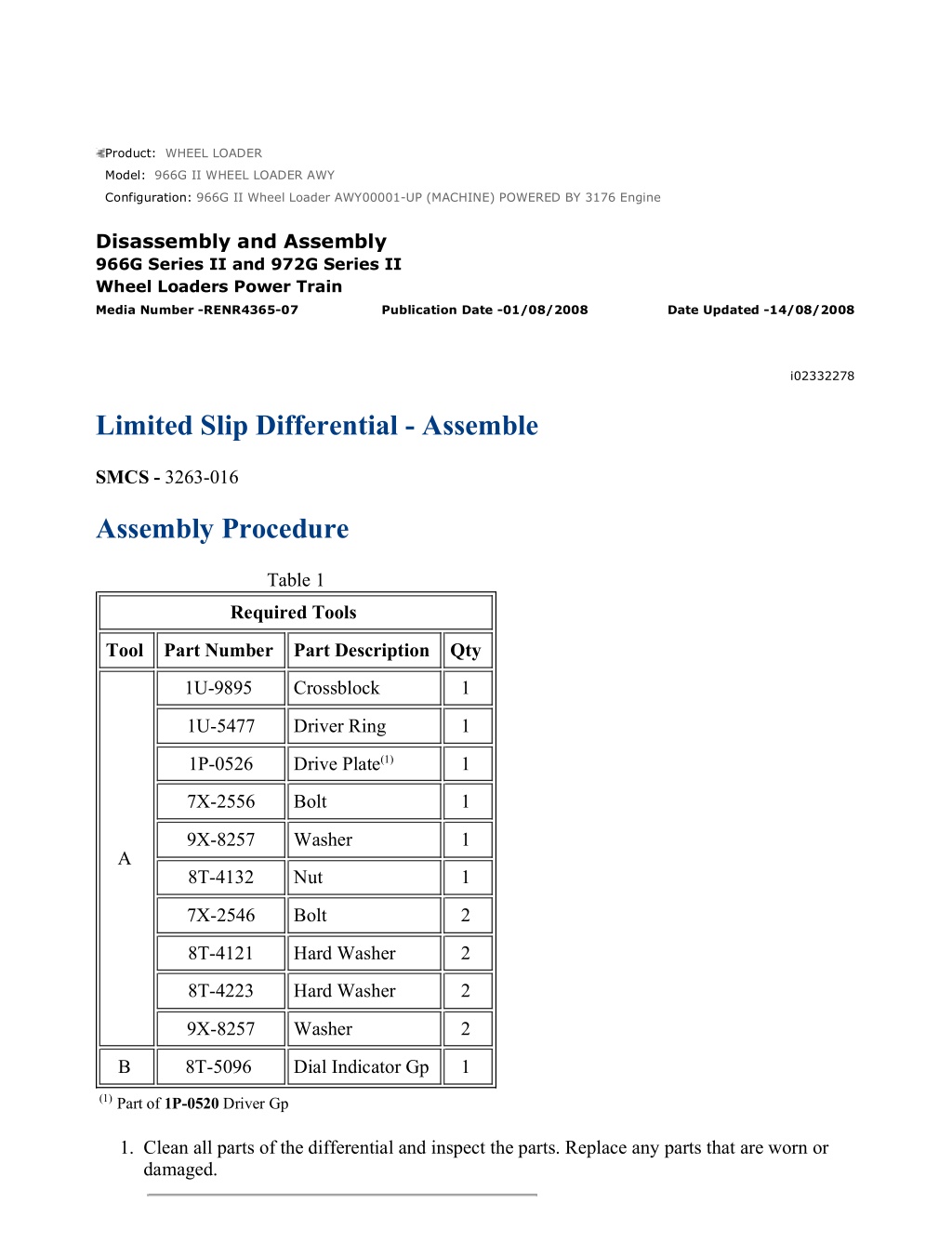
966G II Wheel Loader AWY00001-UP (MACHINE) POWERED BY 3176 Engine(S... 1/10 Product: WHEEL LOADER Model: 966G II WHEEL LOADER AWY Configuration: 966G II Wheel Loader AWY00001-UP (MACHINE) POWERED BY 3176 Engine Disassembly and Assembly 966G Series II and 972G Series II Wheel Loaders Power Train Media Number -RENR4365-07 Publication Date -01/08/2008 Date Updated -14/08/2008 i02332278 Limited Slip Differential - Assemble SMCS - 3263-016 Assembly Procedure Table 1 Required Tools Tool Part Number Part Description Qty 1U-9895 Crossblock 1 1U-5477 Driver Ring 1 Drive Plate(1) 1P-0526 1 7X-2556 Bolt 1 9X-8257 Washer 1 A 8T-4132 Nut 1 7X-2546 Bolt 2 8T-4121 Hard Washer 2 8T-4223 Hard Washer 2 9X-8257 Washer 2 B 8T-5096 Dial Indicator Gp 1 (1)Part of 1P-0520 Driver Gp 1. Clean all parts of the differential and inspect the parts. Replace any parts that are worn or damaged. https://127.0.0.1/sisweb/sisweb/techdoc/techdoc_print_page.jsp?returnurl=/sis... 2022/3/27
966G II Wheel Loader AWY00001-UP (MACHINE) POWERED BY 3176 Engine(S... 2/10 Illustration 1 g00333101 2. Install thrust washer (18). Apply clean axle oil to the face of the thrust washer. Illustration 2 g00333298 Note: Replace the disc pack if the stack heights of the two disc packs are not symmetrical within 0.10 mm (0.004 inch). Also replace the disc pack if the friction material is worn and areas of the friction discs are allowing steel to contact steel. Make sure that the correct disc packs are used for replacement according to the description on the differential case cover. If "THIN" is marked on the cover, use two thin disc packs. If "THICK" is marked on the cover, use two thick disc packs. Do not use one disc of each size. Illustration 3 g00342357 https://127.0.0.1/sisweb/sisweb/techdoc/techdoc_print_page.jsp?returnurl=/sis... 2022/3/27
966G II Wheel Loader AWY00001-UP (MACHINE) POWERED BY 3176 Engine(S... 3/10 Illustration 4 g00333100 3. Thoroughly apply clean axle oil on the plates and on the friction discs. Install two friction discs (16) and two plates (17) in the case housing in alternating order. Start with a plate. Illustration 5 g00342353 Illustration 6 g00342352 4. Align the tabs on actuator housing (15) with the slots in the case housing. Install actuator housing (15) in the case housing. https://127.0.0.1/sisweb/sisweb/techdoc/techdoc_print_page.jsp?returnurl=/sis... 2022/3/27
https://www.ebooklibonline.com Hello dear friend! Thank you very much for reading. Enter the link into your browser. The full manual is available for immediate download. https://www.ebooklibonline.com
966G II Wheel Loader AWY00001-UP (MACHINE) POWERED BY 3176 Engine(S... 4/10 Illustration 7 g00333078 5. Install gear (14) in the case housing. Turn the gear slowly until the spline engages with the teeth of two friction discs (16). Make sure that the gear is completely seated. Illustration 8 g00333022 6. Install pinion gears (10) on pinion shaft (11). Repeat this step for pinion gears (12) on pinion shaft (13). Thoroughly apply clean axle oil on the pinion shafts and on the pinion gears. Illustration 9 g00333021 https://127.0.0.1/sisweb/sisweb/techdoc/techdoc_print_page.jsp?returnurl=/sis... 2022/3/27
966G II Wheel Loader AWY00001-UP (MACHINE) POWERED BY 3176 Engine(S... 5/10 7. Install pinion shaft (13) and two pinion gears (12) as a unit. Rotate the pinion gears slightly until the pinion shaft is resting in the slots in the actuator housing. Illustration 10 g00333020 8. Install pinion shaft (11) and two pinion gears (10) as a unit. Illustration 11 g00333358 9. Assemble gear (9) and actuator housing (8), as shown. Illustration 12 g00332965 https://127.0.0.1/sisweb/sisweb/techdoc/techdoc_print_page.jsp?returnurl=/sis... 2022/3/27
966G II Wheel Loader AWY00001-UP (MACHINE) POWERED BY 3176 Engine(S... 6/10 10. Align the tabs on actuator housing (8) with the slots in the case housing. Install actuator housing (8) and gear (9) in the case housing. Illustration 13 g00333298 Note: Replace the disc pack if the stack heights of the two disc packs are not symmetrical within 0.10 mm (0.004 inch). Also replace the disc pack if the friction material is worn and areas of the friction discs are allowing steel to contact steel. Make sure that the correct disc packs are used for replacement according to the description on the differential case cover. If "THIN" is marked on the cover, use two thin disc packs. If "THICK" is marked on the cover, use two thick disc packs. Do not use one disc of each size. Illustration 14 g00342292 https://127.0.0.1/sisweb/sisweb/techdoc/techdoc_print_page.jsp?returnurl=/sis... 2022/3/27
966G II Wheel Loader AWY00001-UP (MACHINE) POWERED BY 3176 Engine(S... 7/10 Illustration 15 g00332963 11. Thoroughly apply clean axle oil on the plates and on the friction discs. Install two friction discs (6) and two plates (7) in the case housing in alternating order. Start with a friction disc. 12. Use the following procedure to measure the end play gap: Illustration 16 g00332921 a. Install Tooling (A) on case housing (3), as shown. Note: The center bolt of Tooling (A) must have a M16 2.0 thread in order to apply the proper preload on the disc packs. Illustration 17 g00332959 b. Tighten the center bolt of Tooling (A) to a torque of 27 N m (20 lb ft). This will apply 900 kg (2000 lb) of preload on the disc packs. https://127.0.0.1/sisweb/sisweb/techdoc/techdoc_print_page.jsp?returnurl=/sis... 2022/3/27
966G II Wheel Loader AWY00001-UP (MACHINE) POWERED BY 3176 Engine(S... 8/10 Illustration 18 g00332922 c. Mount the magnetic base of Tooling (B) on the inner face of differential case cover (2), as shown. d. Zero the dial indicator on the outer face of differential case cover (2), as shown. e. Carefully remove Tooling (B) from differential case cover (2). Illustration 19 g00332962 f. Mount the magnetic base of Tooling (B) on the top of case housing (3), as shown. g. Place the dial indicator on disc pack (5), as shown. Record the reading. h. Record two additional readings from different areas of disc pack (5). i. Average the three readings. This is the end play gap. j. If the end play gap for the existing disc packs is greater than 0.81 mm (0.032 inch), the disc packs must be replaced. If the end play gap for the existing disc packs is correct, proceed to Step 14. 13. If new disc packs are installed, the end play gap must be between 0.203 mm (0.008 inch) and 0.508 mm (0.020 inch). Measure the end play gap again. https://127.0.0.1/sisweb/sisweb/techdoc/techdoc_print_page.jsp?returnurl=/sis... 2022/3/27
966G II Wheel Loader AWY00001-UP (MACHINE) POWERED BY 3176 Engine(S... 9/10 a. If the end play gap is not between 0.203 mm (0.008 inch) and 0.508 mm (0.020 inch) and two thin disc packs were installed, replace the thin disc packs with thick disc packs and measure the end play gap again. b. If the end play gap is not yet between 0.203 mm (0.008 inch) and 0.508 mm (0.020 inch), replace the pinion shafts and/or both actuator housings. Use either two thin disc packs or two thick disc packs in order to achieve an end play gap that is between 0.203 mm (0.008 inch) and 0.508 mm (0.020 inch). Note: If a different size of disc packs was installed, change the existing description on the differential case cover for future reference. Illustration 20 g00332919 14. Apply a small amount of grease on the back side of thrust washer (4). This will retain the thrust washer during installation of the differential case cover. Turn differential case cover (2) upside-down and install thrust washer (4). NOTICE A new differential group or a new case assembly will be equipped with bolts that are used for shipping , assembly, and and storage purposes only. Remove and discard these bolts after the bevel gear has been installed. These bolts should not be used for final assembly. https://127.0.0.1/sisweb/sisweb/techdoc/techdoc_print_page.jsp?returnurl=/sis... 2022/3/27
966G II Wheel Loader AWY00001-UP (MACHINE) POWERED BY 3176 Engine(... 10/10 Illustration 21 g00332918 Illustration 22 g00333618 15. Install differential case cover (2) on case housing (3). Align the marks on the differential case cover with the marks on the case housing. 16. Install bolts (1). Tighten the bolts to a torque of 61 7 N m (45 5 lb ft). Bolts (1) are used to hold the differential case together until final assembly. Remove bolts (1) and discard bolts (1) after the bevel gear has been installed. End By: a. Install the differential and the bevel gear. Refer to Disassembly and Assembly, "Differential and Bevel Gear - Install". https://127.0.0.1/sisweb/sisweb/techdoc/techdoc_print_page.jsp?returnurl=/sis... 2022/3/27
966G II Wheel Loader AWY00001-UP (MACHINE) POWERED BY 3176 Engine(S... 1/3 Product: WHEEL LOADER Model: 966G II WHEEL LOADER AWY Configuration: 966G II Wheel Loader AWY00001-UP (MACHINE) POWERED BY 3176 Engine Disassembly and Assembly 966G Series II and 972G Series II Wheel Loaders Power Train Media Number -RENR4365-07 Publication Date -01/08/2008 Date Updated -14/08/2008 i02710529 NoSPIN Differential - Disassemble SMCS - 3265-015 Disassembly Procedure Start By: a. Disassemble the differential and the bevel gear. Refer to Disassembly and Assembly, "Differential and Bevel Gear - Disassemble". 1. Put alignment marks on both halves of the differential case. NOTICE A new differential group or a new case assembly will be equipped with four bolts and washers that are used for shipping, assembly, and storage purposes only. Remove and discard these four bolts and washers after the bevel gear has been installed. These four bolts and washers should not be used for final assembly. https://127.0.0.1/sisweb/sisweb/techdoc/techdoc_print_page.jsp?returnurl=/sis... 2022/3/27
966G II Wheel Loader AWY00001-UP (MACHINE) POWERED BY 3176 Engine(S... 2/3 Illustration 1 g00333763 Parts under spring force can cause personal injury. When the bolts are removed, the spring force against the differential case will be released. To avoid personal injury, put the differential in a press before the bolts are removed in order to retain the case half. 2. Put the differential in a suitable press and remove bolts (1) and the washers. Slowly release the spring compression. 3. Remove top half (2) of the differential case. Illustration 2 g01360343 4. Remove side gear (3), spring (4), retainer (5), and clutch assembly (6). https://127.0.0.1/sisweb/sisweb/techdoc/techdoc_print_page.jsp?returnurl=/sis... 2022/3/27
966G II Wheel Loader AWY00001-UP (MACHINE) POWERED BY 3176 Engine(S... 3/3 Illustration 3 g01365551 5. Remove spider assembly (7), clutch assembly (8), retainer (9), spring (10), and side gear (11). https://127.0.0.1/sisweb/sisweb/techdoc/techdoc_print_page.jsp?returnurl=/sis... 2022/3/27
966G II Wheel Loader AWY00001-UP (MACHINE) POWERED BY 3176 Engine(S... 1/4 Product: WHEEL LOADER Model: 966G II WHEEL LOADER AWY Configuration: 966G II Wheel Loader AWY00001-UP (MACHINE) POWERED BY 3176 Engine Disassembly and Assembly 966G Series II and 972G Series II Wheel Loaders Power Train Media Number -RENR4365-07 Publication Date -01/08/2008 Date Updated -14/08/2008 i02326458 NoSPIN Differential - Assemble SMCS - 3265-016 Assembly Procedure 1. Put the bottom half of the differential case in a suitable press. https://127.0.0.1/sisweb/sisweb/techdoc/techdoc_print_page.jsp?returnurl=/sis... 2022/3/27
966G II Wheel Loader AWY00001-UP (MACHINE) POWERED BY 3176 Engine(S... 2/4 Illustration 1 g01111787 Personal injury can result from being struck by parts propelled by a released spring force. Make sure to wear all necessary protective equipment. Follow the recommended procedure and use all recommended tooling to release the spring force. 2. Install side gear (10), retainer (9), spring (8), clutch assembly (12), and spider assembly (11) . Illustration 2 g01111776 https://127.0.0.1/sisweb/sisweb/techdoc/techdoc_print_page.jsp?returnurl=/sis... 2022/3/27
966G II Wheel Loader AWY00001-UP (MACHINE) POWERED BY 3176 Engine(S... 3/4 Personal injury can result from being struck by parts propelled by a released spring force. Make sure to wear all necessary protective equipment. Follow the recommended procedure and use all recommended tooling to release the spring force. 3. Install clutch assembly (4), spring (3), retainer (7), spacer block (6), and side gear (5) . Illustration 3 g00333763 Personal injury can result from being struck by parts propelled by a released spring force. Make sure to wear all necessary protective equipment. Follow the recommended procedure and use all recommended tooling to release the spring force. 4. Install top half (2) of the differential case. Use the press to compress the spring in the differential. 5. Install bolts (1) that hold the two halves of the differential case together. End By: Install the differential and the bevel gear. Refer to Disassembly and Assembly, "Differential and Bevel Gear - Install". https://127.0.0.1/sisweb/sisweb/techdoc/techdoc_print_page.jsp?returnurl=/sis... 2022/3/27
966G II Wheel Loader AWY00001-UP (MACHINE) POWERED BY 3176 Engine(S... 1/4 Product: WHEEL LOADER Model: 966G II WHEEL LOADER AWY Configuration: 966G II Wheel Loader AWY00001-UP (MACHINE) POWERED BY 3176 Engine Disassembly and Assembly 966G Series II and 972G Series II Wheel Loaders Power Train Media Number -RENR4365-07 Publication Date -01/08/2008 Date Updated -14/08/2008 i01630247 Oscillating Axle (Rear) - Install SMCS - 3278-012-RE Installation Procedure Note: Make sure that all mounting surfaces are clean prior to installation. Illustration 1 g00304904 Typical Example 1. Fasten a suitable retainer around the axle, around front axle support (5) and around yoke (6). This will prevent the front axle support and the yoke from falling as the oscillating axle is being installed. https://127.0.0.1/sisweb/sisweb/techdoc/techdoc_print_page.jsp?returnurl=/sis... 2022/3/27
Suggest: For more complete manuals. Please go to the home page. https://www.ebooklibonline.com If the above button click is invalid. Please download this document first, and then click the above link to download the complete manual. Thank you so much for reading
966G II Wheel Loader AWY00001-UP (MACHINE) POWERED BY 3176 Engine(S... 2/4 Illustration 2 g00449363 2. Attach a suitable lifting sling to each side of the oscillating axle, as shown. Attach a suitable hoist to both lifting slings. Raise the oscillating axle into position. The weight of the oscillating axle is 1635 kg (3600 lb). Illustration 3 g00449372 3. Install nuts (9) that hold front axle support (10) to the machine frame. The torque for nuts (9) is 1000 125 N m (740 90 lb ft). https://127.0.0.1/sisweb/sisweb/techdoc/techdoc_print_page.jsp?returnurl=/sis... 2022/3/27
966G II Wheel Loader AWY00001-UP (MACHINE) POWERED BY 3176 Engine(S... 3/4 Illustration 4 g00449371 4. Install four nuts (7) that hold rear axle support (8) to the machine frame. The torque for nuts (7) is 1000 125 N m (740 90 lb ft). 5. Remove the lifting slings from both sides of the oscillating axle. Remove the retainer which holds the front axle support in place. Illustration 5 g00449358 6. Connect two hose assemblies (4) to the oscillating axle. Illustration 6 g00448970 7. Connect hose assembly (3) to the oscillating axle. 8. Connect two grease tubes (2) to the oscillating axle. https://127.0.0.1/sisweb/sisweb/techdoc/techdoc_print_page.jsp?returnurl=/sis... 2022/3/27
https://www.ebooklibonline.com Hello dear friend! Thank you very much for reading. Enter the link into your browser. The full manual is available for immediate download. https://www.ebooklibonline.com

