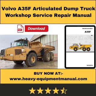
Caterpillar Cat 740 Ejector Articulated Truck (Prefix B1R) Service Repair Manual Instant Download
Please open the website below to get the complete manualnn//
Download Presentation

Please find below an Image/Link to download the presentation.
The content on the website is provided AS IS for your information and personal use only. It may not be sold, licensed, or shared on other websites without obtaining consent from the author. Download presentation by click this link. If you encounter any issues during the download, it is possible that the publisher has removed the file from their server.
E N D
Presentation Transcript
Service Repair Manual Models 740Ejector ArticulatedTruck
740 Ejector Articulated Truck B1R00001-UP (MACHINE) POWERED BY C15 Engi... 1/6 Shutdown SIS Previous Screen Product: EJECTOR TRUCK Model: 740 EJECTOR TRUCK B1R Configuration: 740 Ejector Articulated Truck B1R00001-UP (MACHINE) POWERED BY C15 Engine Disassembly and Assembly 730 EJECTOR and 740 EJECTOR Articulated Trucks Media Number -RENR5176-07 Publication Date -01/04/2018 Date Updated -13/04/2018 i02381152 Ejector Blade Floor Rollers - Assemble SMCS - 6229-016 S/N - AZZ1-UP S/N - B1R1-UP Assembly Procedure Table 1 Required Tools Tools Part Number Part Description Qty B 1P-0510 Driver Group 1 C 7X-7699 Grease 1 1. Clean all parts and inspect all parts. If any parts are worn or damaged, use new Caterpillar parts for replacement. Illustration 1 g01188833 https://127.0.0.1/sisweb/sisweb/techdoc/techdoc_print_page.jsp?returnurl=/sis... 2020/1/18
740 Ejector Articulated Truck B1R00001-UP (MACHINE) POWERED BY C15 Engi... 2/6 2. Use Tooling (B) in order to install lip seal (13) into housing (11). Illustration 2 g01195296 3. Apply Tooling (C) to lip seal (13) on housing (11) before installing the housing onto bracket (3). Illustration 3 g01188834 4. Install bearing race (12) onto the floor roller with the shoulder on the bearing race toward bracket (3). Illustration 4 g01188835 https://127.0.0.1/sisweb/sisweb/techdoc/techdoc_print_page.jsp?returnurl=/sis... 2020/1/18
https://www.ebooklibonline.com Hello dear friend! Thank you very much for reading. Enter the link into your browser. The full manual is available for immediate download. https://www.ebooklibonline.com
740 Ejector Articulated Truck B1R00001-UP (MACHINE) POWERED BY C15 Engi... 3/6 5. Apply Tooling (C) to the bearing cavity between bearing race (12) and housing (11). Illustration 5 g00896615 6. Install roller bearing (9). Illustration 6 g01195297 7. Install O-ring seal (7) onto housing (11) and roller bearing (9). Illustration 7 g01188836 8. Apply Tooling (C) to roller bearing (9). https://127.0.0.1/sisweb/sisweb/techdoc/techdoc_print_page.jsp?returnurl=/sis... 2020/1/18
740 Ejector Articulated Truck B1R00001-UP (MACHINE) POWERED BY C15 Engi... 4/6 Illustration 8 g00896631 9. Install inner plate (8) onto roller bearing (9). Illustration 9 g00926131 10. Install O-ring seal (6) onto bracket (3). Illustration 10 g00926132 11. Install cap (2) onto bracket (3) before securing the cap in place with bolt (1). https://127.0.0.1/sisweb/sisweb/techdoc/techdoc_print_page.jsp?returnurl=/sis... 2020/1/18
740 Ejector Articulated Truck B1R00001-UP (MACHINE) POWERED BY C15 Engi... 5/6 Illustration 11 g01188837 12. Use Tooling (B) to install lip seal (10) into bottom wheel (5). Illustration 12 g00926133 13. Apply Tooling (C) to lip seal (10) on bottom wheel (5) before positioning the bottom wheel to housing (11). Install three bolts (4) and the washers. Tighten the bolts in equal amounts in order to pull the bottom wheel onto the housing. Illustration 13 g00896633 14. Install remaining bolts (4) and the washers in order to secure bottom wheel (5) to housing (11). https://127.0.0.1/sisweb/sisweb/techdoc/techdoc_print_page.jsp?returnurl=/sis... 2020/1/18
740 Ejector Articulated Truck B1R00001-UP (MACHINE) POWERED BY C15 Engi... 6/6 Illustration 14 g00926134 15. Repeat Step 2 through 14 in order to install the wheel on the opposite side of bracket (3). End By: a. Install the ejector blade floor roller onto the machine. Refer to Disassembly and Assembly Manual, "Ejector Blade Floor Rollers - Install". Copyright 1993 - 2020 Caterpillar Inc. Sat Jan 18 17:21:02 UTC+0800 2020 All Rights Reserved. Private Network For SIS Licensees. https://127.0.0.1/sisweb/sisweb/techdoc/techdoc_print_page.jsp?returnurl=/sis... 2020/1/18
740 Ejector Articulated Truck B1R00001-UP (MACHINE) POWERED BY C15 Engi... 1/4 Shutdown SIS Previous Screen Product: EJECTOR TRUCK Model: 740 EJECTOR TRUCK B1R Configuration: 740 Ejector Articulated Truck B1R00001-UP (MACHINE) POWERED BY C15 Engine Disassembly and Assembly 730 EJECTOR and 740 EJECTOR Articulated Trucks Media Number -RENR5176-07 Publication Date -01/04/2018 Date Updated -13/04/2018 i02386576 Ejector Blade Floor Rollers - Install SMCS - 6229-012 S/N - AZZ1-UP S/N - B1R1-UP Installation Procedure Note: Cleanliness is an important factor. Before the installation procedure, the exterior of the component should be thoroughly cleaned. This will help to prevent dirt from entering the internal mechanism. Illustration 1 g01191143 1. Use two people in order to install ejector roller (3) onto both ends of reaction plate (7). The weight of one ejector roller (3) is approximately 27 kg (60 lb). Install block (11) onto both ends of reaction plate (7). https://127.0.0.1/sisweb/sisweb/techdoc/techdoc_print_page.jsp?returnurl=/sis... 2020/1/18
740 Ejector Articulated Truck B1R00001-UP (MACHINE) POWERED BY C15 Engi... 2/4 Illustration 2 g01191144 2. Install bolts (10) onto both ends of the reaction plate (7). Illustration 3 g01191145 3. Install adapter plate (8) and install bolts (9) onto both ends of reaction plate (7). Illustration 4 g01191121 4. Use a suitable lifting device in order to install the assembly of ejector rollers (3) and reaction plate (7) onto the machine. The weight of the assembly is approximately 90 kg (200 lb). https://127.0.0.1/sisweb/sisweb/techdoc/techdoc_print_page.jsp?returnurl=/sis... 2020/1/18
740 Ejector Articulated Truck B1R00001-UP (MACHINE) POWERED BY C15 Engi... 3/4 5. Install shims (6). Use the correct shims that were noted during the removal procedure. Carefully push the assembly of ejector rollers (3) and reaction plate (7) and shims (6) under the ejector blade. Illustration 5 g01191146 6. Install shims (5). Use the shims that were noted during the removal procedure. Install bolts (4). Illustration 6 g01191118 7. Turn bolts (1) on both sides of the ejector blade equally in order to lower ejector rollers (3) onto the truck body. Continue turning bolts (1) until bolts (1) are clear of the surface of the truck body. Use a feeler gauge in order to verify that ejector rollers (3) are in contact with the truck body. 8. Tighten nut (2) on bolt (1) in order to prevent bolt (1) from rotating. Repeat Step 7 and Step 8 for bolt (1) on the opposite end of the ejector blade. 9. Turn the disconnect switch to the ON position. Start the engine and completely retract the ejector. Shut off the engine. 10. Check and adjust the clearance of the ejector blade. Refer to Operation and Maintenance Manual, "Ejector Blade Alignment - Check/Adjust". Copyright 1993 - 2020 Caterpillar Inc. Sat Jan 18 17:21:58 UTC+0800 2020 All Rights Reserved. https://127.0.0.1/sisweb/sisweb/techdoc/techdoc_print_page.jsp?returnurl=/sis... 2020/1/18
740 Ejector Articulated Truck B1R00001-UP (MACHINE) POWERED BY C15 Engi... 1/6 Shutdown SIS Previous Screen Product: EJECTOR TRUCK Model: 740 EJECTOR TRUCK B1R Configuration: 740 Ejector Articulated Truck B1R00001-UP (MACHINE) POWERED BY C15 Engine Disassembly and Assembly 730 EJECTOR and 740 EJECTOR Articulated Trucks Media Number -RENR5176-07 Publication Date -01/04/2018 Date Updated -13/04/2018 i06279754 Ejector Blade Carriage - Remove SMCS - 6229-011 S/N - AZZ1-UP S/N - B1R1-UP Removal Procedure Table 1 Required Tools Tools Part Number Part Description Qty A 439-3940 Bracket As 2 B 154-6181 Forcing Bolt 3 Note: Cleanliness is an important factor. Before the removal procedure, the exterior of the component should be thoroughly cleaned. This will help to prevent dirt from entering the internal mechanism. Note: The following procedure is for the removal of the carriage on the left side. Use the same procedure to remove the carriage on the right side. Personal injury or death can result from improper lifting or blocking. When a hoist or jack is used to lift any part or component, stand clear of the area. Be sure the hoist or jack has the correct capacity to lift a component. Install blocks or stands before performance of any work under a heavy component. https://127.0.0.1/sisweb/sisweb/techdoc/techdoc_print_page.jsp?returnurl=/sis... 2020/1/18
740 Ejector Articulated Truck B1R00001-UP (MACHINE) POWERED BY C15 Engi... 2/6 Approximate weights of the components are shown. Clean all surfaces where parts are to be installed. 1. Park the machine on a level surface. Install the steering frame locks. Refer to Operation and Maintenance Manual, "Steering Frame Lock". 2. Lower the tailgate. Refer to Operation and Maintenance Manual, "Lowering the Tailgate with Engine Stopped". Illustration 1 g01192269 3. Use the following procedure in order to achieve the maximum clearance between ejector pitch rollers (1) and the truck body. Illustration 2 g01193290 https://127.0.0.1/sisweb/sisweb/techdoc/techdoc_print_page.jsp?returnurl=/sis... 2020/1/18
740 Ejector Articulated Truck B1R00001-UP (MACHINE) POWERED BY C15 Engi... 3/6 Illustration 3 g01193289 Illustration 4 g01193275 a. Loosen bolts (3). Remove three of bolts (3) that are installed into threaded holes in outer lock ring (2). b. Install Tooling (B) into the threaded holes in outer lock ring (2) in order to loosen the outer lock ring, the inner lock ring, and the split rings. Refer to illustration 4. c. Remove Tooling (B) and Install three bolts (3). Do not tighten bolts (3) at this time. Illustration 5 g01192705 https://127.0.0.1/sisweb/sisweb/techdoc/techdoc_print_page.jsp?returnurl=/sis... 2020/1/18
740 Ejector Articulated Truck B1R00001-UP (MACHINE) POWERED BY C15 Engi... 4/6 d. Install two M10x1.5 bolts into boss (4). e. Use a suitable pry bar in order to rotate boss (4). Rotate boss (4) until the ejector pitch roller is at the lowest point. f. Tighten bolts (3) to a torque of 70 N m (52 lb ft). 4. Raise the floor rollers in order to prevent the movement of the ejector blade during the removal of the carriage. Refer to Disassembly and Assembly, "Ejector Blade Floor Rollers - Remove". Illustration 6 g01193279 5. Remove bolts (6) from cover (5). Remove cover (5). Illustration 7 g01192272 6. Install Tooling (A) and a suitable lifting device onto carriage (7) in order to support carriage (7). The weight of carriage (7) is approximately 210 kg (465 lb). https://127.0.0.1/sisweb/sisweb/techdoc/techdoc_print_page.jsp?returnurl=/sis... 2020/1/18
740 Ejector Articulated Truck B1R00001-UP (MACHINE) POWERED BY C15 Engi... 5/6 Illustration 8 g01193229 7. Remove bolt (8) and spacer (9). Illustration 9 g01192708 Illustration 10 g01193230 8. Install suitable blocking. Remove bolts (10) and washers (11). Note the number and the position of washers (11) for installation purposes. Remove the blocking. https://127.0.0.1/sisweb/sisweb/techdoc/techdoc_print_page.jsp?returnurl=/sis... 2020/1/18
740 Ejector Articulated Truck B1R00001-UP (MACHINE) POWERED BY C15 Engi... 6/6 Illustration 11 g01192710 9. Install suitable blocking. Remove bolts (12), nuts (13), and washers (14). Note of the number and the position of washers (14) for installation purposes. Remove the blocking. Illustration 12 g01192711 10. Remove carriage (7) from the machine. Copyright 1993 - 2020 Caterpillar Inc. Sat Jan 18 17:22:54 UTC+0800 2020 All Rights Reserved. Private Network For SIS Licensees. https://127.0.0.1/sisweb/sisweb/techdoc/techdoc_print_page.jsp?returnurl=/sis... 2020/1/18
740 Ejector Articulated Truck B1R00001-UP (MACHINE) POWERED BY C15 Engi... 1/6 Shutdown SIS Previous Screen Product: EJECTOR TRUCK Model: 740 EJECTOR TRUCK B1R Configuration: 740 Ejector Articulated Truck B1R00001-UP (MACHINE) POWERED BY C15 Engine Disassembly and Assembly 730 EJECTOR and 740 EJECTOR Articulated Trucks Media Number -RENR5176-07 Publication Date -01/04/2018 Date Updated -13/04/2018 i06279764 Ejector Blade Carriage - Install SMCS - 6229-012 S/N - AZZ1-UP S/N - B1R1-UP Installation Procedure Table 1 Required Tools Tools Part Number Part Description Qty A 439-3940 Bracket As 2 B 154-6181 Forcing Bolt 3 Note: Cleanliness is an important factor. Before the installation procedure, the exterior of the component should be thoroughly cleaned. This will help to prevent dirt from entering the internal mechanism. Note: The following procedure is for the installation of the carriage on the left side. Use the same procedure to install the carriage on the right side. Personal injury or death can result from improper lifting or blocking. When a hoist or jack is used to lift any part or component, stand clear of the area. Be sure the hoist or jack has the correct capacity to lift a component. Install blocks or stands before performance of any work under a heavy component. https://127.0.0.1/sisweb/sisweb/techdoc/techdoc_print_page.jsp?returnurl=/sis... 2020/1/18
740 Ejector Articulated Truck B1R00001-UP (MACHINE) POWERED BY C15 Engi... 2/6 Approximate weights of the components are shown. Clean all surfaces where parts are to be installed. Illustration 1 g01192711 1. Use Tooling (A) and a suitable lifting device in order to position carriage (7) onto the ejector blade and the truck body. The weight of carriage (7) is approximately 210 kg (465 lb). Illustration 2 g01192708 https://127.0.0.1/sisweb/sisweb/techdoc/techdoc_print_page.jsp?returnurl=/sis... 2020/1/18
740 Ejector Articulated Truck B1R00001-UP (MACHINE) POWERED BY C15 Engi... 3/6 Illustration 3 g01193231 Illustration 4 g01192710 2. Install suitable blocking and Install bolts (10), washers (11), bolts (12) and washers (14) into carriage (7) in order to guide carriage (7) onto the ejector blade. Refer to the removal procedure for the position and the number of all of the washers. 3. Remove the blocking and Install nuts (13) onto bolts (12). 4. Tighten bolts (10) and tighten bolts (12). Illustration 5 g01193229 5. Install spacer (9) and install bolt (8). https://127.0.0.1/sisweb/sisweb/techdoc/techdoc_print_page.jsp?returnurl=/sis... 2020/1/18
740 Ejector Articulated Truck B1R00001-UP (MACHINE) POWERED BY C15 Engi... 4/6 Illustration 6 g01192272 6. Remove Tooling (A) from carriage (7). Illustration 7 g01193279 7. Install cover (5) and bolts (6). Illustration 8 g01192269 8. Use the following procedure in order to adjust the ejector pitch rollers (1). Illustration 9 g01193273 https://127.0.0.1/sisweb/sisweb/techdoc/techdoc_print_page.jsp?returnurl=/sis... 2020/1/18
740 Ejector Articulated Truck B1R00001-UP (MACHINE) POWERED BY C15 Engi... 5/6 Illustration 10 g01193271 Illustration 11 g01193275 Outer lock ring, split rings, and inner lock ring a. Loosen bolts (3). Remove three of bolts (3) that are installed into threaded holes in outer lock ring (2). b. Install Tooling (B) into the threaded holes in outer lock ring (2) in order to loosen the outer lock ring, the inner lock ring, and split rings. Refer to illustration 11. c. Remove Tooling (B) and Install three bolts (3). Do not tighten bolts (3) at this time. https://127.0.0.1/sisweb/sisweb/techdoc/techdoc_print_page.jsp?returnurl=/sis... 2020/1/18
Suggest: If the above button click is invalid. Please download this document first, and then click the above link to download the complete manual. Thank you so much for reading
740 Ejector Articulated Truck B1R00001-UP (MACHINE) POWERED BY C15 Engi... 6/6 Illustration 12 g01192705 d. Install two M10x1.5 bolts into boss (4). Use a suitable pry bar in order to adjust the position of the ejector pitch rollers. Refer to Operation and Maintenance Manual, "Ejector Blade Alignment - Check/Adjust" for the procedure to set the position of the spindle. e. Remove the two M10x1.5 bolts that were installed in Step 8.d. Illustration 13 g01193273 f. Tighten bolts (3) on lock ring (2). Refer to Operation and Maintenance Manual, "Ejector Blade Alignment - Check/Adjust" for the procedure to tighten the bolts. 9. Lower the floor rollers. Refer to Disassembly and Assembly, "Ejector Blade Floor Rollers - Install". 10. Ensure that the truck body is clear of any tools and foreign material. Turn the disconnect switch to the ON position. Start the engine and retract the ejector blade. Stop the engine. 11. Close the tailgate. Refer to Operation and Maintenance Manual, "Tailgate". 12. Check the alignment of the ejector blade. Refer to Operation and Maintenance Manual, "Ejector Blade Alignment - Check/Adjust". 13. Remove the steering frame locks. Refer to Operation and Maintenance Manual, "Steering Frame Lock". Copyright 1993 - 2020 Caterpillar Inc. Sat Jan 18 17:23:49 UTC+0800 2020 All Rights Reserved. Private Network For SIS Licensees. https://127.0.0.1/sisweb/sisweb/techdoc/techdoc_print_page.jsp?returnurl=/sis... 2020/1/18
https://www.ebooklibonline.com Hello dear friend! Thank you very much for reading. Enter the link into your browser. The full manual is available for immediate download. https://www.ebooklibonline.com


