Caterpillar Cat 558 EXCAVATOR (Prefix LRT) Service Repair Manual Instant Download
Please open the website below to get the complete manualnn//
Download Presentation

Please find below an Image/Link to download the presentation.
The content on the website is provided AS IS for your information and personal use only. It may not be sold, licensed, or shared on other websites without obtaining consent from the author. Download presentation by click this link. If you encounter any issues during the download, it is possible that the publisher has removed the file from their server.
E N D
Presentation Transcript
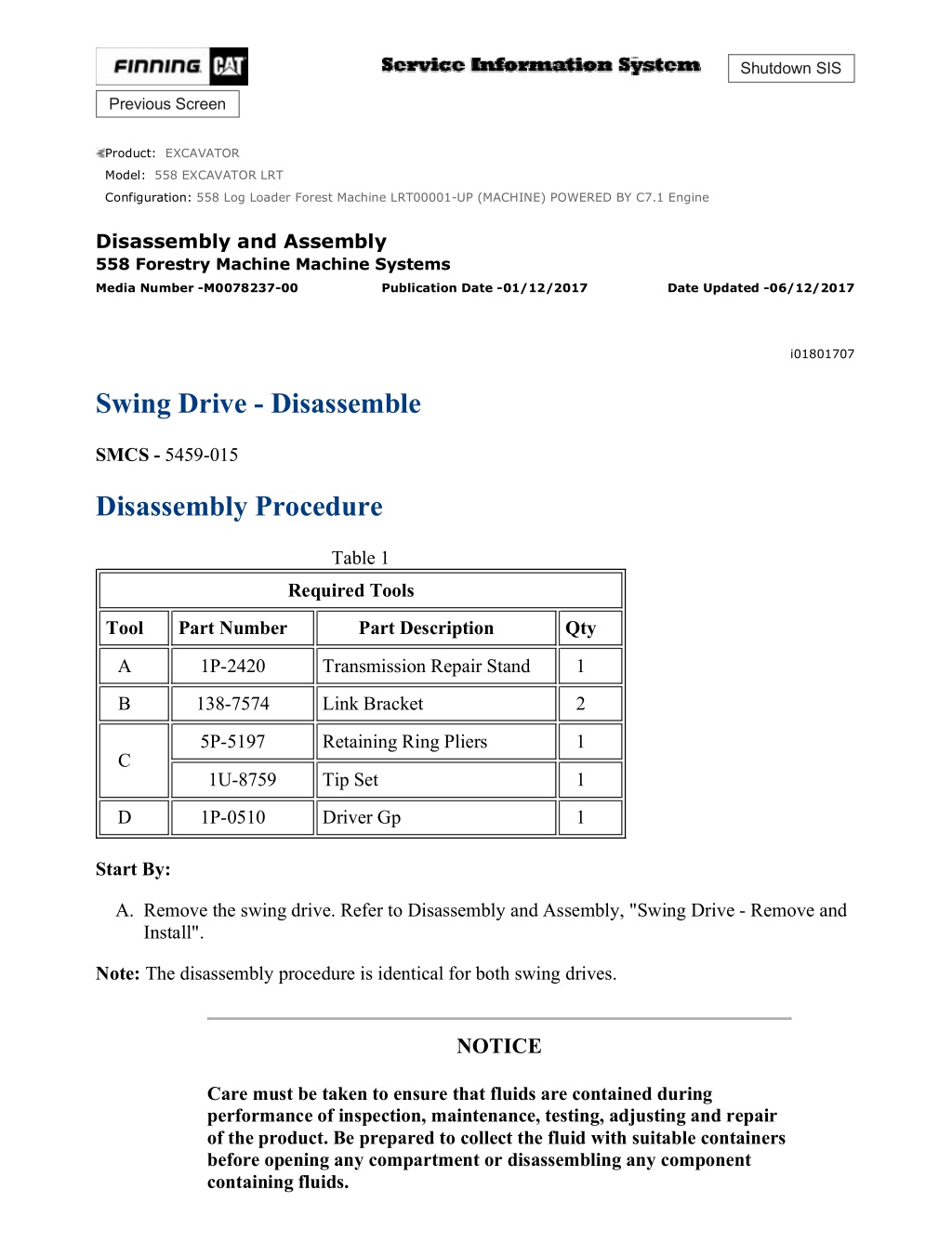
558 Log Loader Forest Machine LRT00001-UP (MACHINE) POWERED BY C7.1 E... 1/11 Shutdown SIS Previous Screen Product: EXCAVATOR Model: 558 EXCAVATOR LRT Configuration: 558 Log Loader Forest Machine LRT00001-UP (MACHINE) POWERED BY C7.1 Engine Disassembly and Assembly 558 Forestry Machine Machine Systems Media Number -M0078237-00 Publication Date -01/12/2017 Date Updated -06/12/2017 i01801707 Swing Drive - Disassemble SMCS - 5459-015 Disassembly Procedure Table 1 Required Tools Tool Part Number Part Description Qty A 1P-2420 Transmission Repair Stand 1 B 138-7574 Link Bracket 2 5P-5197 Retaining Ring Pliers 1 C 1U-8759 Tip Set 1 D 1P-0510 Driver Gp 1 Start By: A. Remove the swing drive. Refer to Disassembly and Assembly, "Swing Drive - Remove and Install". Note: The disassembly procedure is identical for both swing drives. NOTICE Care must be taken to ensure that fluids are contained during performance of inspection, maintenance, testing, adjusting and repair of the product. Be prepared to collect the fluid with suitable containers before opening any compartment or disassembling any component containing fluids. https://127.0.0.1/sisweb/sisweb/techdoc/techdoc_print_page.jsp?returnurl=/sisw... 2021/2/2
558 Log Loader Forest Machine LRT00001-UP (MACHINE) POWERED BY C7.1 E... 2/11 Refer to Special Publication, NENG2500, "Caterpillar Tools and Shop Products Guide" for tools and supplies suitable to collect and contain fluids on Caterpillar products. Dispose of all fluids according to local regulations and mandates. Illustration 1 g00869217 1. Use a suitable device and a hoist to place the swing drive on Tooling (A). The weight of the swing drive is approximately 510 kg (1125 lb). 2. Open the drain valve, and drain the oil from the swing drive into a suitable container for storage or disposal. The capacity of the swing drive is 19 L (5 US gal). If necessary, remove the drain valve from the swing drive housing. Illustration 2 g00869266 3. Remove bolts (1) from cover (2) . https://127.0.0.1/sisweb/sisweb/techdoc/techdoc_print_page.jsp?returnurl=/sisw... 2021/2/2
558 Log Loader Forest Machine LRT00001-UP (MACHINE) POWERED BY C7.1 E... 3/11 Illustration 3 g00869281 4. Remove sun gear (3) from carrier assembly (4) . Illustration 4 g00869294 5. Remove spacer (5) from carrier assembly (4) . 6. Use two people to remove carrier assembly (4) from the swing drive. The weight of the carrier assembly is approximately 36 kg (80 lb). 7. Disassemble carrier assembly (4) . https://127.0.0.1/sisweb/sisweb/techdoc/techdoc_print_page.jsp?returnurl=/sisw... 2021/2/2
https://www.ebooklibonline.com Hello dear friend! Thank you very much for reading. Enter the link into your browser. The full manual is available for immediate download. https://www.ebooklibonline.com
558 Log Loader Forest Machine LRT00001-UP (MACHINE) POWERED BY C7.1 E... 4/11 Illustration 5 g00869309 a. Use a hammer and a punch to drive spring pin (6) into planetary shaft (7) . Illustration 6 g00869315 b. Remove planetary shaft (7), thrust washer (8), thrust washer (11), and planetary gear (9) from the carrier. c. Remove bearing (10) from planetary gear (9) . d. Use a hammer and a punch in order to remove spring pin (6) from the planetary shaft (7) . e. Repeat Steps 7.a through 7.d in order to remove the other three planetary gears from the carrier assembly. Illustration 7 g00869377 8. Use a screwdriver in order to remove upper retaining ring (12) from sun gear (13) . 9. Remove sun gear (13) from carrier assembly (4) . https://127.0.0.1/sisweb/sisweb/techdoc/techdoc_print_page.jsp?returnurl=/sisw... 2021/2/2
558 Log Loader Forest Machine LRT00001-UP (MACHINE) POWERED BY C7.1 E... 5/11 Illustration 8 g00869383 10. Remove retaining ring (14) from the sun gear. Illustration 9 g00869390 11. Use Tooling (B) and a hoist to remove ring gear (15) from swing drive housing (16). The weight of the ring gear is approximately 80 kg (175 lb). Illustration 10 g00869406 https://127.0.0.1/sisweb/sisweb/techdoc/techdoc_print_page.jsp?returnurl=/sisw... 2021/2/2
558 Log Loader Forest Machine LRT00001-UP (MACHINE) POWERED BY C7.1 E... 6/11 12. Remove spacer (17) from carrier assembly (18) . Illustration 11 g00869460 13. Use two screwdrivers to remove retaining ring (19) . Illustration 12 g00869464 14. Use a hoist and a lifting sling to remove carrier assembly (20). The weight of the carrier assembly is approximately 68 kg (150 lb). 15. Disassemble carrier assembly (20) . https://127.0.0.1/sisweb/sisweb/techdoc/techdoc_print_page.jsp?returnurl=/sisw... 2021/2/2
558 Log Loader Forest Machine LRT00001-UP (MACHINE) POWERED BY C7.1 E... 7/11 Illustration 13 g00869477 a. Use a hammer and a punch to drive spring pin (21) into planetary shaft (22) . Illustration 14 g00869483 b. Remove planetary shaft (22), thrust washer (23), thrust washer (27), and planetary gear (25) from the carrier. c. Remove bearing (24) and (26) from planetary gear (25) . d. Use a hammer and a punch to remove spring pin (21) from planetary shaft (22) . e. Repeat Steps 15.a through 15.d in order to remove the other three planetary gears from the carrier assembly. https://127.0.0.1/sisweb/sisweb/techdoc/techdoc_print_page.jsp?returnurl=/sisw... 2021/2/2
558 Log Loader Forest Machine LRT00001-UP (MACHINE) POWERED BY C7.1 E... 8/11 Illustration 15 g00869500 16. Use Tooling (C) to remove retaining ring (28) . Illustration 16 g00869545 17. Place swing drive housing (16) sideways. Remove two bolts (30) from bearing cage (29) . Illustration 17 g00869554 https://127.0.0.1/sisweb/sisweb/techdoc/techdoc_print_page.jsp?returnurl=/sisw... 2021/2/2
558 Log Loader Forest Machine LRT00001-UP (MACHINE) POWERED BY C7.1 E... 9/11 18. Put swing drive housing (16) in a press. The combined weight of the swing drive housing, the pinion shaft, and the bearing cage is approximately 300 kg (660 lb). Illustration 18 g00869551 19. Place two Steel Supports (d) under the face of bearing cage (29) . 20. Place a wood block directly under the pinion shaft (31). This will prevent the pinion shaft from falling, while the shaft is pressed out of the swing drive housing. Note: Use care when components are pushed from the swing drive housing. Avoid injury to personnel. Also, avoid damage to components. 21. Push pinion shaft (31) from the swing drive housing. The weight of the pinion shaft is approximately 77 kg (170 lb). 22. Remove the swing drive housing and the pinion shaft from the press. The weight of the swing drive housing is approximately 222 kg (490 lb). The weight of the pinion shaft is approximately 77 kg (170 lb). Illustration 19 g00869569 23. Place swing drive housing (16) sideways. Remove the remaining six bolts (30) from the swing drive. Remove bearing cage (29) from the swing drive. https://127.0.0.1/sisweb/sisweb/techdoc/techdoc_print_page.jsp?returnurl=/sisw... 2021/2/2
558 Log Loader Forest Machine LRT00001-UP (MACHINE) POWERED BY C7.1 ... 10/11 Illustration 20 g00869899 24. Remove two lip type seals (32) and O-ring seal (33) from bearing cage (29) . Illustration 21 g00869650 Illustration 22 g00869654 https://127.0.0.1/sisweb/sisweb/techdoc/techdoc_print_page.jsp?returnurl=/sisw... 2021/2/2
558 Log Loader Forest Machine LRT00001-UP (MACHINE) POWERED BY C7.1 ... 11/11 Note: Use care when the components are pushed from the swing drive housing. Avoid injury to personnel. Also, avoid damage to components. 25. Place swing drive (16) in a press. Use Tooling (D) to push bearing (34), spacer (35), and bearing (36) from the swing drive. The weight of the swing drive is approximately 150 kg (330 lb). The weight of bearing (34) is approximately 11 kg (25 lb). The weight of spacer (35) is approximately 4 kg (8 lb). The weight of bearing (36) is approximately 35 kg (77 lb). Copyright 1993 - 2021 Caterpillar Inc. Tue Feb 2 22:35:20 UTC+0800 2021 All Rights Reserved. Private Network For SIS Licensees. https://127.0.0.1/sisweb/sisweb/techdoc/techdoc_print_page.jsp?returnurl=/sisw... 2021/2/2
558 Log Loader Forest Machine LRT00001-UP (MACHINE) POWERED BY C7.1 E... 1/13 Shutdown SIS Previous Screen Product: EXCAVATOR Model: 558 EXCAVATOR LRT Configuration: 558 Log Loader Forest Machine LRT00001-UP (MACHINE) POWERED BY C7.1 Engine Disassembly and Assembly 558 Forestry Machine Machine Systems Media Number -M0078237-00 Publication Date -01/12/2017 Date Updated -06/12/2017 i02406626 Swing Drive - Assemble SMCS - 5459-016 Assembly Procedure Table 1 Required Tools Tool Part Number Part Description Qty A 138-7574 Link Bracket 2 B 1P-2420 Transmission Repair Stand 1 5P-5197 Retaining ring pliers 1 C 1U-8759 Tip Set 1 D 1P-0510 Drive Group 1 E 1U-6396 O-Ring Assembly Compound 1 F 5P-3931 Anti-Seize Compound 1 G 5P-0960 Grease Cartridge 1 H 9S-3263 Thread Lock Compound 1 J 1U-8846 Gasket Sealant 1 Note: Cleanliness is an important factor. Before assembly, all parts should be thoroughly cleaned in cleaning fluid. Allow the parts to air dry. Wiping cloths or rags should not be used to dry parts. Lint may be deposited on the parts which may cause later trouble. Inspect all parts. If any parts are worn or damaged, use new parts for replacement. All disassembly and all assembly procedures must be performed on a clean work surface and in a clean hydraulic area. Keep cleaned parts covered and protected at all times. https://127.0.0.1/sisweb/sisweb/techdoc/techdoc_print_page.jsp?returnurl=/sisw... 2021/2/2
558 Log Loader Forest Machine LRT00001-UP (MACHINE) POWERED BY C7.1 E... 2/13 Note: O-rings, gaskets, and seals should always be replaced. A used O-ring may not have the same sealing properties as a new O-ring. Use Tooling (E) during the assembly procedure. NOTICE Care must be taken to ensure that fluids are contained during performance of inspection, maintenance, testing, adjusting, and repair of the product. Be prepared to collect the fluid with suitable containers before opening any compartment or disassembling any component containing fluids. Refer to Special Publication, NENG2500, "Dealer Service Tool Catalog" for tools and supplies suitable to collect and contain fluids on Cat products. Dispose of all fluids according to local regulations and mandates. 1. Make sure that all parts of the swing drive are thoroughly clean and free of dirt and debris prior to assembly. Illustration 1 g00725394 2. ApplyTooling (F) on the outside diameter of bearing (37) and the inside diameter of swing drive housing (19). 3. Lower the temperature of bearing (37). Install bearing (37) in the swing drive housing. It may be necessary to use a hammer and a punch to properly seat the bearing in the swing drive housing. https://127.0.0.1/sisweb/sisweb/techdoc/techdoc_print_page.jsp?returnurl=/sisw... 2021/2/2
558 Log Loader Forest Machine LRT00001-UP (MACHINE) POWERED BY C7.1 E... 3/13 Illustration 2 g00725388 4. Install O-ring seal (35) into bearing cage (31). 5. Install lip seals (34) in bearing cage (31). 6. ApplyTooling (G) on the lip of each seal. Illustration 3 g00725547 7. Carefully install cage (31) over pinion shaft (33). Illustration 4 g00725554 8. Raise the temperature of bearing (39) and install bearing (39) on pinion shaft (33). https://127.0.0.1/sisweb/sisweb/techdoc/techdoc_print_page.jsp?returnurl=/sisw... 2021/2/2
558 Log Loader Forest Machine LRT00001-UP (MACHINE) POWERED BY C7.1 E... 4/13 Illustration 5 g00725572 9. Install spacer (38) on top of bearing assembly (37), as shown. Note: Lip (e) for spacer (38) must face opposite bearing assembly (37), as shown. Illustration 6 g00725575 10. Put swing drive housing (19) in a suitable press. 11. Apply Tooling (F) on the outside diameter of bearing assembly (39) and the inside diameter of the swing drive housing. 12. Install pinion shaft (33), bearing cage (31), bearing assembly (39), through spacer (38) and bearing (37). Note: It may be necessary to reposition the press so that bearing assembly (39) is installed evenly into the swing drive housing. Note: Align bearing cage (31) with the swing drive housing during installation of the pinion shaft. Temporarily install bolts that will hold bearing cage (31) to the swing drive housing. https://127.0.0.1/sisweb/sisweb/techdoc/techdoc_print_page.jsp?returnurl=/sisw... 2021/2/2
558 Log Loader Forest Machine LRT00001-UP (MACHINE) POWERED BY C7.1 E... 5/13 Illustration 7 g00725595 13. Remove the swing drive from a suitable press and place the swing drive sideways. The combined weight of the swing drive housing, the pinion shaft, and the bearing cage is approximately 152 kg (335 lb). 14. Remove the temporary bolts that are holding the bearing cage in position. 15. ApplyTooling (H) on the threads of bolts (32) that hold bearing cage (31) to swing drive housing (19). 16. Tighten bolts (32) to a torque of 100 20 N m (75 15 lb ft). Illustration 8 g00725607 17. Raise the temperature of bearing inner race (36) and install bearing inner race (36) on the pinion shaft (33). Note: Make sure that the shaft is centered in the swing drive housing, before you install bearing inner race (36). https://127.0.0.1/sisweb/sisweb/techdoc/techdoc_print_page.jsp?returnurl=/sisw... 2021/2/2
558 Log Loader Forest Machine LRT00001-UP (MACHINE) POWERED BY C7.1 E... 6/13 Illustration 9 g00725270 18. Use Tooling (C) to install retaining ring (30). 19. Assemble the carrier assembly (21), as follows: Illustration 10 g00725260 a. Apply clean SAE 30W oil on bearing (26) and bearing (28). Install bearings (26) and (28) into planetary gear (27). b. Install thrust washer (25) on one side of planetary gear (27). c. Install thrust washer (29) on the other side of planetary gear (27). d. Use a deburring tool in order to remove the metal burr from the openings in the carrier. e. Install planetary gear (27) and the thrust washers in the carrier assembly (21). https://127.0.0.1/sisweb/sisweb/techdoc/techdoc_print_page.jsp?returnurl=/sisw... 2021/2/2
558 Log Loader Forest Machine LRT00001-UP (MACHINE) POWERED BY C7.1 E... 7/13 Illustration 11 g00725252 f. Install planetary shaft (24) through the gear assembly into the carrier assembly. Make sure that the spring pin hole in the planetary shaft is in alignment with the spring pin hole in the carrier. Illustration 12 g00703700 g. Drive spring pin (23) into planetary shaft (24). Orient the split in spring pin (23) vertically to the carrier. Align the split in the spring pin to the top or to the bottom. Make a stake mark on each side of the spring pin hole in the carrier. Each stake mark should be approximately 2.25 0.75 mm (0.090 0.030 inch) from the outside diameter of the spring pin hole. h. Repeat Steps 19.a through 19.g in order to install the other three planetary gears (27) in the carrier assembly. https://127.0.0.1/sisweb/sisweb/techdoc/techdoc_print_page.jsp?returnurl=/sisw... 2021/2/2
558 Log Loader Forest Machine LRT00001-UP (MACHINE) POWERED BY C7.1 E... 8/13 Illustration 13 g00725203 20. Use two persons and install carrier assembly (21) into the housing. The weight of carrier assembly (21) is approximately 40 kg (88 lb). Illustration 14 g00725194 21. Install retaining ring (22). Illustration 15 g00725186 22. Install spacer (20) into carrier assembly (21). https://127.0.0.1/sisweb/sisweb/techdoc/techdoc_print_page.jsp?returnurl=/sisw... 2021/2/2
558 Log Loader Forest Machine LRT00001-UP (MACHINE) POWERED BY C7.1 E... 9/13 Illustration 16 g00725166 23. Make sure that the mating surfaces of ring gear (18) and swing drive housing (19) are thoroughly clean. 24. Apply Tooling (J) to the face of swing drive housing (19) and the face of ring gear (18). 25. Install Tooling (A) onto ring gear (18). The weight of ring gear (18) is approximately 36 kg (80 lb). 26. Install ring gear (18) onto the swing drive housing (19). Illustration 17 g00725145 27. Install retaining ring (17) into the sun gear. https://127.0.0.1/sisweb/sisweb/techdoc/techdoc_print_page.jsp?returnurl=/sisw... 2021/2/2
558 Log Loader Forest Machine LRT00001-UP (MACHINE) POWERED BY C7.1 ... 10/13 Illustration 18 g00724866 28. Install carrier assembly (7) into the sun gear. Install retaining ring (15) into sun gear (16). 29. Assemble carrier assembly (7), as follows: Illustration 19 g00724862 a. Apply clean SAE 30W oil on bearing (13). Install bearing (13) in planetary gear (12). b. Install a thrust washer (11) on one side of planetary gear (12). c. Install a thrust washer (14) on the other side of planetary gear (12). d. Use a deburring tool in order to remove the metal burr from the openings in the carrier. e. Install planetary gear (12) and the thrust washers in the carrier assembly (7). Illustration 20 g00724860 f. Install planetary shaft (10) through the gear assembly into the carrier assembly. Make sure that the spring pin hole in the planetary shaft is in alignment with the spring pin hole in the carrier. https://127.0.0.1/sisweb/sisweb/techdoc/techdoc_print_page.jsp?returnurl=/sisw... 2021/2/2
558 Log Loader Forest Machine LRT00001-UP (MACHINE) POWERED BY C7.1 ... 11/13 Illustration 21 g00703700 g. Drive spring pin (9) into planetary shaft (10). Orient the split in spring pin (9) vertically to the carrier. Align the split in the spring pin to the top or to the bottom. Make a stake mark on each side of the spring pin hole in the carrier. Each stake mark should be approximately 2.25 0.75 mm (0.09 0.03 inch) from the outside diameter of the spring pin hole. h. Repeat Steps 29.a through 29.g for the remaining gear assemblies. Illustration 22 g00724856 30. Install carrier assembly (7) in the ring gear. 31. Install spacer (8) into carrier assembly (7). https://127.0.0.1/sisweb/sisweb/techdoc/techdoc_print_page.jsp?returnurl=/sisw... 2021/2/2
558 Log Loader Forest Machine LRT00001-UP (MACHINE) POWERED BY C7.1 ... 12/13 Illustration 23 g00724854 32. Install sun gear (6) into carrier assembly (7). Illustration 24 g00724840 33. Make sure that the mating surfaces of the ring gear and cover (5) are thoroughly clean. 34. Apply on the flange surface of the ring gear and cover (5). 35. Fasten Tooling (A) and a suitable lifting device to cover (5). Put the cover in the original position on the ring gear. Make sure that the cover is seated properly. Illustration 25 g00724843 https://127.0.0.1/sisweb/sisweb/techdoc/techdoc_print_page.jsp?returnurl=/sisw... 2021/2/2
558 Log Loader Forest Machine LRT00001-UP (MACHINE) POWERED BY C7.1 ... 13/13 36. ApplyTooling (H) on the threads of bolts (4). 37. Install the washers and bolts (4) that hold the cover, the ring gear, and the swing drive housing together. Tighten bolts (4) to a torque of 270 40 N m (200 30 lb ft). 38. Install fitting (3) into cover (5). Illustration 26 g00724832 39. Install oil level gauge (Dipstick) (1), filler breather cap assembly, and hose assembly (2) to the swing drive. 40. If the drain valve was removed from the swing drive housing, reinstall the drain valve. End By: a. Install the swing drive. Refer to Disassembly and Assembly, "Swing Drive - Install". Copyright 1993 - 2021 Caterpillar Inc. Tue Feb 2 22:36:16 UTC+0800 2021 All Rights Reserved. Private Network For SIS Licensees. https://127.0.0.1/sisweb/sisweb/techdoc/techdoc_print_page.jsp?returnurl=/sisw... 2021/2/2
558 Log Loader Forest Machine LRT00001-UP (MACHINE) POWERED BY C7.1 E... 1/7 Shutdown SIS Previous Screen Product: EXCAVATOR Model: 558 EXCAVATOR LRT Configuration: 558 Log Loader Forest Machine LRT00001-UP (MACHINE) POWERED BY C7.1 Engine Disassembly and Assembly 558 Forestry Machine Machine Systems Media Number -M0078237-00 Publication Date -01/12/2017 Date Updated -06/12/2017 i07034505 Swing Gear and Bearing - Remove and Install SMCS - 7063-010 Removal Procedure Table 1 Required Tools Part Number Tool Part Description Qty A 138-7576 Link Brackets 4 Hydraulic Pump and Motor Gp (115 V 50/60 Hz Single Phase) (1) 132-8223 1 B 1U-6221 Hydraulic Torque Wrench Gp 1 132-8143 Wrench Link (36-MM LOW CLEARANCE HEX) 1 C - Loctite 380 Black Max - D 1P-0808 Multipurpose Grease - E - Loctite 17430 - F 5P-3931 Anti-Seize Compound - (1)132-8231 Hydraulic Pump and Motor Gp (220 V 50/60 Hz Single Phase) is also available. Start By: a. Remove the undercarriage frame. 1. Remove all the grease from the swing gear and bearing. Put the grease in a suitable container for storage or disposal. https://127.0.0.1/sisweb/sisweb/techdoc/techdoc_print_page.jsp?returnurl=/sisw... 2021/2/2
558 Log Loader Forest Machine LRT00001-UP (MACHINE) POWERED BY C7.1 E... 2/7 Illustration 1 g00520664 2. Put an alignment mark on swing gear and bearing (1) and on the undercarriage frame assembly for assembly purposes. Attach Tooling (A) and a suitable lifting device to swing gear and bearing (1), as shown. Apply slight lifting tension to swing gear and bearing (1). Illustration 2 g00520670 3. Use Tooling (B) to remove bolts (2) and the spacers that hold swing gear and bearing (1) to the undercarriage frame. 4. Remove swing gear and bearing (1). The weight of swing gear and bearing (1) is approximately 640 kg (1410 lb). https://127.0.0.1/sisweb/sisweb/techdoc/techdoc_print_page.jsp?returnurl=/sisw... 2021/2/2
558 Log Loader Forest Machine LRT00001-UP (MACHINE) POWERED BY C7.1 E... 3/7 Illustration 3 g02128394 Note: Inner dust seal (3) and outer dust seal (4) may have been installed dry and bonded to the swing gear and bearing. 5. Remove inner dust seal (3) and outer dust seal (4) from the swing gear and bearing. 6. Clean the seal grooves of the inner dust seal and the outer dust seal with a fine grit sandpaper. Use a cleaning solvent to clean the sealing grooves. Make sure that the seal grooves are thoroughly clean and dry prior to installing the new dust seals. Installation Procedure 1. Install swing gear and bearing (1) in the reverse order of removal. https://127.0.0.1/sisweb/sisweb/techdoc/techdoc_print_page.jsp?returnurl=/sisw... 2021/2/2
558 Log Loader Forest Machine LRT00001-UP (MACHINE) POWERED BY C7.1 E... 4/7 Illustration 4 g02128394 a. Use the following procedure to install the new inner dust seal (3) and the new outer dust seal (4): a. Use a wire brush to clean the grooves for the dust seal of the swing gear and bearing. Make sure that all the dirt and foreign material has been removed. b. Wash the grooves for the dust seal in a suitable solvent that will not leave an oily residue. c. The grooves for the dust seal in the swing gear and bearing must be clean and dry prior to installation of the dust seal. d. Cut one end of inner dust seal (3) at a 90 degree angle. Use a blunt tool to install the inner dust seal in the seal groove of the swing gear and bearing. e. Install the seal so that the lip of the seal is facing in the direction that is shown. https://127.0.0.1/sisweb/sisweb/techdoc/techdoc_print_page.jsp?returnurl=/sisw... 2021/2/2
Suggest: If the above button click is invalid. Please download this document first, and then click the above link to download the complete manual. Thank you so much for reading
558 Log Loader Forest Machine LRT00001-UP (MACHINE) POWERED BY C7.1 E... 5/7 f. Measure and cut the end of the inner dust seal at a 90 degree angle. Install the remaining end of the inner dust seal in the seal groove. g. Make sure that the inner dust seal is seated properly in the seal groove, all the way around the swing gear and bearing. Also, make sure that there is no gap between the ends of the inner dust seal. h. Pull each end of the inner dust seal out of the seal groove of the swing gear and bearing approximately 50.8 mm (2.00 inch). Apply Tooling (C) to each end of the inner dust seal to bond the seals together. i. Immediately reinstall the inner dust seal in the seal groove of the swing gear and bearing. Again, make sure that the entire inner dust seal is properly seated in the seal groove of the swing gear and bearing. No gap should exist between the ends of the inner dust seal. j. Ensure that the lip of inner dust seal has not adhered to the top of the bearing. k. Follow the procedure in Steps 1.a through 1.j to install outer dust seal (4) in the swing gear and bearing. Refer to Illustration 4 for proper seal orientation in the swing gear and bearing. l. Lubricate the swing gear and bearing with grease. Illustration 5 g00520664 https://127.0.0.1/sisweb/sisweb/techdoc/techdoc_print_page.jsp?returnurl=/sisw... 2021/2/2
https://www.ebooklibonline.com Hello dear friend! Thank you very much for reading. Enter the link into your browser. The full manual is available for immediate download. https://www.ebooklibonline.com

